Group Assignment
Characterize your lasercutter's focus, power, speed, rate, kerf, joint clearance and types.
Individual Assignment
Cut something on the vinylcutter design, lasercut, and document a parametric construction kit accounting for the lasercutter kerf, which can be assembled in multiple ways.
Group Assignment:
Here you can find our group assignment LINK
Laser Cutting
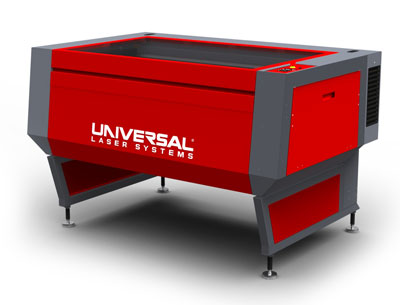
The laser machine we have in the lab is a CO2 laser cutter Universal Laser Systems ILS9.150D with power of 75 watts.
Cutting area: 900 x 600 mm
Materials: acrylics, cardboard, soft wood (ex balsa), hard wood for engraving, textile, fabric, foams and many others.
Supported file types: .dwg, .dxf (AutoCAD), .ai (Adobe Illustrator) and jpg for raster images.
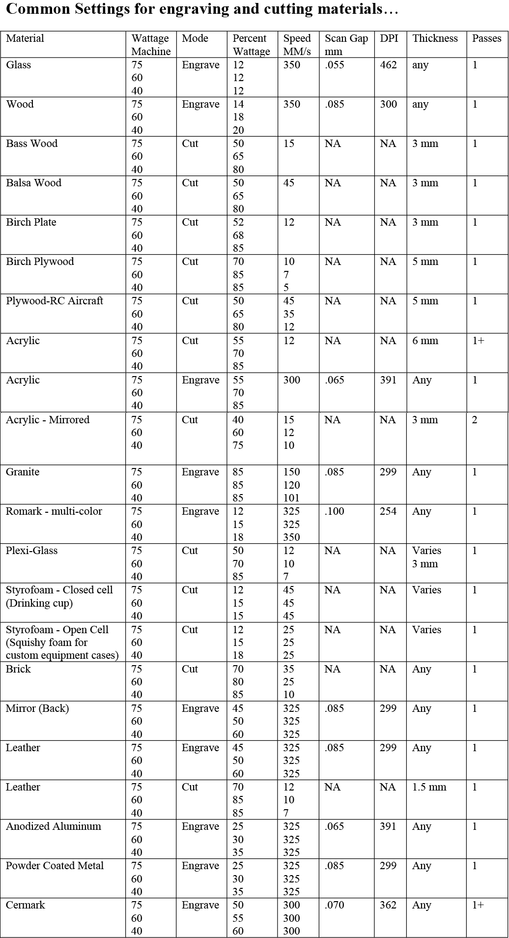
Suggested settings for the Power, Speed and PPI
KERF TEST
Laser machines while cutting through the material burn a small portion this is known as the laser kerf and it ranges depending on the material type.
Test I
Test I is a trial for the best settings speed and power for a specific material in my case it is 4 mm MDF. Using material as MDF we have to try reaching the best speed and power to have the smallest kerf.
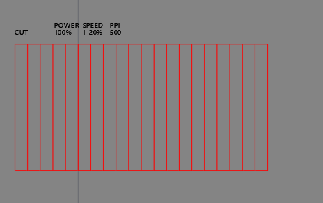
In this test I did several options for engraving (raster) and cutting (vector) in each I changed the speed, power and PPI.
For cutting the power remained 100% and the speed varied starting from 1% up to 20%.
According to the above test the best settings are power 100% and speed 8%
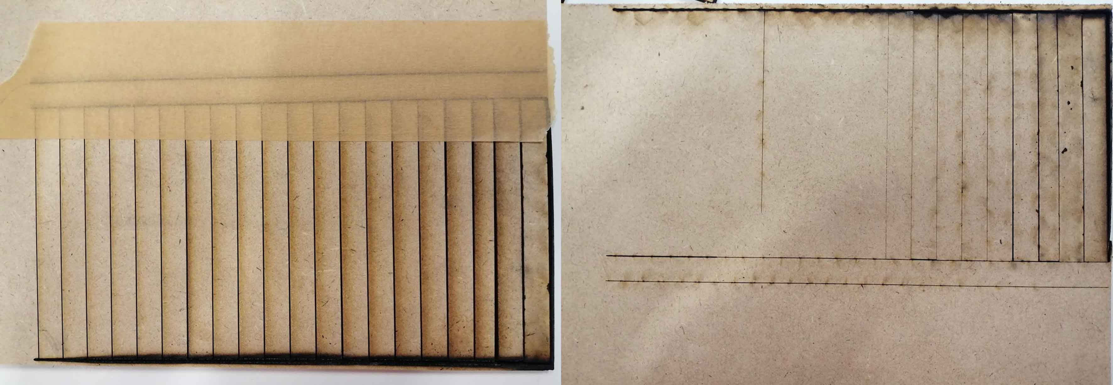
The objective of this test is to find the best settings for a specific material in my case mdf 4 mm. Power, speed and PPI are the settings. The speed was determined in order to have the smallest possible kerf.
The test is done by cutting several lines while changing the speed. The first line to be fully cut is the one with the lowest kerf.
The drawing was done on AutoCAD and the material used is MDF 4 mm.
Test II
The objective of test II is to measure the kerf using the best settings obtained from Test I.
In this test it is divided into two parts:
Part I: Cut several lines measure the outer frame and the length of the lines then divide the difference by the number of cuts.
A-B/number of cuts
Part II: Has the same objective as test I but in a different layout.
Preparing the file:
Draw everything in AutoCAD or Adobe Illustrator.
Use only the standard “index" colors: red, black, green, yellow, blue magenta and cyan.
In Adobe Illustrator the file should be RGB not CMYK and line stroke of 0.01 for cutting.
Using AutoCAD prepare a layout with different layers.
Draw the lines then for smoother cuts, all continuous line segments should be joined using the PEDIT/JOIN command in AutoCAD.
In the "Layer Properties Manager" assign the lineweights 0.00 and linetypes continuous for cutting.
Use the command overkill to make sure there are no duplicate lines to avoid and material burning.
Then plot the file choosing the right plotter name.
The next step will be in the laser machine user interface in which we can assign the different colors used with the power, speed, PPI and Z axis according to the materials to be used.
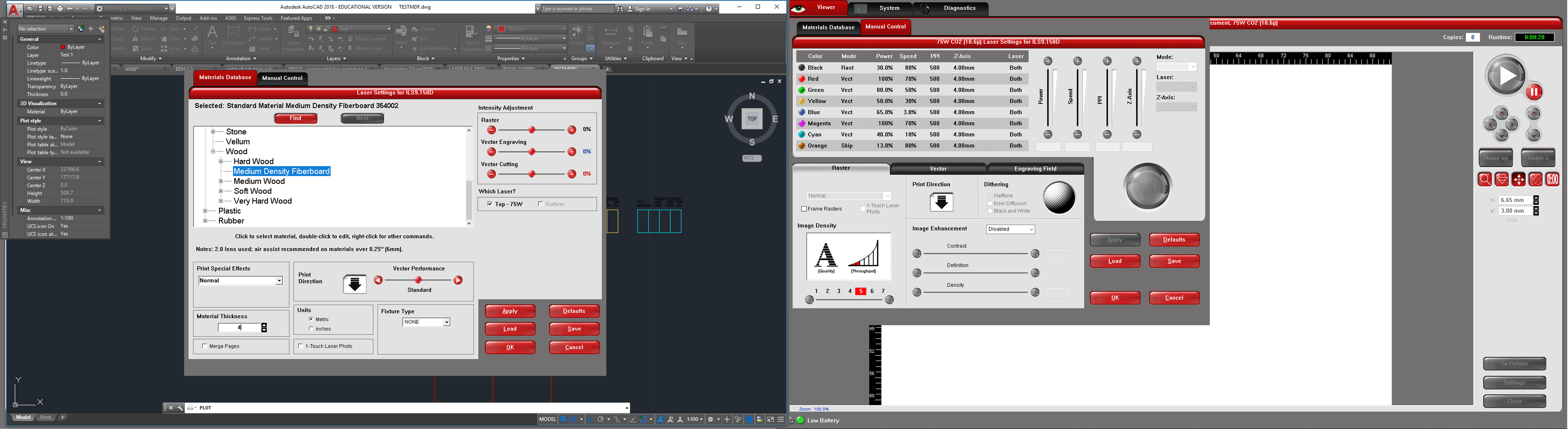
In the laser interface section material database we have to choose the material and material thickness so that the machine bed can change the z automatically and in the manual control we have to assign each color vector or raster with the p/s/ppi settings.
Then on the right corner we have the move setting in which we can locate the cutting postion of the file inside the machine.
The color mapping helps us assign different settings to each line in this way the machine understands that it shoud not cut all lines in the same settings.
Operating the machine
Before clicking on the play button on the screen we have to make sure of two things:
The compressor is turned on
The fan extractor is also turned on to take away the fumes and smoke preventing any toxic smells and fires.
Always make sure that the laser is not operating without any supervision.
Test Results
Using the settings of Test I speed 8% power 100% seemed to be the best.
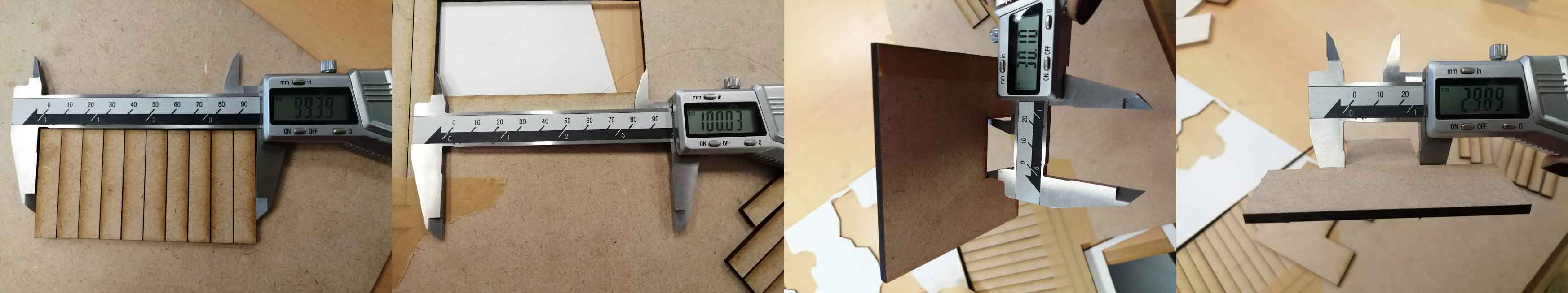
Test II part I: (100.03-99.39)/11=0.05
Test II part II: (30.10-29.89)/2=0.10
Engraving Test
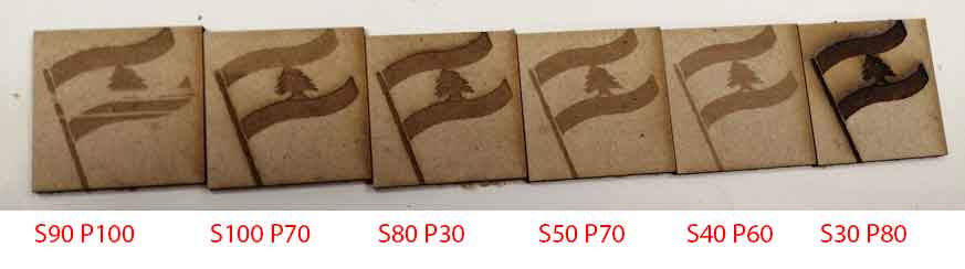
After checking several options of between speed and power the best results are S50 P70 and S40 P60.
As we increase the power and decrease the speed the laser machine burns the material more.
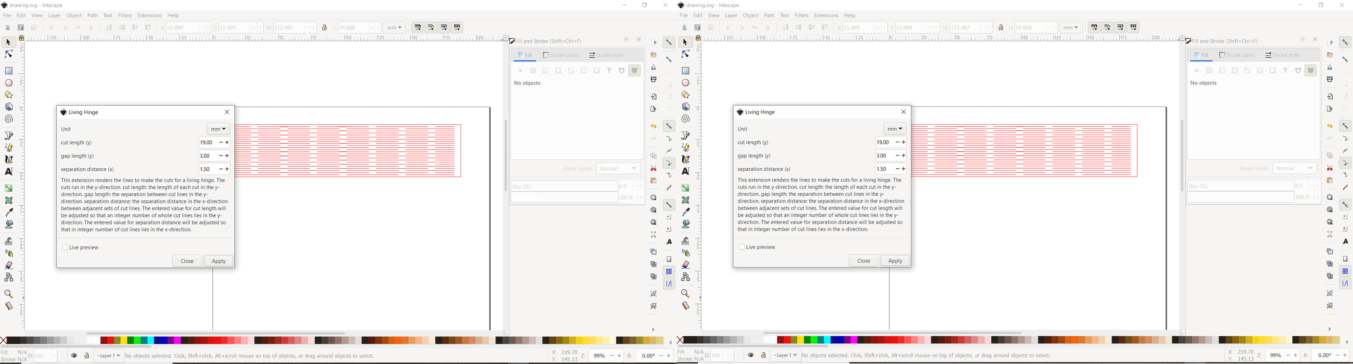
Inkscape
Using Inkscape software and the extension Living Hinge I drew a file to cut and experiment on the laser machine.
I made a rectangle and launched the extension: extensions - render - living hinge.
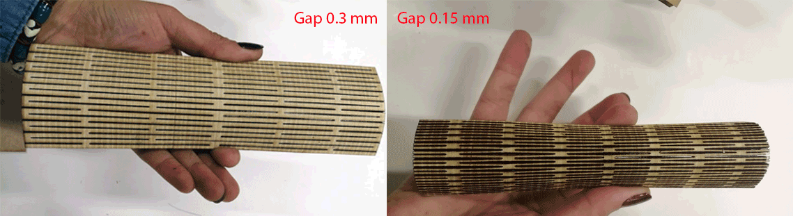
I tried two different options gap 3 mm and 1.5 mm using MDF 3 mm
Individual Assignment:
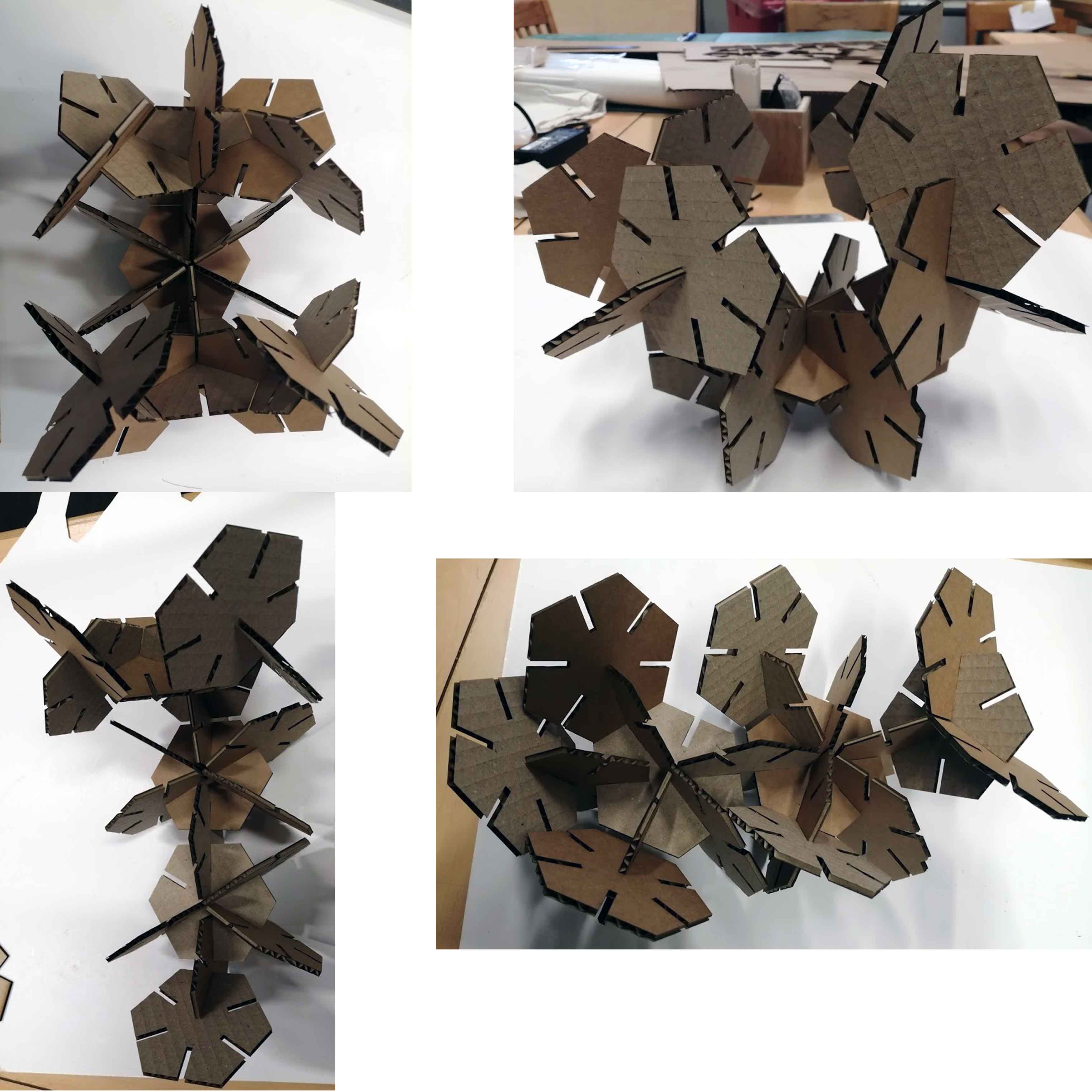
CONSTRUCTION KIT
My construction kit is made out of two different pieces cut several times on corrugated cardboard.
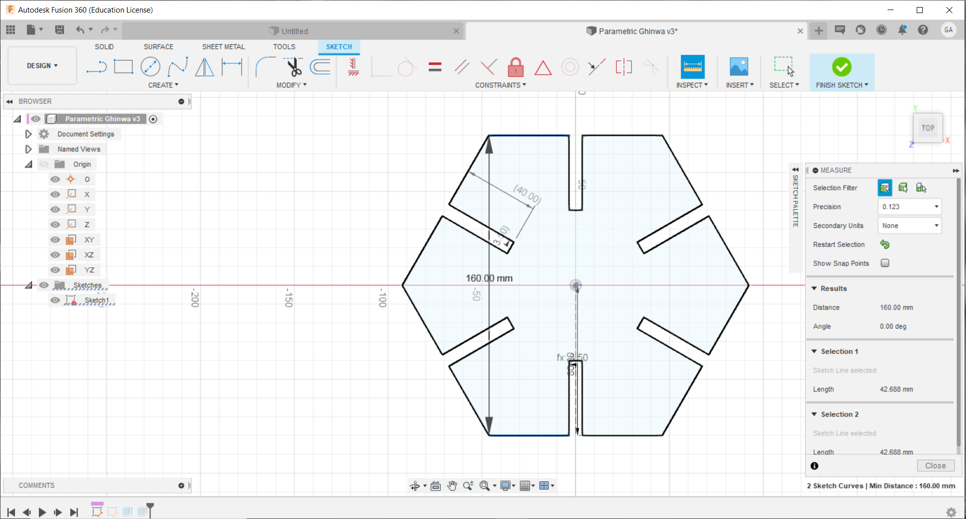
I designed the parts using Fusion 360
Part 1
Part 2
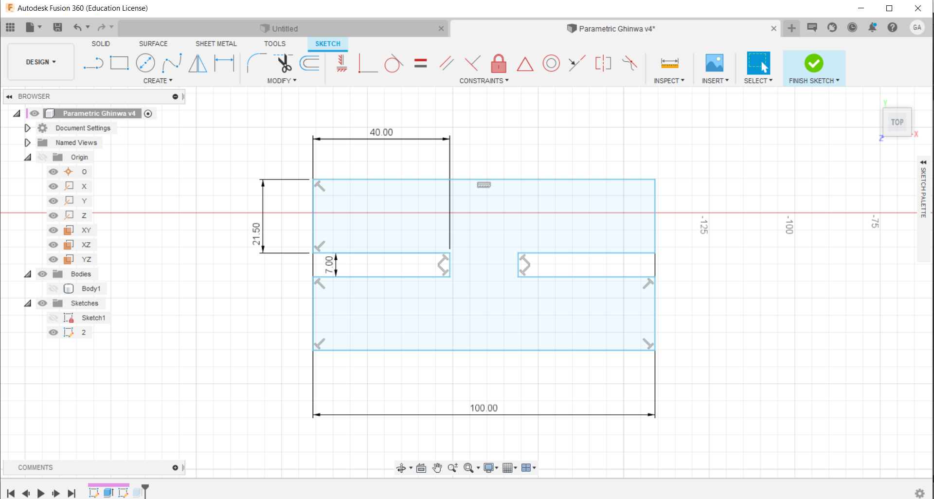
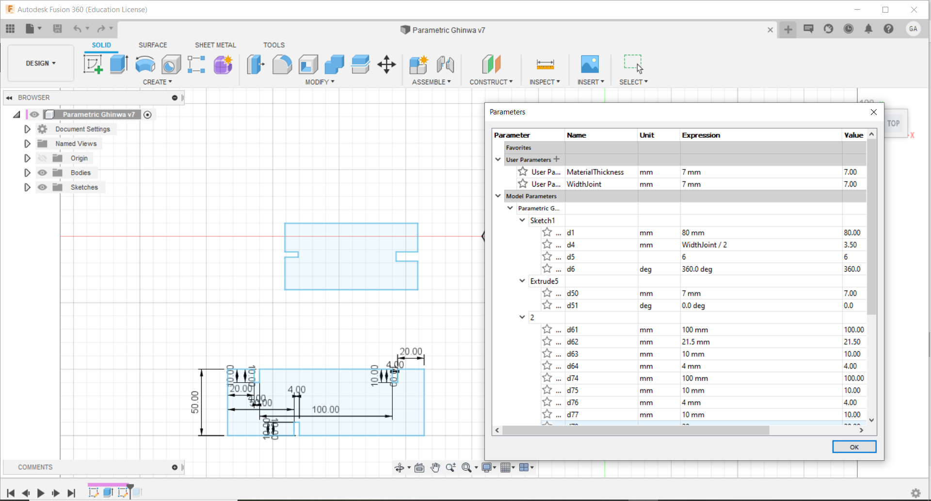
The kit should be designed in a parametric way. The first step is to draw a sketch and turn it into parameters and variables.
When we set a parameter or a numerical factor it defines a whole system.
These parameters depend on the material thickness, size of the parts, size of the slots ...
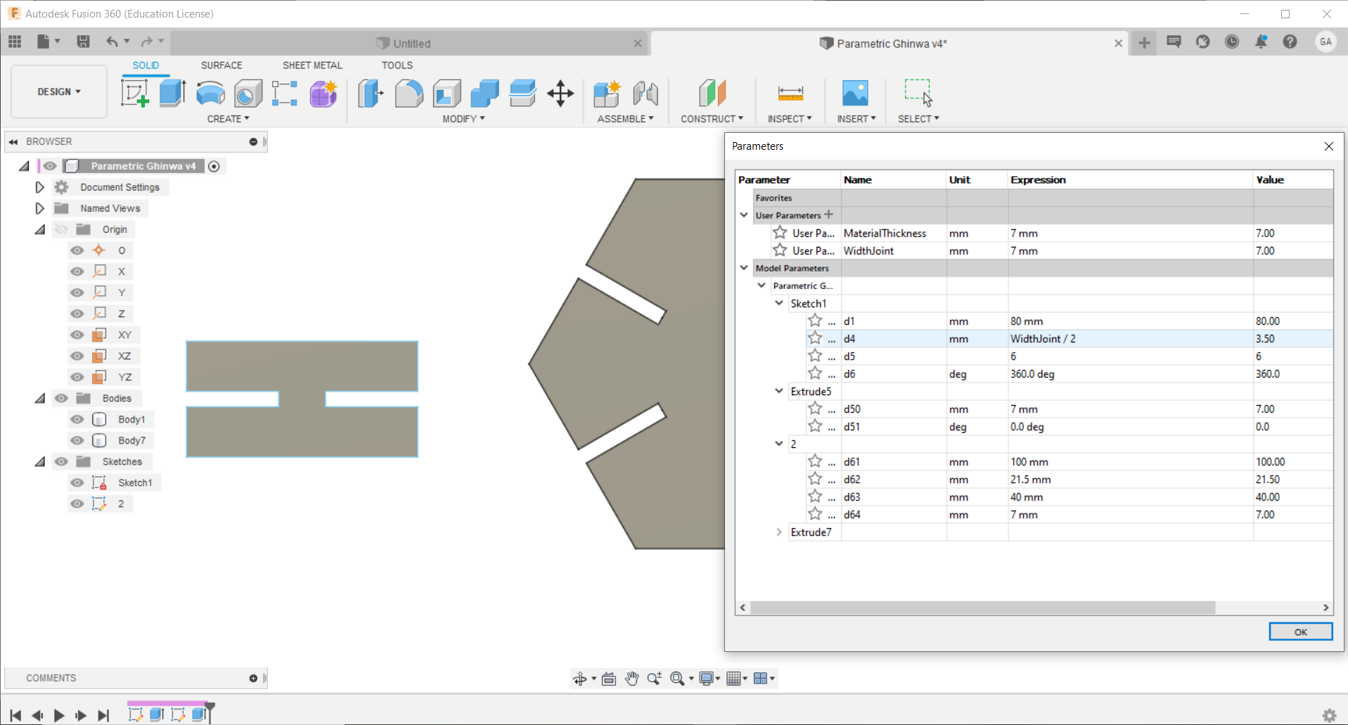
The parameters are:
Material Thickness
Joint Width
Joint Rotation Angle (360)
Number of Joints
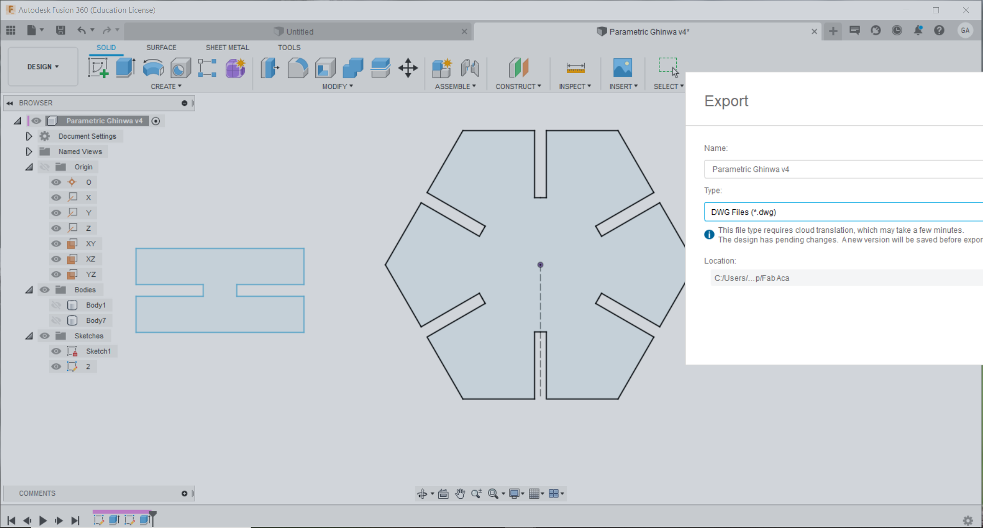
After defining these parameters and finalizing the file in FUSION 360 I exported the file as .dwg so I can open it in AutoCAD and laser cut the parts for assembly.
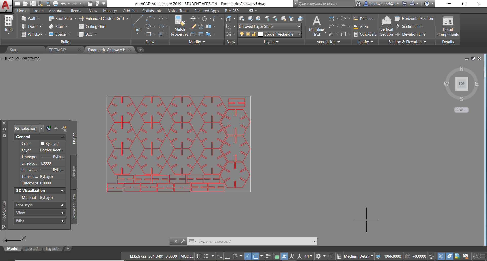
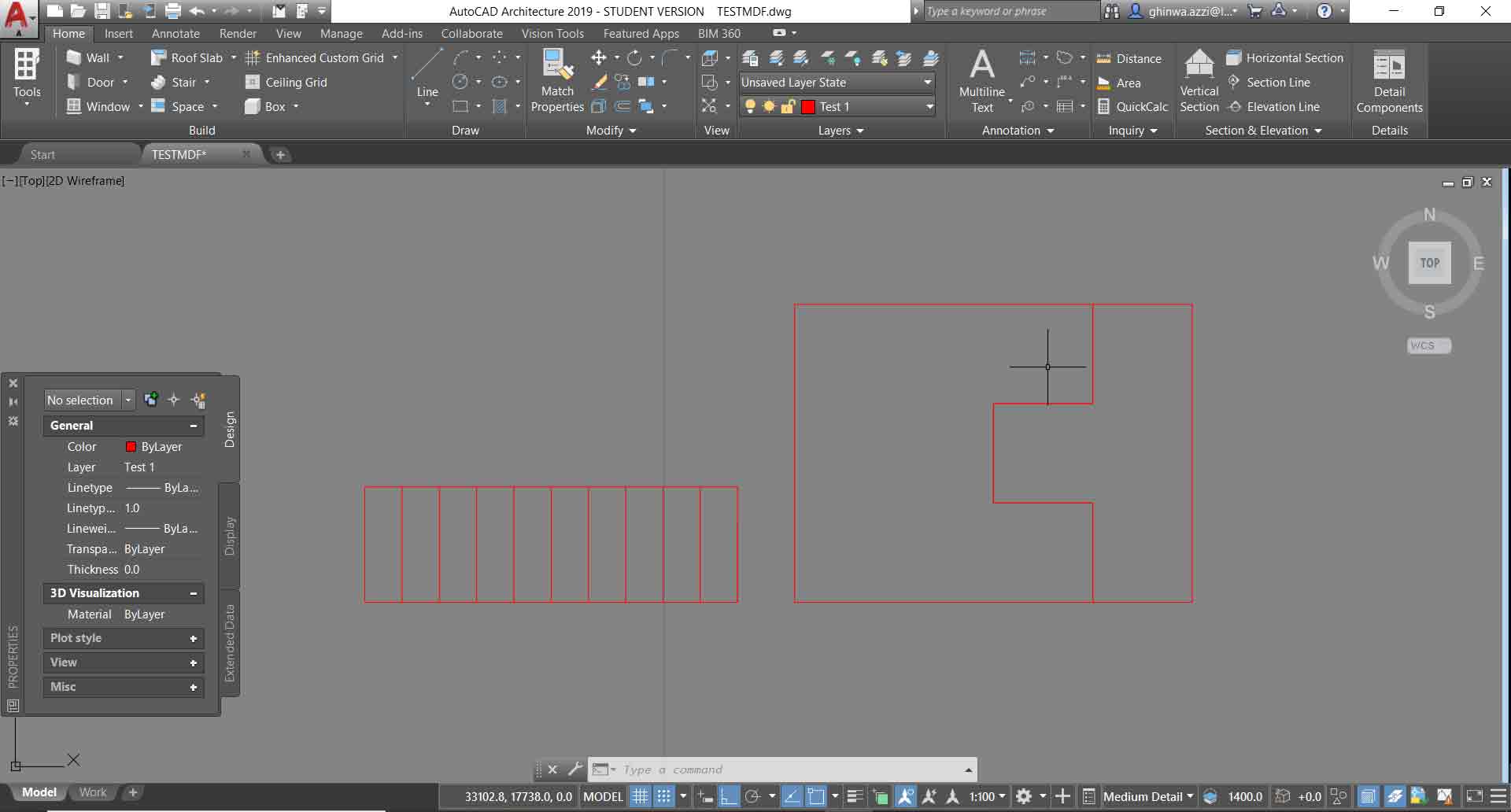
In AutoCAD I prepared the file to be cut using the laser machine.
First I fixed the layers red color is for cutting and the white rectangle is the material dimensions as the cutting are of the machine we have 900 x 600 mm.
Vinyl Cutter
Softwares Adobe Illustrator - Summa Winplot Cutter
The vinyl cutter that we have in the lab is Summa S class 2.
Maximum cutting area width: 1200mm
Supported file types: .ai (Adobe Illustrator) and .cdr (CorelDraw)

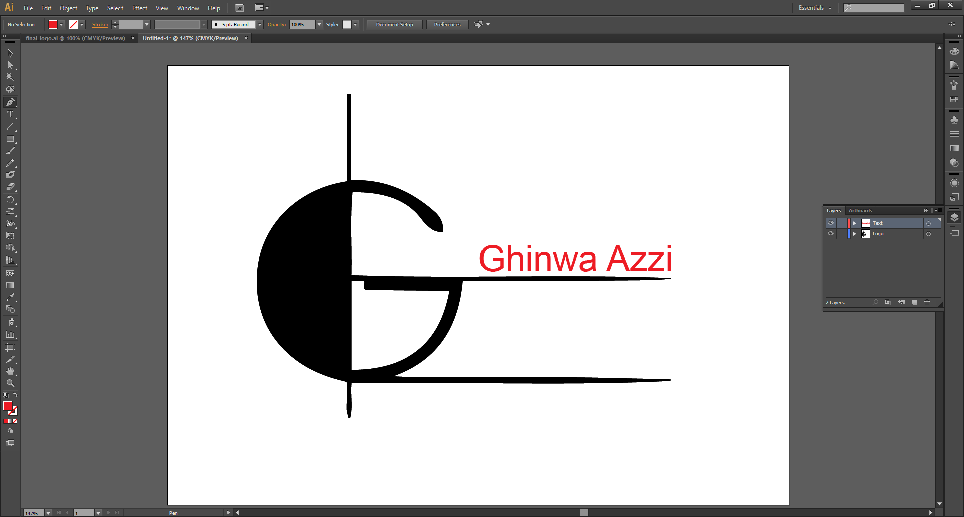
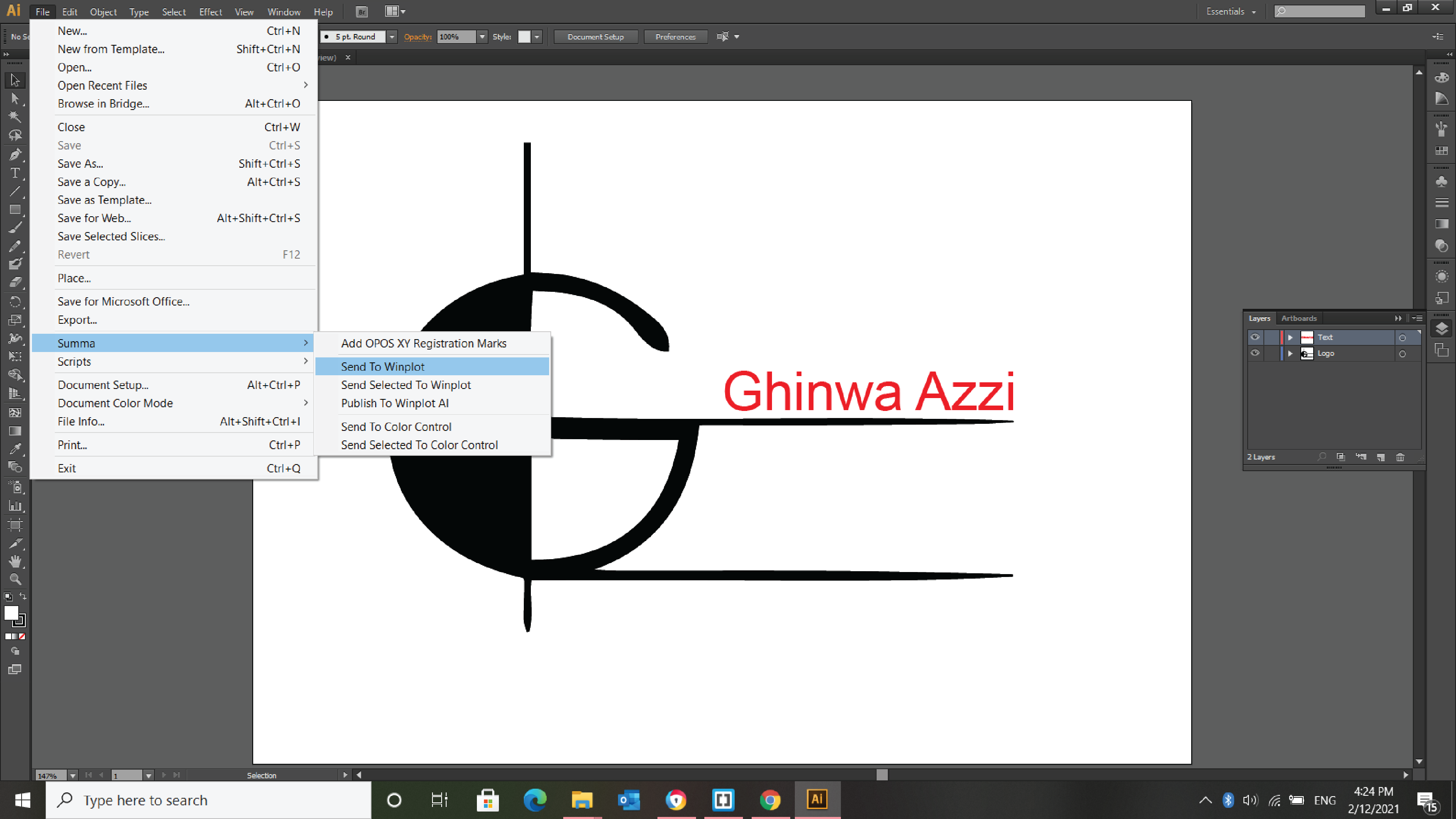
After designing the logo the vinyl cutter software is linked to adobe illutrator.
Go to file - Summa - Send To winplot.
I used adobe illustrator to design and adjust the logo.
After several trials I chose the font size and dimensions then aligned them all together.
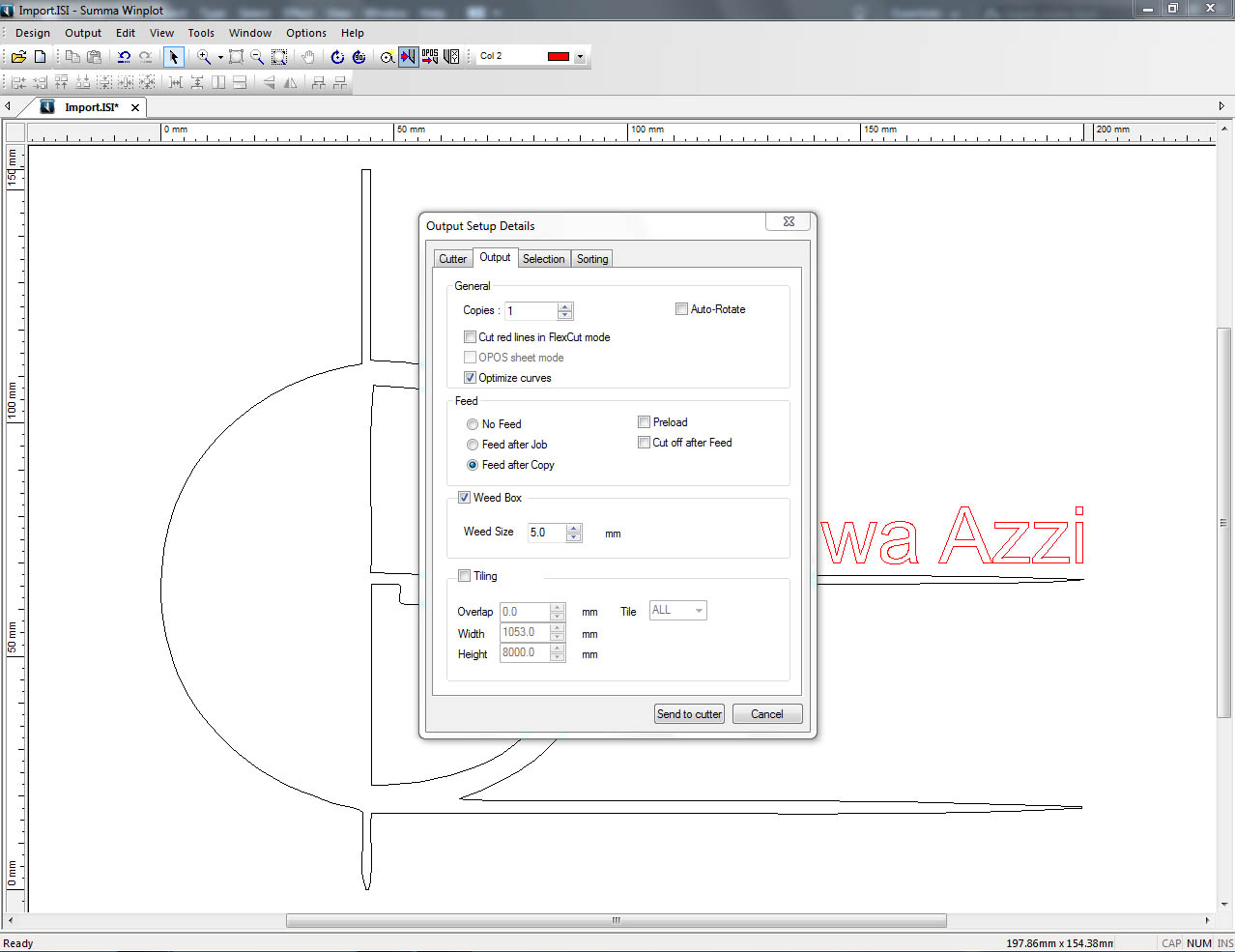
Once we send the file to the winplot software here we have several settings to check before cutting.
In the output setup details window we can choose the number of copies needed and if we want to have a border to be cut around the file weed box and its size.
Now we have to check the vinyl roll if it is loaded in the right place and if it is aligned with the machine so that while cutting we do not face jams with the tangential blade.
Final step is to click send to cutter on the pc.
So as you can see in this week I used several softwares: AutoCAD, Fusion 360, Inkscape and Adobe Illustrator.
I decided in the 3D Scanning and Printing Week to explore and try to design using another kind of parametric software which is Grasshopper. I designed the planting pots and the design cannot be easily made using subtractive processes like the ones used above in this assignment.

This work is licensed under a Creative Commons Attribution-NonCommercial-ShareAlike 4.0 International License