Group Assignment
Test the design rules for your 3D printer(s).
Individual Assignment
Design and 3D print an object (small, few cm3, limited by printer time), that could not be made subtractively.
3D scan an object (and optionally print it).
Here you can find our group assignment LINK
What is 3D printing?
Additive Manufacturing, also known as 3D Printing, refers to a range of layer-upon-layer manufacturing technologies, used to build a three-dimensional object both for prototyping and manufacturing purposes.
The process involves the successive forming of material layers under computer control, allowing complex components to be manufactured.
Types of 3D printers
Different types of 3D printers are ranged depending on the output quality and level of details wanted.
There are different 3D printing techniques like FDM (Fused-Deposition Modeling), SLA (Stereolithography) or SLS (Selective Laser Sintering) with their own unique features that can be used for prototyping.
Production Process
Step 1: Design your object or download open-source designs
Computer Aided Design: Autodesk Fusion 360, Solidworks, Rhino and Catia are some of the 3D modeling software that can be used to design parts for 3D printing.
GrabCAD, cults3D, all3Dp, and thingiverse are some of open source sites to download 3D models.
Step 2: Prepare the production files
Input Format: The input file that we want to send to the 3D printer should be saved in (.STL) format.
Step 3: Preparing the job
Slicing: a slicing software such as Cura or Preform is needed to prepare the machining job. In this software, you choose the best setting that you need based on the quality of the object you want to produce. The slicer will then generate the g.code, digital commands that will guide the machine during the production process.
Step 4: Send your file
In this step, the g.code is uploaded to the machine.
Step 5: Removing and Post Processing
Remove the printed object from the 3d printer and do some cleaning to the parts if needed.
How 3D Printers Work
FDM 3D Printing
Fused deposition modeling (FDM) is a 3D printing process that uses a continuous filament of a thermoplastic material.
Filament is fed from a large spool through a moving, heated printer extruder head, and is deposited on the growing work.
The print head is moved under computer control to define the printed shape. Usually the head moves in two dimensions to deposit one horizontal plane, or layer, at a time.
The work or the print head is then moved vertically by a small amount to begin a new layer.
There is a variety of 3D printing filaments to choose from. PLA and ABS filaments are mostly used in FDM 3D printing. What affects the choice of material is the application of the print since each material has its own properties.
Some definitions in FDM 3D printing
Infill:
Infill density is the amount of material printed inside the object, it is chosen depending on the strength needed, weight, and application of the print. Infill also affects the timing of the print, for instance, if we choose 100% infill we will have a full solid, and if we choose 0% infill our object will be hollow from the inside. Infills can also be in different patterns, they can as well affect the timing.
Wall thickness: to choose how thin or thick we want our walls to be. It can also affect the timing, quality, and level of detail of the print.
Layer height: it affects the final print than quality. If chosen properly, this setting will increase your print’s speed, resolution, and smoothness.
Supports: Supports are not a part of the printed object, but they are crucial for 3D printing, without supports we might have parts of the print hanging and falling down. The printer builds the supports in thin layers to be removed easily when after finishing.
Build plate adhesion: Skirt, brim, or raft, are options for build plate adhesion. They are needed to keep the first layers of the print from wrapping and lifting off the 3D printer bed.
SLA 3D Printing
Stereolithography (SLA) is another 3D printing process where an object is created by selectively curing a polymer resin layer-by-layer using an ultraviolet (UV) laser beam.
SLA 3D printers use a variety of specialized engineering materials and produce smooth, isotropic parts that are strong and highly detailed.
A model is created one layer at a time as a laser beam moves across a bath of liquid resin.
The laser's movements are guided by a 3D CAD program. SLA enables a model to be made with high resolution because each layer can be very thin. This means that handwork to finish the part is less than with other rapid prototyping technologies.
The variety of materials for SLA 3D printing depends on the application of the Print. Some of these materials are Rigid, flexible, clear, high temperature, dental and castable wax resin.
Applications
3D printers are ideal to create complex models, turning a computer file into a physical prototype.
FDM 3D printing can be used to make Artistic Shapes or Functional Parts for Working Prototypes and projects, usually in plastic material. Project can be gears, robotics arms, joystick parts and anything else. It can also print artistic stuff like vases, toys, accessories, jewelry, fashion, etc.
SLA 3D printing can be used to make prototypes with high precession, artistic prints, jewelry and fashion, and many medical applications.
It can be also used in the medical field to prototype new medical products.
Group Assignment
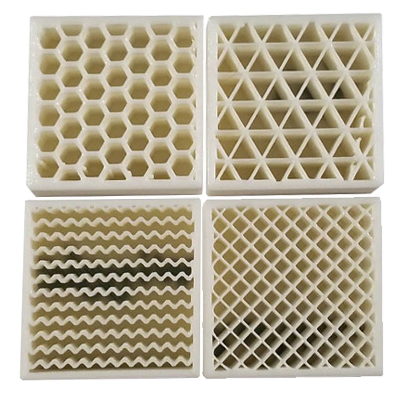
Our assignment for this week was to test the design rules of our 3D printers, to do so, we downloaded two open source 3D models that include multiple complex shapes to check possible problematic printing/slicing stuff that can be faced.
We used two individual Ultimaker 3D printers to test.
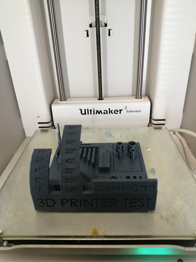
Test I
This 3D printer testing model was downloaded from the thingiverse. This test was performed on an Ultimaker 3D printer, and Cura was used as a slicing software to prepare the file.
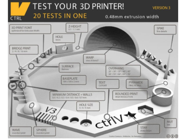
Settings:
Based on the recommendation of the designer
Layer height: 0.1 mm
Wall thickness: 1 mm
Infill: 30%
Without supports
With raft
Results:
M4 nut fits perfectly
Font is not distorted
Hole sizes: 4.9, 3.9, 2.9
Hole sizes: 4.9, 3.9, 2.9
Star with sharp edges
Minimal Distance that can be printed: 0.3 mm and above
Z height: 0.4, 0.5, 0.6, 0.7, 0.8, 0.9, 1.0, 1.1 mm were fine, it starts failing at 0.3mm, and it does not print 0.1mm
Bridge Print: 2, 4, 8, 16 mm, material starts hanging at the end of the 16mm bridge. Finest bridge was between 4 and 8mm
Sphere Mix, 7 mm height, which matches the test
Pyramid, 7 mm height, which matches the test
Overhang: if we go above 65°, there will be hanging parts
Hole in Wall, 4 mm diameter, which matches the test
Did not have a spike
The waves came rounded
It did not wrap
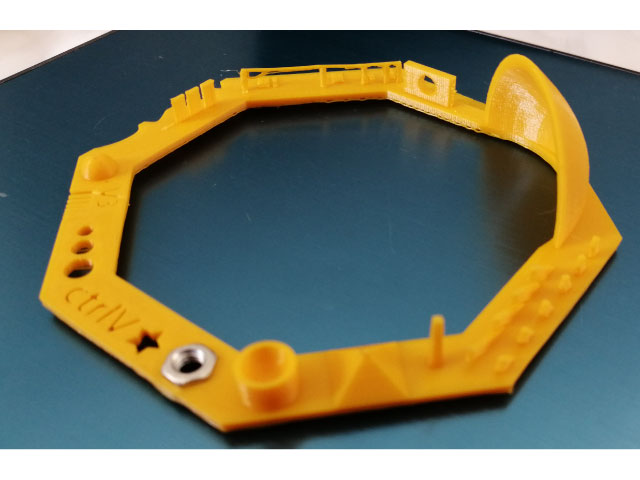
Test II
The Precision/Orverhang test was downloaded from thingiverse.
Settings:
Layer height: 0.15 mm
Wall thickness: 1 mm
Infill: 20%
Without supports or brim
Results:
Hole size (3 holes 4/6/8 mm): Good precision
Diameter Test (1 mm wall): 4 tubes 4/6/8/10 mm: Good precision
Support Overhang Test (10°/20°/30°/30°/40°/50°/60°/70°/80°): Below 60 good quality above 60 passing quality.
Bridging print (2/5/10/15/20/25 mm): Good quality
Surface (all the flat parts): Good
Pins test: 2 mm x 10 mm – 2 mm x 20 mm – 2 mm x 30 mm: passing quality
Individual Assignment:
3D Printing
Design I
For the individual assignment I decided to choose an element from my final project which are the planting pots.
I decided to create a parametric design for these pots using Rhinoceros software and Grashopper plugin.
The object that I want to design cannot be done subtractively. The pots have an organic pattern and design in which it cannot be created in any subtractive manufacturing method (cnc, laser machines, etc ...).
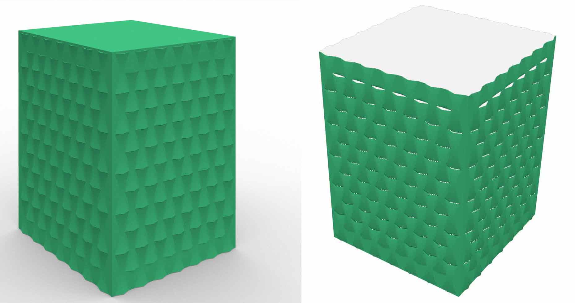
If we look at the two designs each has a different pattern. The first design has paremetric divisions along the surface with vertical openings to keep the soil breathing. In order to test this design I had to use additive manufacturing FDM 3D printing.
In the second design if we look at the pot it has an organic warped shape following the pattern of each side. The pattern and volume are inspired from the different shapes we run into in nature This pot has an organic shaped volume that also cannot be done in any other way than additive manufacturing.
About Rhinoceros Software
Rhinoceros is a 3D computer graphics and computer-aided design (CAD) modeling software used in a variety of ways and for very different purposes. It is a tool used primarily in surface-modeling, but has many other functions as well. Rhinoceros works with geometry based on NURBS (Non-uniform rational based spline) mathematical model that focuses on having a precise representation of curves and free form surfaces in computer graphics. Rhinoceros offers many options for creating digital models, some Rhinoceros users use the minimum of it, while others use a lot more, depending on the different applications to be accomplished. This software is used to create and edit different types of objects it is used to draw surfaces, poly-surfaces, solids, curves, and polygon meshes.
About Grasshopper
Grasshopper is a visual programming language and environment that runs within the Rhinoceros 3D computer-aided design (CAD) application. Grasshopper is primarily used to build generative algorithms, such as for generative art. Many of Grasshopper's components create 3D geometry. Programs may also contain other types of algorithms including numeric, textual, audio-visual, and haptic applications. Advanced uses of Grasshopper include parametric modelling for structural engineering, parametric modelling for architecture and fabrication. lighting performance analysis for eco-friendly architecture, and building energy consumption.
Grasshopper data tree
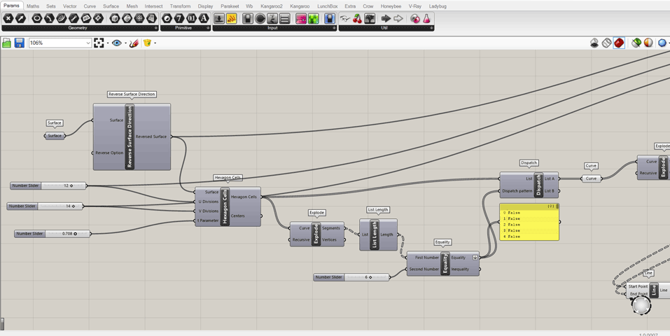
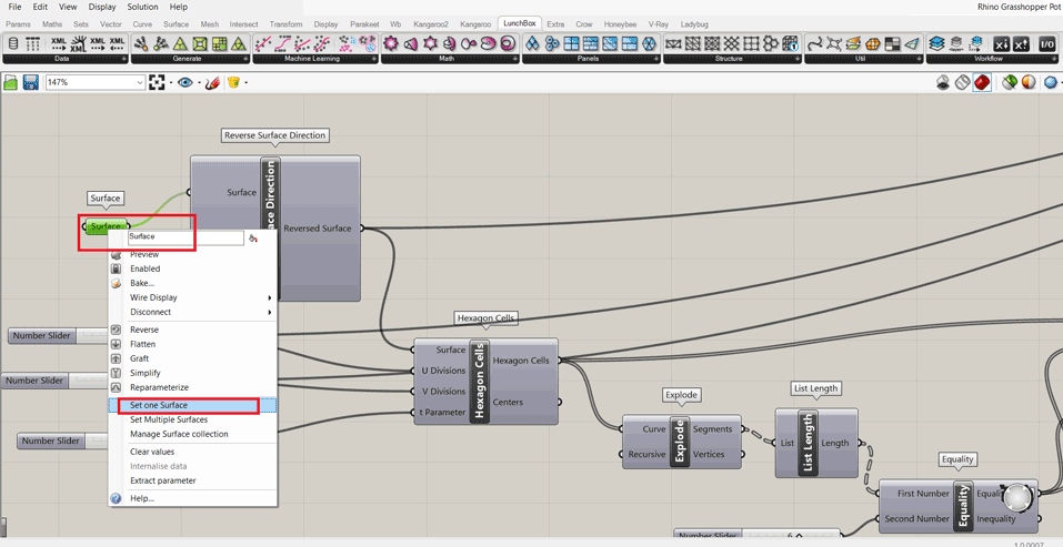
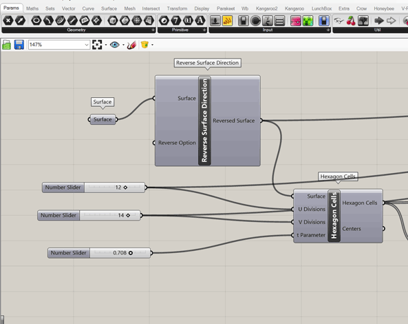
In rhinoceros I drew a rectangle 200 x 150 mm that will be my model dimensions.
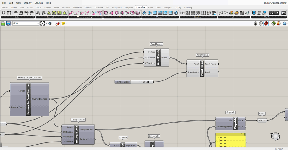
In Grasshopper using the command surfaces I selected the rectangle using select one surface then I indicated the number of cells U and V divisions parameters.
The divisions are 12 and 14.
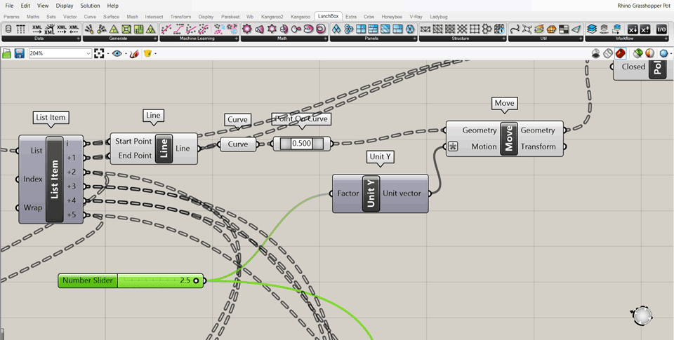
Then I decided to make a quad panels pattern on the surface.
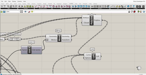
I had to make more divisions on the surface using explode command and Unit Y for indicating the number of divisions.
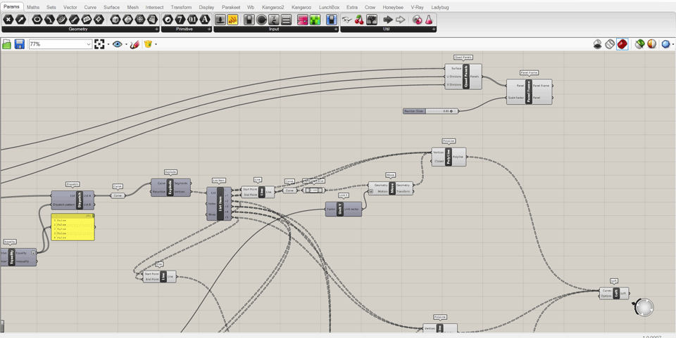
I downloaded Lunchbox extension for grasshopper. Lunchbox is used to create panels on a selected surface.
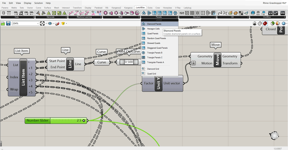
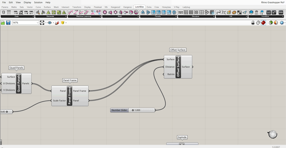
Using the panel frame and quad panels command I indicated the surface, scale factor, and the U V divisions.
In the final steps I did the loft command to create surfaces between the polylines that are the divisions.
Then using the command offset surface I gave the lofted surfaces some thickness 1 mm so we can 3D print it.
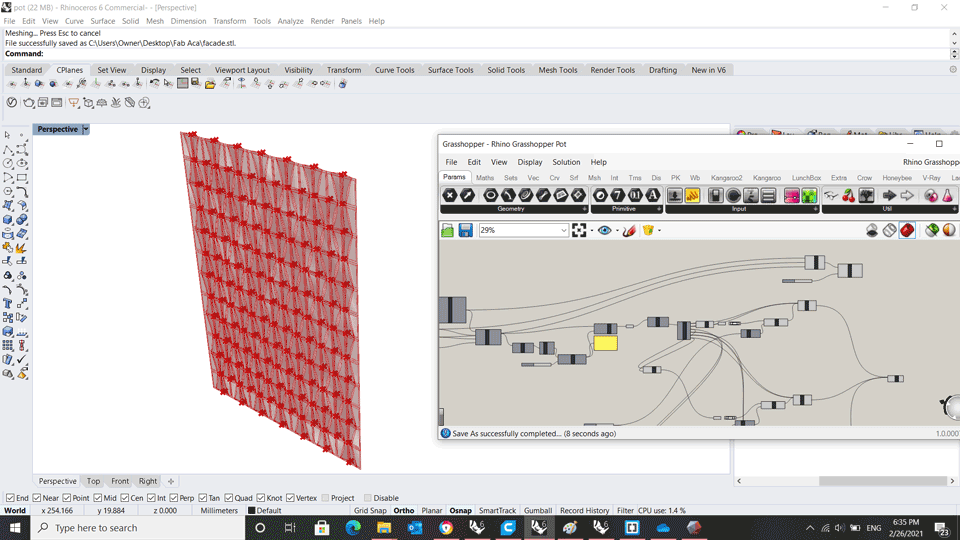
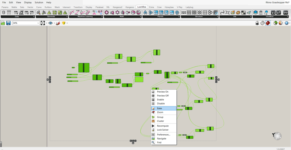
All the above steps are saved in grasshopper to take this model into rhinoceros and edit it their we have to bake the model.
Select all the grashopper data tree and right click bake.
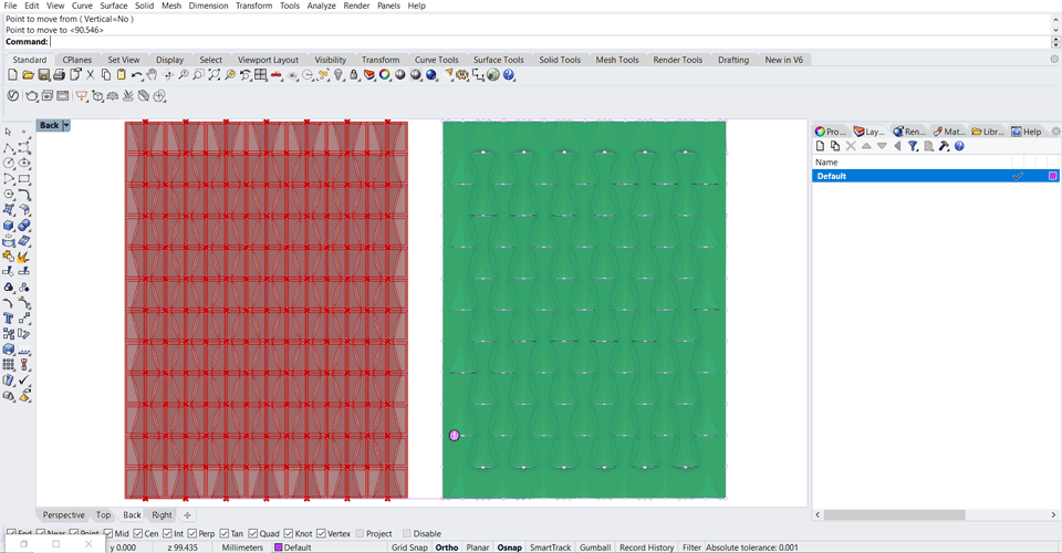
This design as shown in the above render has small openings to keep the soil breathing having an air flow without making the soil too humid since it will ruin the plants.
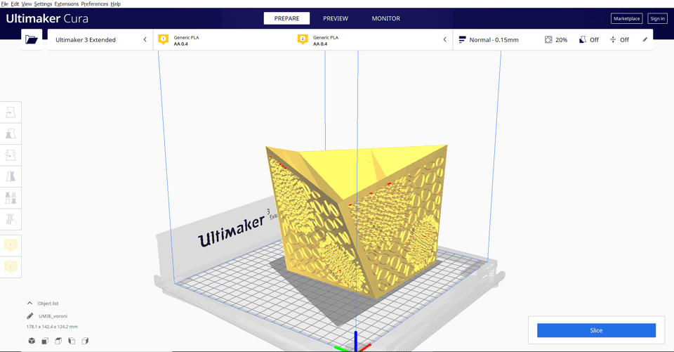
Design II
The second design I also used grasshopper to create voronoi patterns to have it as a design for the pots.
Voronoi patterns are a partition of a plane into regions close to each of a given set of objects. These objects are just points in the plane (called seeds, sites, or generators). For each seed there is a corresponding region, called Voronoi cells, consisting of all points of the plane closer to that seed than to any other. The Voronoi diagram of a set of points is dual to its triangulation.
I wanted to use voronoi patters because they are inspired from nature. It’s a mathematical cellular pattern that occurs in nature.
I created a surface 50 x 50 cm using the command plane surface and number sliders.
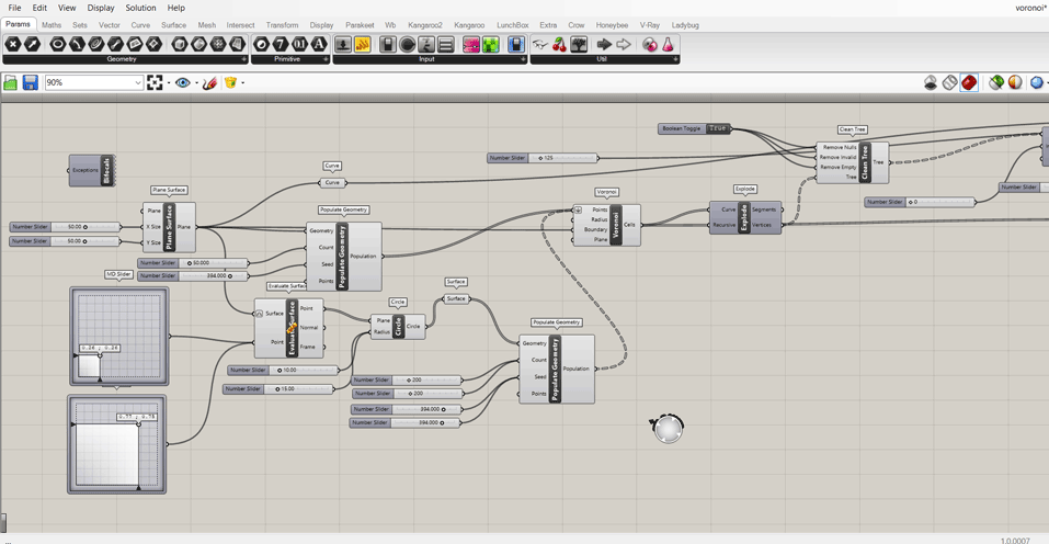
Then using the command MD slider, circle and populate geometry to start creating the pattern that should be on the surface and its location.
After assigning the pattern and surface we need to crate surfaces for the patterns and offset them.
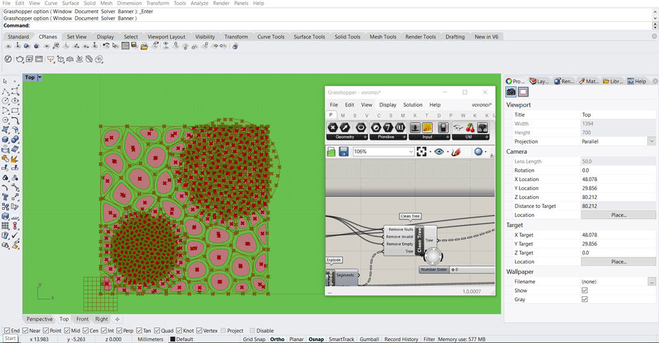
After checking the data tree select all and right click bake the model to edit it in rhinoceros.
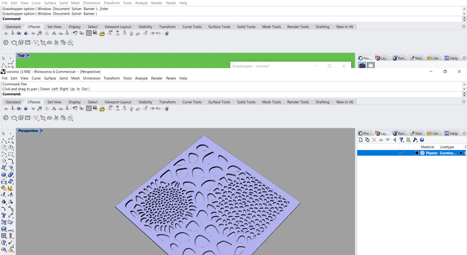
After baking the model we have it as surfaces in rhino.
To design the pot I created 3D surfaces using the command surface.
To apply the voronoi pattern on the new surface I used the command flow along surface choosing the pattern, thebase surface and thenew surface to be applied to.
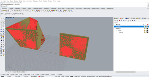
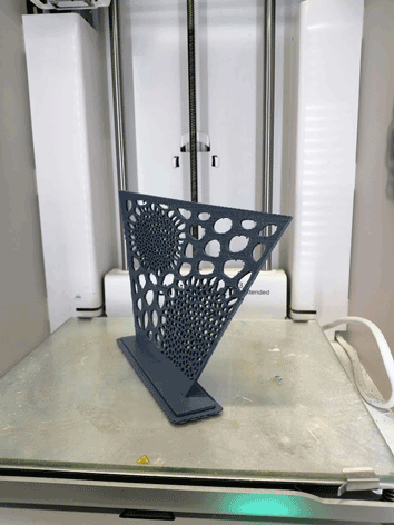
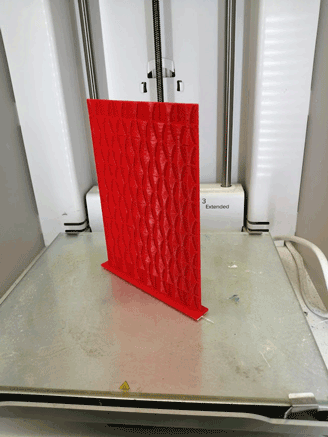
I 3D printed only one part of the pots to check the design of the pattern and if I need to adjust anything before printing the final design for the final project.
Printing Process
After fnishing all the needed edits we have to export the file as .stl.
An STL file stores information about your 3D model. The format represents the raw surface of a model with small triangles. The more complex and detailed the structure is, the more triangles will be used to represent the model.
There are two different ways for a file to store information: ASCII encoding and binary encoding. Binary format is way easier to read, which can be convenient when you need to inspect the file to find an eventual problem.
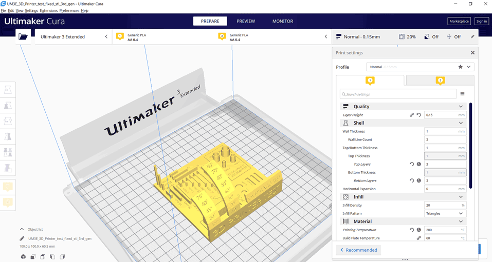
CURA Slicer
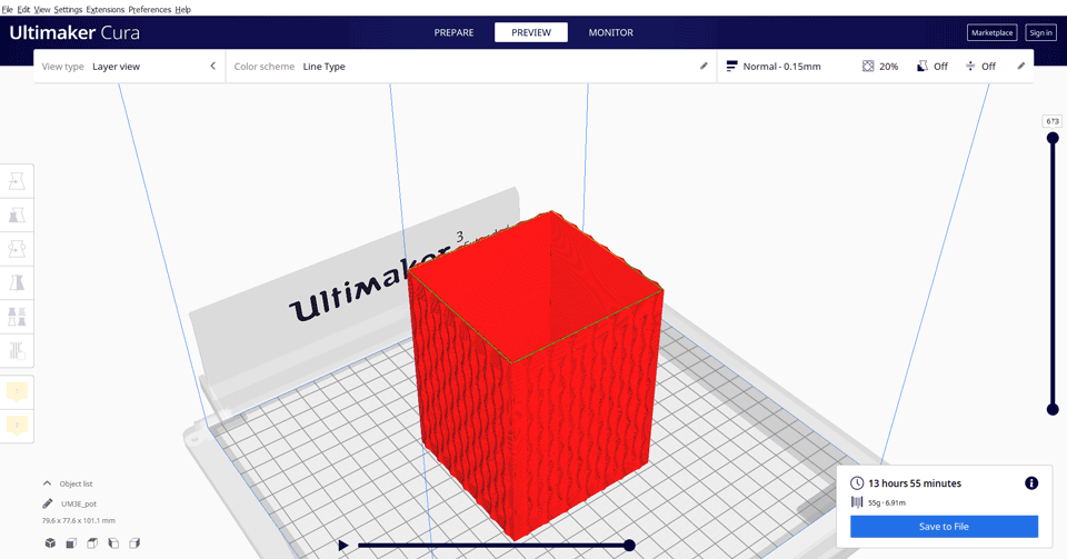
I will use cura slicer to assign the printing settings for the model as generate a Gcode.
In cura on the to left we have to choose the 3D printer we are going to use.
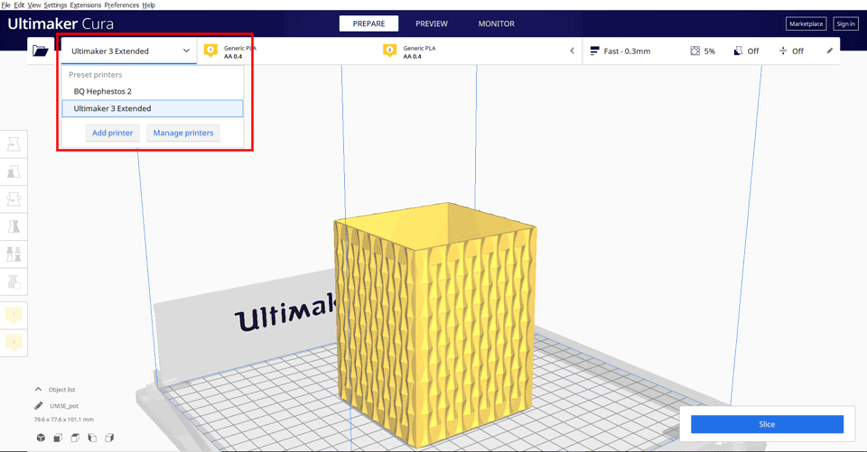
-Click on the folder to open and load the .stl file.
From the settings panel we have to choose the filaments we are going to use in the printing process.
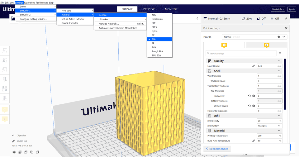
Moving to the settings in which we have to choose the quality of the print needed with many others.
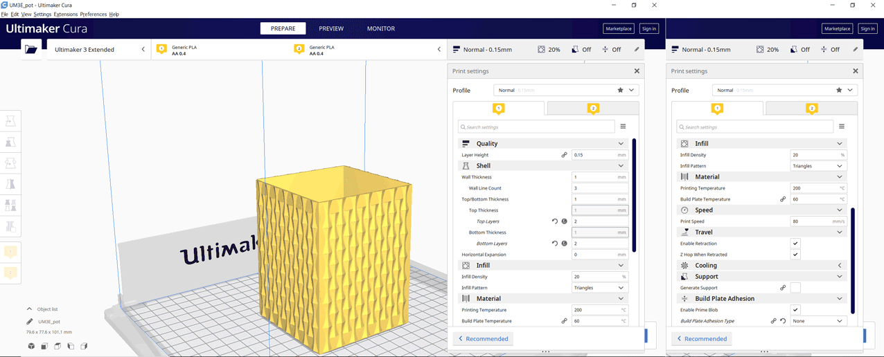
Quality - Layer height: 0.15mm
Shell - Wall thickness: 1mm
Infill - Infill Density; 20%
Infill - Infill Patern: triangles
Material for the PLA - Printing temperature: 200 deg C
Material - Build Plate temperature: 60 deg C
Speed - Print speed: 80 mm/s
Support - no need for supports
Build plate adhesion - Build plate adhesion type: raft
After checking the settings click on the preview and slice to show the sliced model layers, time needed to finish the print and amount of PLA needed.
3D Scanning
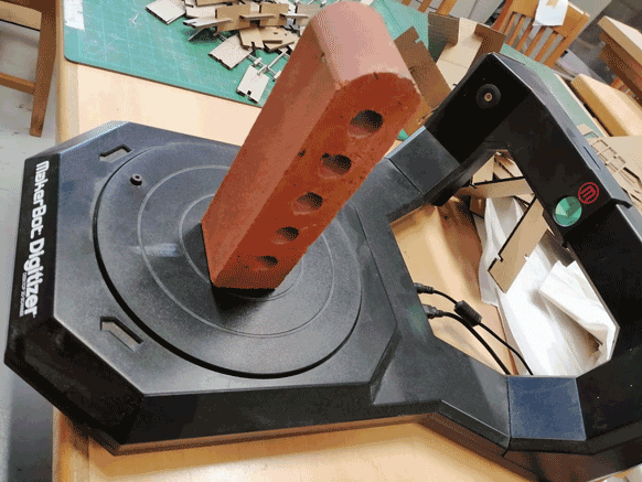
For this assignment I am going to use the Makerbot Digitzer 3D scanner to scan an object.
Desktop scanner
Scan Volume: 200 mm x 200 mm.
Supported File Types: STL, Thing.
I tried several objects that have different surfaces to check different results.
Shiny surfaces cannot be detected easily by the scanner having a bad surfaces as a final result.
Sometimes we have to change the color of the object by painting it.
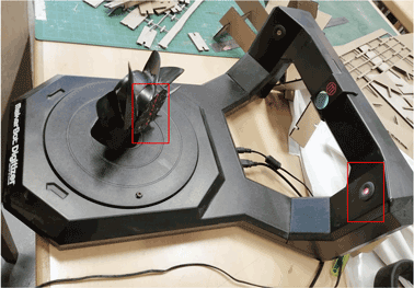
This scanner has a turnable plate that rotates while 3 laser beams are scanning the object.
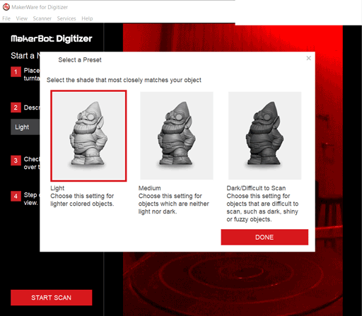
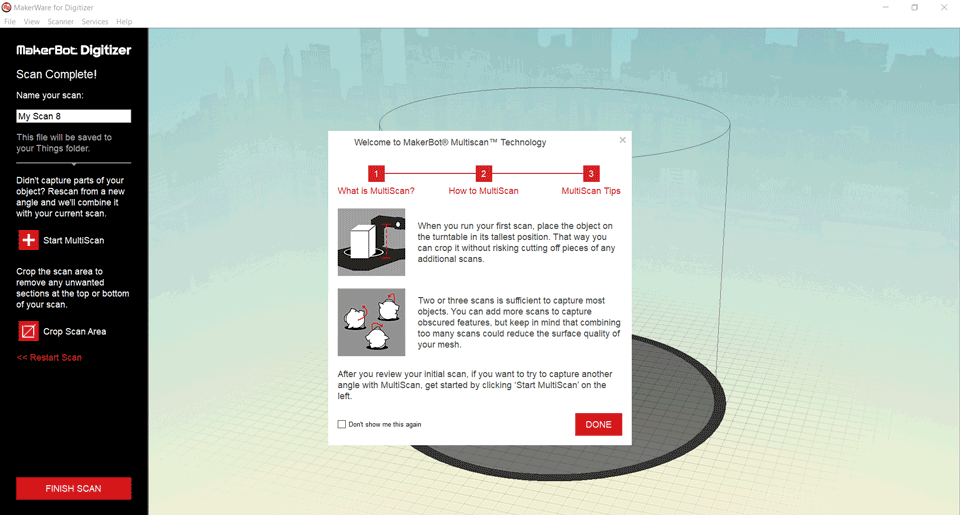
Using the software makerware for digitzer once we want to scan an object it will ask if the object is light, medium or hard/difficult to scan.
After selecting the preset we can now click on start scan and the plate will start rotating with the laser beam (red rectangle).
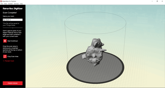
The scan took nine minutes total time.
The object has shiny surfaces so the scanner did some reflections preventing some areas from being scanned ending up having a mess.
I scanned another object that does not have shiny surfaces.
The final results are much better than the previous model.
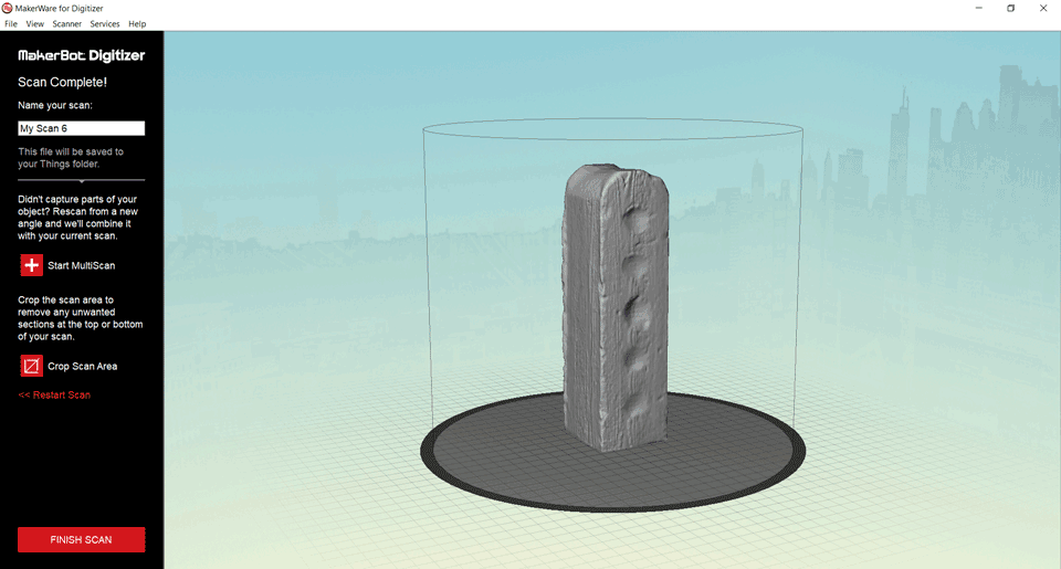
The solid file saved as .stl is saved then imported into any 3d modeling software for editing.
Here we can realize that the scanner did not detect the inner wholes of the object since the laser beams cannot reach them. We can edit the file and create the wholes using any 3D software.
Also we can do the multiscan option in which we can double scan the object in a different direction to reach surfaces that did not appear in the first scan. Some surfaces are deep and the laser beams cannot reach them so we need to rotate the object in another direction.

This work is licensed under a Creative Commons Attribution-NonCommercial-ShareAlike 4.0 International License