Group Assignment
Measure the power consumption of an output device.
Individual Assignment
Add an output device to a microcontroller board you've designed and program it to do something.
Individual Assignment
Output Devices
In this assignment we will be working on and testing some output devices.
I designed a new board using the ATmega328p micrcontroller and I chose to test an LCD I2C and a servo motor.
Examples of Output Devices:
LEDs
LCD
Speakers
Projectors
Stepper motors
Servo motors
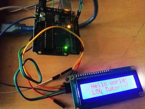
First I tested the output devices on Arduino Uno "Open Source" electronic hardware because in the board I will be designing I will use the same microcontroller.
Designing the Board
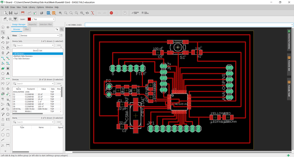
Eagle Board:
To design the board I used Eagle Software and as a reference Satshakit
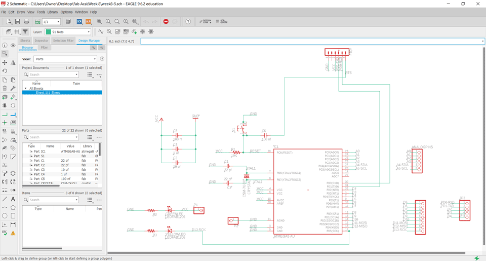
Components and their pins
Components:
ATmega328p
16 MHZ Crystal
Six capacitors: 2x 22 pf, 10 uf, 1 uf, 2 x 100 nf
Three resistors: 10K, 499 ohm, 100 ohm
LEDs: Red and Green
FTDI Connection
Switch
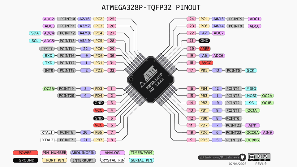
Explanation:
Pin4,6,18: VCC connected to the supply voltage.
Pin7-8: PB6-PB7 XTAL1-XTAL2 are connected to the crystal.
Pin 3-5-21: are connected to the ground.
Pin29: PC6 is connected to the reset.
Pin17: PB5 SCK is connected to the LED.
Pin15: PB3 MOSI digital pin.
Pin16: PB4 MISO digital pin.
Pin30: PD0 is connected to the RXD.
Pin31: PD1 is connected to the TXD.
Pin27: PC4 is analog pin connected to the SDA.
Pin28: PC5 is analog pin connected to the SCL.
A0-A7 are analog pins.
D0-D13 are digital pins.
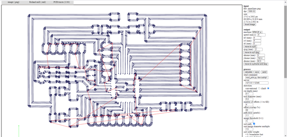
Exported traces and Gcode
Milling the board:
I used fabmodules to extract the gcodes.
Electronics Production refer to electronics production assignment for more details.
Exported inner traces, the drilling and the cuting image:
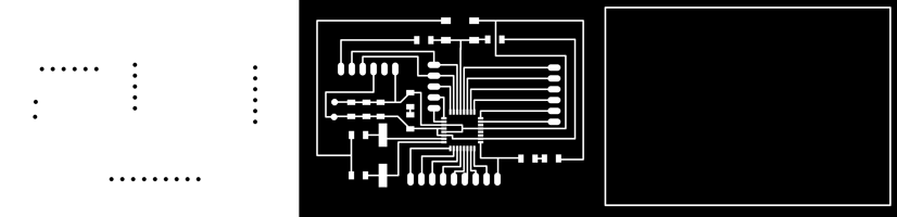
Gcode:
Milling:
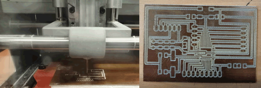
Soldering:
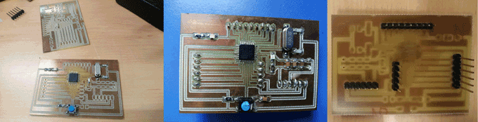
Testing Ouput Devices
LCD Screen
LCD 16 x 2 Digital display
Connections:
GND connected to GND
VCC connected to VCC
SDA connected to pin A4
SDL connected to pin A5
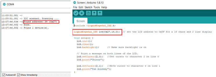
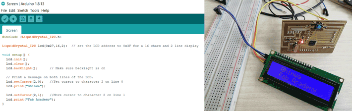
First step we have to find the address of the connected device the LCD I2C.
In arduino the tools tab in the serial monitor we can see that it is scanning to check the address. I will copy it and paste in the code to send commands to the LCD.
Code:
by Ghinwa Azzi Fab Academy 2021
#include

LiquidCrystal_I2C lcd(0x27,16,2);  // set the LCD address to 0x3F for a 16 chars and 2 line display

void setup() {
  lcd.init();
  lcd.clear();
  lcd.backlight();      // Make sure backlight is on

  // Print a message on both lines of the LCD.
  lcd.setCursor(2,0);   //Set cursor to character 2 on line 0
  lcd.print("Ghinwa");

  lcd.setCursor(2,1);   //Move cursor to character 2 on line 1
  lcd.print("Fab Academy");
}
First I tested the LCD using Arduino UNO then I connected it to my board.
Servo Motor
Connections:
GND connected to GND
VCC connected to VCC
Signal connected to Digital PIN 9
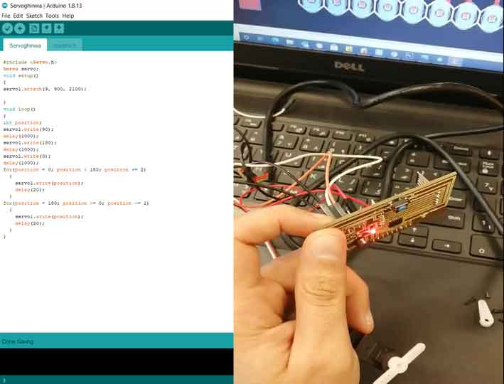
Code:
By Ghinwa Azzi Fab Academy 2021
#include

Servo servo;
void setup()
{
servo1.attach(9, 900, 2100);

}
void loop()
{
int position;
servo1.write(50);
delay(1000);
servo1.write(100);
delay(1000);
servo1.write(0);
delay(1000);
for(position = 0; position < 100; position += 2)
  {
    servo1.write(position);
    delay(20);
  }
for(position = 100; position >= 0; position -= 1)
  {
    servo1.write(position);
    delay(20);
  }
}
In the above code the servo will turn at a certain angles 0 and 100 degrees.
Group Assignment
Here you can find our group assignment LINK
Output Devices
The objective of this week is to get introduced to using output devices. Output devices could be anything that converts a signal received from a microcontroller into something sensible, such as a light, motion, representing something on an LCD and many more. There are many output devices in the market that could be used to connect the microcontroller to the outside world. Those output devices could be an LED, a voltage relay, an LCD, a Stepper or Servo motor and many more. Technically everything that allows you to know what is happening inside the circuit or what provides motion to a system. In this section, we will learn on how to use and connect an output device to a microcontroller, and how to use it to produce motion and save data that is collected using sensors from its surrounding.
Group Assignment
The group assignment was to Measure the power consumption of an output device.
An output device is any device used to send data from a computer to another device or user. Most computer data output that is meant for humans is in the form of audio or video. Thus, most output devices used by humans are in these categories. Examples include monitors, projectors, speakers, headphones and printers.
Machines used in this assignment:
- Roland MDX-40 is the Desktop CNC machine used to mill copper boards.
- Tektonix TBS 1052B is the oscilloscope used to observe the operation of the microcontroller circuit board.
- National Instruments VirtualBench was used as a digital oscilloscope to observe and document the operation of the microcontroller circuit board.
- FLUKE 179 was the multimeter used throughout all the process.
- ProsKit SS 207 was the soldering iron used for welding the components.
Measuring the power consumption of an output device
The group assignment is to measure the power consumption of an output device:
We decided to measure the current and power consumption of one of An LCD display. To do that we used a "Fluke" Multimeter and we placed the prob in Ampere. As you can mention the current value is 571 mA, knowing that the we are powering it using Arduino.
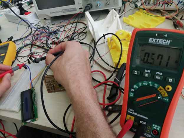
Power = Tension x Current
P(W)= 5 (V) x 0.571 (A)
P = 2.855 Watts

This work is licensed under a Creative Commons Attribution-NonCommercial-ShareAlike 4.0 International License