Group Assignment
Compare the performance and development workflows for other architectures.
Individual Assignment
Read a microcontroller data sheet, program your board to do something, with as many different programming languages and programming environments as possible.
Individual Assignment
Definition of Microcontrollers
Microcontrollers also referred to as MCUs (microcontroller units), are embedded semiconductor devices used in circuit board design.
Microcontrollers are mostly used in single-function ’embedded’ applications.
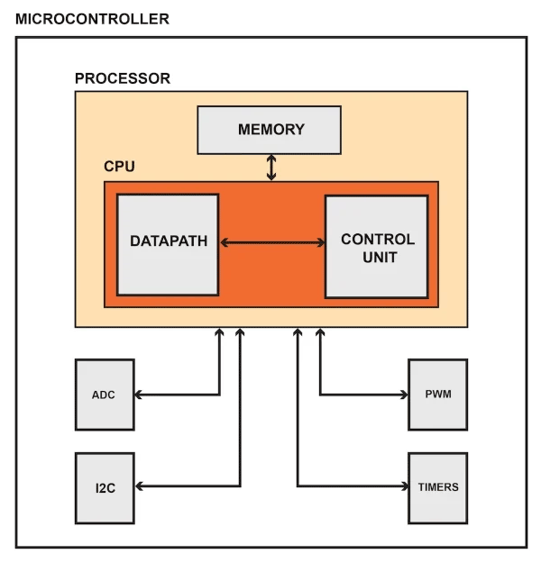
Microcontrollers contain single or multiple processors (sometimes referred to as CPUs), plus memory and I/O peripherals. These peripherals include timers, ADCs (analogue-to-digital converters) and DACs (digital-to-analogue converters).
Microcontrollers are 8 or 16 bit microprocessors.
They usually have low-power requirements since many devices they control are battery-operated.
Definition of Microprocessors
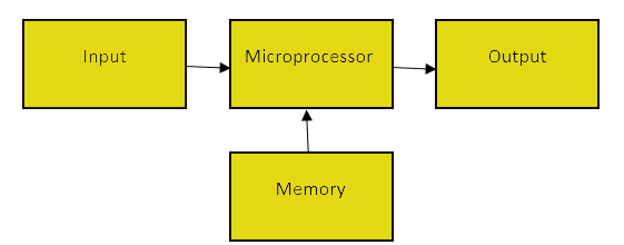
Microprocessor is a type of miniature electronic device that contains the arithmetic, logic, and control circuitry necessary to perform the functions of a digital computer’s central processing unit.
Microprocessors work as CPU (central processing unit) of the computer.
It is the central unit of a computer system that performs arithmetic and logic operations, which generally include adding, subtracting, transferring numbers from one area to another, and comparing two numbers.
A microprocessor accepts binary data as input, processes that data, and then provides output based on the instructions stored in the memory.
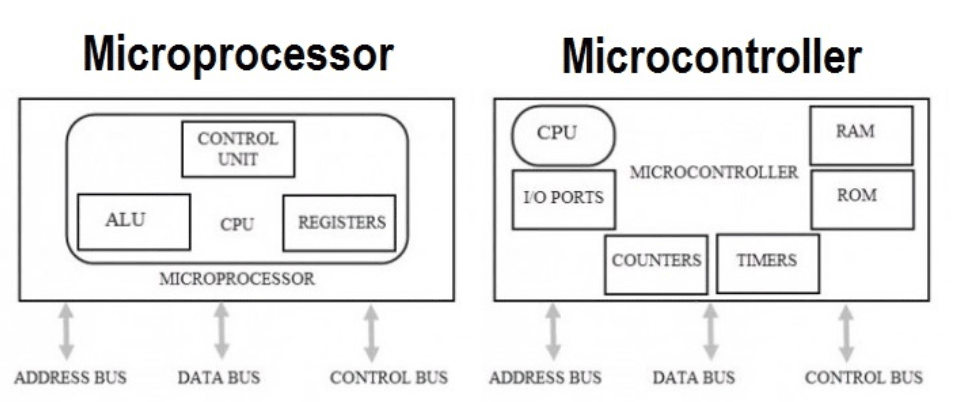
Difference between Microprocessors and Microcontrollers
Microprocessor consists of only a Central Processing Unit, whereas Micro Controller contains a CPU, Memory, I/O all integrated into one chip.
Microprocessor uses an external bus to interface to RAM, ROM, and other peripherals, on the other hand, Microcontroller uses an internal controlling bus.
Microprocessor is complicated and expensive, with a large number of instructions to process but Microcontroller is inexpensive and straightforward with fewer instructions to process.
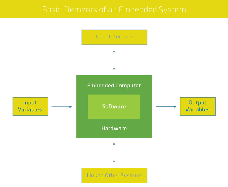
Definition of Embedded Systems
An embedded system is a microprocessor- or microcontroller-based system of hardware and software designed to perform dedicated functions within a larger systems.
Types of Microcontrollers
8 bit Microcontroller
16 bit Microcontroller
32 bit Microcontroller
Embedded Microcontroller
External memory Microcontroller
AVR Microcontrollers
An AVR microcontroller is a type of device manufactured by Atmel, which has particular benefits over other common chips.
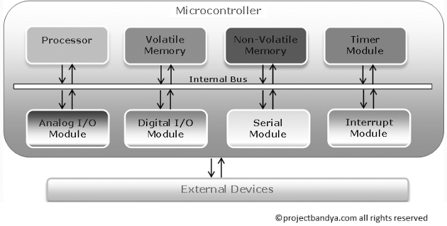
Components of a microcontroller:
Processor: The processor refers to the Central Processing Unit (CPU) of the microcontroller. It contains the Arithmetic Logic Unit (ALU), Control Unit, Instruction Decoder and some Special Registers (Stack Pointer, Status Register, Program Counter, etc.).
Volatile Memory: This is memory used by ht microcontroller for temporary data storage, system setup and peripherals configurations. Memory in this category includes SRAM and DRAM. AVR microcontrollers utilize SRAM.
Non-Volatile Memory: This is memory used by the microcontroller to store programs. Data can also be stored in this memory but the access time is much slower than that of RAM. Memory in this category includes ROM, PROM, EPROM, EEPROM and FLASH. The AVR microcontrollers utilize Flash for program storage, some AVR controllers contains a bit of EEPROM as well.
Timer Module: Most microcontrollers have at least one timer/counter peripheral. Timer/Counter modules are used to perform timing or counting operations in the controller. These include time stamping, measuring intervals, counting events, etc.
Interrupt Module: Interrupts enable the microcontroller to monitor certain events in the background while executing and application program and react to the event if necessary pausing the original program. This is all coordinated by the interrupt module.
Digital I/O Module: This module allows digital/logic communication with the microcontroller and the external world. Communication signals are that of TTL or CMOS logic.
Analog I/O Modules: These modules are use to input/output analog information from/to the external world. Analog modules include Analog Comparators and Analog-to-Digital Converters.
Serial Modules - These modules are used for serial communication with the external world. An example is the USART peripherial which utilizes the RS232 standard.
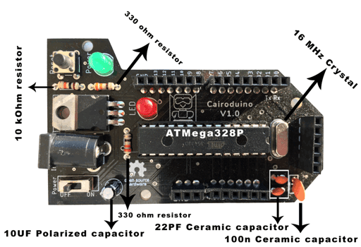
In this assignment I am going to use the ATMega328P Microcontroller.
ATMega328P Microcontroller
After checking the datasheet I concluded the below:
It is a high performance, low power AVR 8-bit microcontroller.
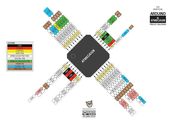
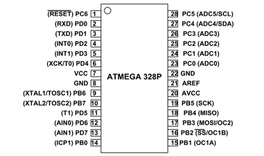
Pins of ATMega328P
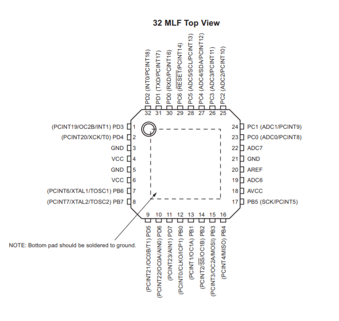
Descriptions:
- VCC: Digital supply voltage.
GND: Ground.
Port B: XTAL1 and XTAL2
Port B is an 8-bit bi-directional I/O port. As inputs, port B pins that are externally pulled low will source current if the pull-up resistors are activated. The Port B pins are tri-stated when a reset condition becomes active, even if the clock is not running.
Port C: is a 7-bit bi-directional I/O port. As inputs, Port C pins that are externally pulled low will source current if the pull-up resistors are activated. The port C pins are tri-stated when a reset condition becomes active, even if the clock is not running.
PC6: reset pin, PC6 is used as an input pin.
Port D: Port D is an 8-bit bi-directional I/O port. As inputs, port D pins that are externally pulled low will source current if the pull-up resistors are activated. The port D pins are tri-stated when a reset condition becomes active, even if the clock is not running.
AVCC: AVCC is the supply voltage pin for the A/D converter, PC3:0, and ADC7:6. It should be externally connected to VCC, even if the ADC is not used. If the ADC is used, it should be connected to VCC through a low-pass filter. Note that PC6..4 use digital supply voltage, VCC.
AREF: AREF is the analog reference pin for the A/D converter.
ADC7: ADC7:6 serve as analog inputs to the A/D converter. These pins are powered from the analog supply and serve as 10-bit ADC channels.
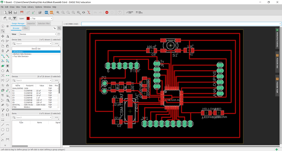
Eagle Board:
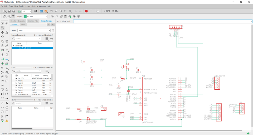
Explanation:
Pin4,6,18: VCC connected to the supply voltage.
Pin7-8: PB6-PB7 XTAL1-XTAL2 are connected to the crystal.
Pin 3-5-21: are connected to the ground.
Pin29: PC6 is connected to the reset.
Pin17: PB5 SCK is connected to the LED.
Pin15: PB3 MOSI digital pin.
Pin16: PB4 MISO digital pin.
Pin30: PD0 is connected to the RXD.
Pin31: PD1 is connected to the TXD.
Pin27: PC4 is analog pin connected to the SDA.
Pin28: PC5 is analog pin connected to the SCL.
A0-A7 are analog pins.
D0-D13 are digital pins.
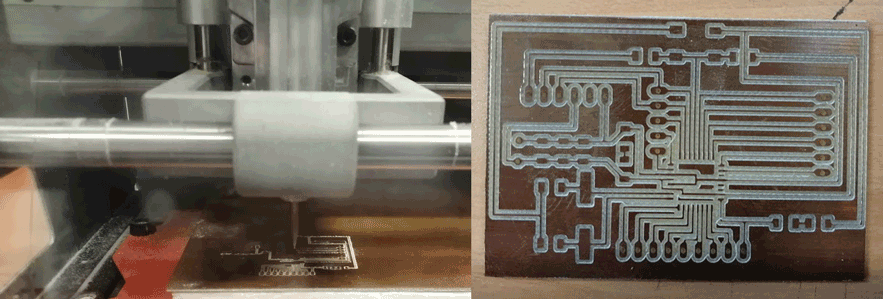
Milling the board:
I used fabmodules to extract the gcodes.
Electronics Production refer to electronics production assignment for more details.
Programming using Arduino
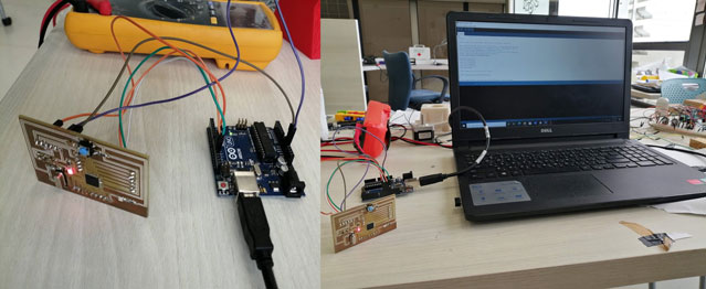
Connections:
MOSI on my board connected to Pin 11 on Arduino - red cable
MISO on my board connected to Pin 12 on Arduino - orange cable
RST on my board connected to Pin 10 on Arduino - white cable
SCK on my board connected to Pin 13 on Arduino - green cable
GND on my board connected to GND Pin on Arduino - purple cable
VCC on my board connected to VCC Pin on Arduino - brown cable
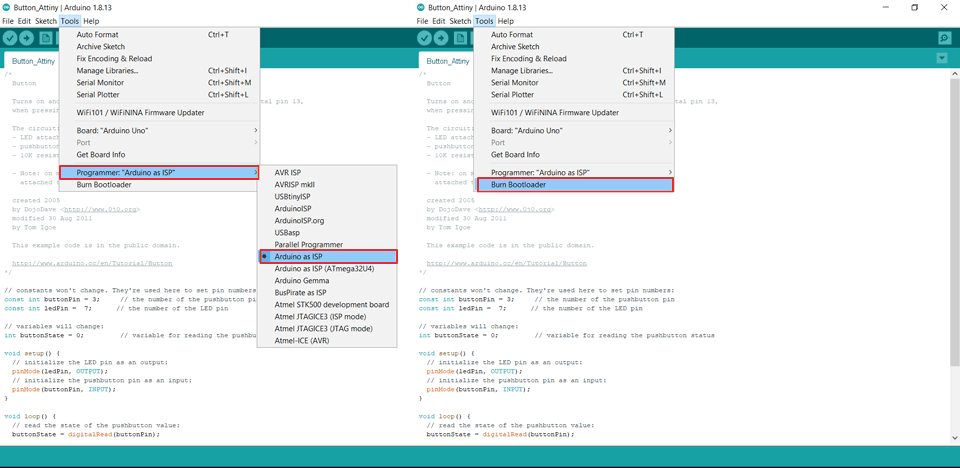
Arduino Setup:
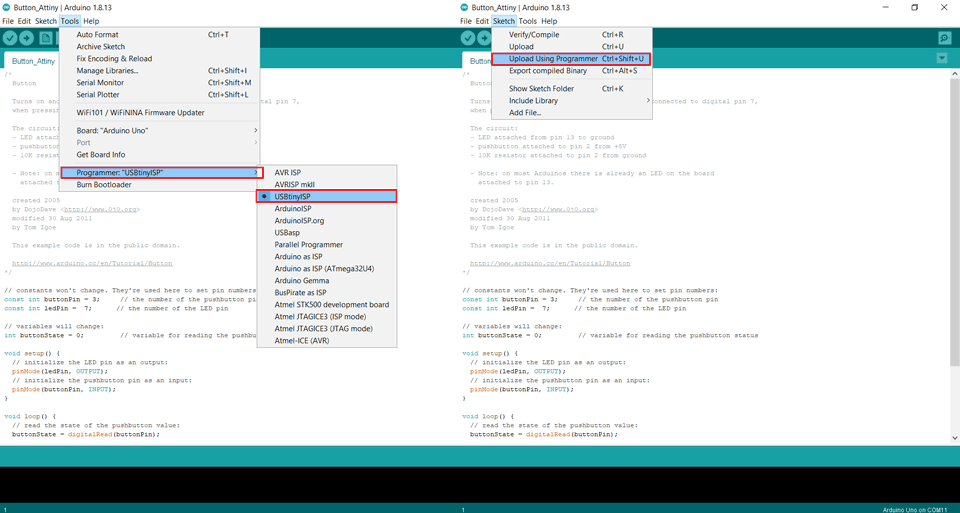
Since we are using the ATmega328P we don't need to install the Attiny program, set the Board ,the processors and the clock since it is the same microcontroller as the arduino.
We will set the programmer as "Arduino as ISP"
To program my board for the first time or reset it we will go to tools then burn bootloader.
As I am new and exploring the world of electronics while connecting my board that I designed several mistakesn appeared that I noted so not to repeat in the future projects:
First I did not include an ISP pinhead and connect to the reset pin to the push button. So we had to create a jumper in order to do bootloader.
Second problem was that I switched the pins of TXD and RXD. So when I connected the FTDI cable we had to switch the wires in order to upload the codes.
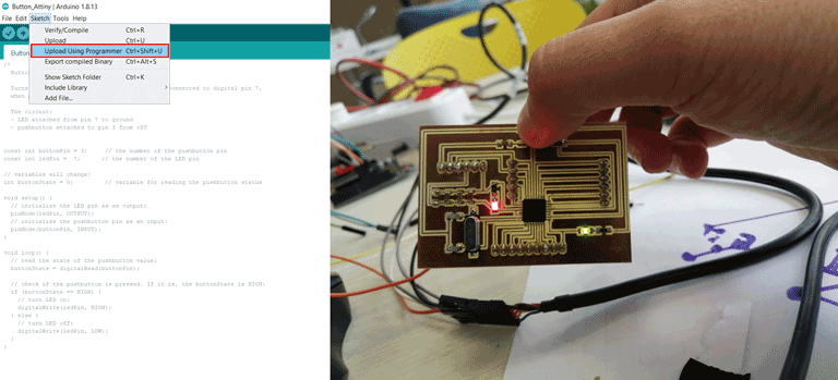
Programs
After writing the code we have to upload it by clicking on sketch then upload using programmer option.
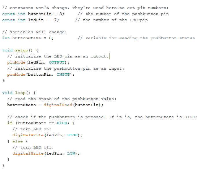
Program I: LED on-off
The green LED should light when I push the button and turn off when I release the button.
Pins:
LED pin is Pin7 on the Arduino baord.
Button pin is Pin3 on the Arduino board.
                             /*
  Button

  Turns on and off a light emitting diode(LED) connected to digital pin 13,
  when pressing a pushbutton attached to pin 2.

  The circuit:
  - LED attached from pin 7 to ground through 220 ohm resistor
  - pushbutton attached to pin 3 from +5V

  created 2005
  by DojoDave
  modified 30 Aug 2011
  by Tom Igoe
  Modified by Ghinwa Azzi Fab Academy 2021

  This example code is in the public domain.

  https://www.arduino.cc/en/Tutorial/BuiltInExamples/Button
*/

// constants won't change. They're used here to set pin numbers:
const int buttonPin = 3;     // the number of the pushbutton pin
const int ledPin =  7;      // the number of the LED pin

// variables will change:
int buttonState = 0;         // variable for reading the pushbutton status

void setup() {
  // initialize the LED pin as an output:
  pinMode(ledPin, OUTPUT);
  // initialize the pushbutton pin as an input:
  pinMode(buttonPin, INPUT);
}

void loop() {
  // read the state of the pushbutton value:
  buttonState = digitalRead(buttonPin);

  // check if the pushbutton is pressed. If it is, the buttonState is HIGH:
  if (buttonState == HIGH) {
    // turn LED on:
    digitalWrite(ledPin, HIGH);
  } else {
    // turn LED off:
    digitalWrite(ledPin, LOW);
  }
}
In the above modified code I changed the button and LED pins according to my board design.
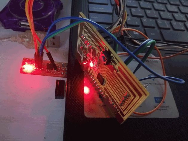
Uploading and testing the Code:
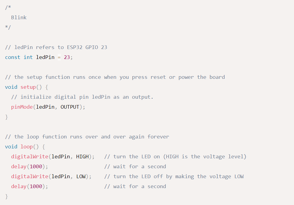
Program II: Blinking LED
The green LED on for one second, then off for one second, repeatedly when we click the button.
Pins:
LED pin is Pin7 on the Arduino baord.
Button pin is Pin3 on the Arduino board.
/*
Colby Newman (Sept 2016)
Modified by Ghinwa Azzi Fab Academy 2021
  Blink

  Turns an LED on for one second, then off for one second, repeatedly.

  http://www.arduino.cc/en/Tutorial/Blink
*/

const int buttonPin = 3;     // the number of the pushbutton pin
const int ledPin =  7;      // the number of the LED pin

void setup() {
  // initialize digital pin LED_BUILTIN as an output.
  pinMode(LED_BUILTIN, OUTPUT);
}

// the loop function runs over and over again forever
void loop() {
  digitalWrite(LED_BUILTIN, HIGH);   // turn the LED on (HIGH is the voltage level)
  delay(1000);                       // wait for a second
  digitalWrite(LED_BUILTIN, LOW);    // turn the LED off by making the voltage LOW
  delay(1000);                       // wait for a second
}
Initial author of the code is Colby Newman (Sept 2016) and I modified the code for the purpose of Fab Academy 2021 exercise by adding the push button and changing the pins to fit my board design.
Uploading and testing the Code:
Programming using FABISP
To connect the board to the FABISP we will connect each Pin on a board with its similar Pin on the other board.
Programming using C Language
Registers are the only way of interaction for a microprocessor.
Example:
ATmega328P needs to know how you are using its pins.
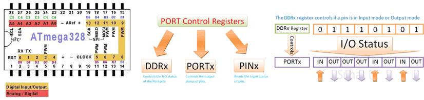
AVR microcontrollers having four I/O ports named as PORTA, PORTB, PORTC, PORTD.
ATMEGA microcontrollers have four I/O ports and each port having 8 I/O lines and totally each controller having 32 I/O lines.
These 32 I/O lines are bi-directional means we can use these I/O lines either input or output.
In my case I will be using the ATmega328 microcontroller. For example in this microcontroller pins 2-13 are PORTD.
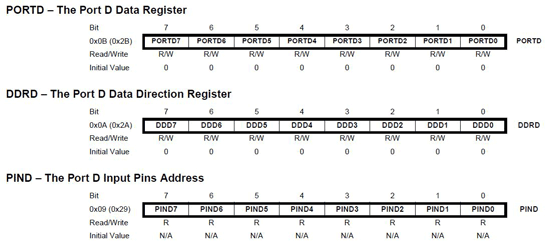
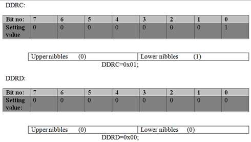
So if we want to configure PORTD, we need to configure DDRD, PORTD and PIND registers.
Write a 1 to make a pin an output and a 0 to make it an input.
PD0 to PD3 will be outputs, while PD4 to PD7 will be inputs. PD0 corresponds to DDD0 in the DDRD register. The other pins follow the same pattern as PD0.
DDRD = 0b00001111
PORTD = 0b11110000
To make all pins of port D as input pins: DDRD = 0b00000000
To make all pins of port D as ouput pins: DDRD = 0b11111111
To write the code I checked some online support.
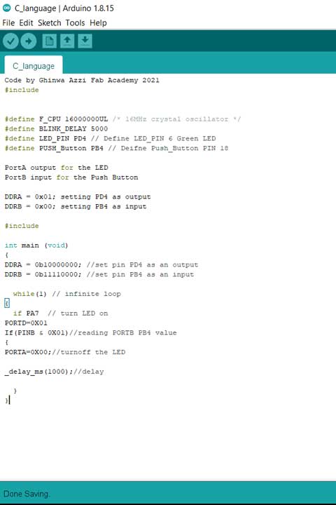
Writing the Code:
The below code is for one LED connected to PORTC and one button to PORTD.
Code by Ghinwa Azzi Fab Academy 2021
#include


#define F_CPU 16000000UL /* 16MHz crystal oscillator */
#define BLINK_DELAY 5000
#define LED_PIN PD4 // Define LED_PIN 6 Green LED
#define PUSH_Button PB4 // Deifne Push_Button PIN 18

PortA output for the LED
PortB input for the Push Button

DDRA = 0x01; setting PD4 as output
DDRB = 0x00; setting PB4 as input

#include

int main (void)
{
DDRA = 0b10000000; //set pin PD4 as an output
DDRB = 0b11110000; //set pin PB4 as an input

  while(1) // infinite loop
{
  if PA7  // turn LED on
PORTD=0X01
If(PINB & 0X01)//reading PORTB PB4 value
{
PORTA=0X00;//turnoff the LED

_delay_ms(1000);//delay

  }
}
Explaining the steps:
By checking the DDRx register we will set the inputs and outputs.
After we will set the pins as low or high by using PORTx register.
We will assign PORTA as onput and PORTB as input. Pin PB3 will be the input pin and Pin PA7 will be the output pin.
By using DDRA and DDRB registers we will configure these two pins one is output and one is input .
DDRA = 0x01; setting PA7 as output
DDRB = 0x00; setting PB3 as input
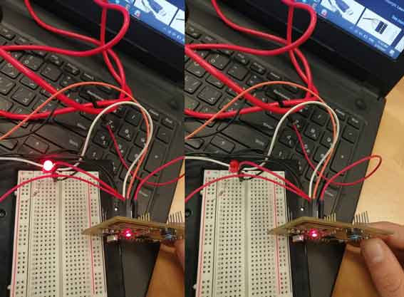
Uploading and testing the Code:
Group Assignment
Here you can find our group assignment LINK
In this assignment we will compare the performance and development workflows for other architectures.
AVR (ATmega328P)
The ATmega328 is a single-chip microcontroller created by Atmel in the megaAVR family. It is based on a modified Harvard architecture 8-bit RISC processor core.
Specifications:
I/O and packages:
- 23 programmable I/O lines
- 32-lead TQFP, and 32-pad QFN/MLF
Operating voltage:
- 2.7V to 5.5V for ATmega328P
Speed grade:
- 0 to 8MHz at 2.7 to 5.5V (automotive temperature range: –40°C to +125°C)
Low power consumption:
- Active mode: 1.5mA at 3V - 4MHz
8 bits and max speed 16 MHz
Architecture Harvard
Programming Environment
Arduino IDE
Example code for LED connected to a button
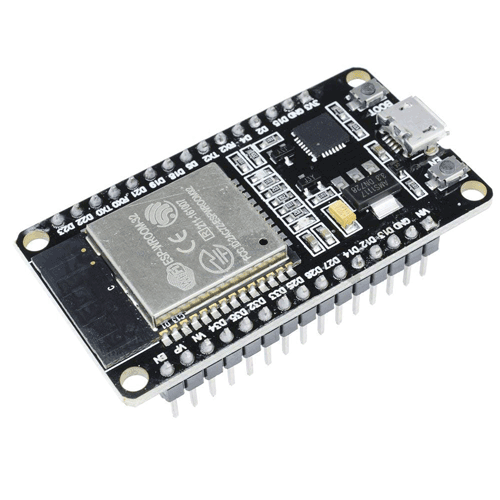
ESP 32
ESP32 is a series of low-cost, low-power system on a chip microcontroller with integrated Wi-Fi and dual-mode Bluetooth. The ESP32 series employs a Tensilica Xtensa LX6 microprocessor in both dual-core and single-core variations and includes built-in antenna switches, RF balun, power amplifier, low-noise receive amplifier, filters, and power-management modules.
Specifications:
I/O and packages:
- 39 programmable I/O lines
Operating voltage:
- 3.3 V
Frequency 40 MHz
Architecture Harvard
32-bit programs
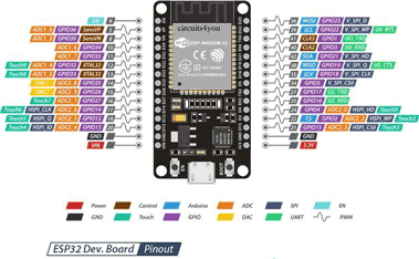
Programming Environment
Arduino IDE or JavaScript

This work is licensed under a Creative Commons Attribution-NonCommercial-ShareAlike 4.0 International License