Group Assignment
Use the test equipment in your lab to observe the operation of a microcontroller circuit board.
Individual Assignment
Redraw an echo hello-world board, add (at least) a button and LED (with current-limiting resistor),check the design rules, make it, and test it.
Individual Assignment
IDEA
I will redraw and make a hello-world board including LED light and a push button. The LED light will be connected on the output pin and the push button will be connected on the input pin. The main idea is all based on the original schematic hello-world board that includes the below components.
ATtiny44 (1)
Resonator 20MHZ (1)
Resistor 10K (2)
Capacitor 10 uf (1)
ISP header (1)
FTDI header (1)
In my hello-world board I will include two new components in addition to the basic ones mentioned above so it will include:
ATtiny44 (1)
Resistor 10K (2)
Resistor 100 ohm (1)
Capacitor 10 uf (1)
Capacitor 10 pf (2)
red LED (1)
Switch button
ISP header (1)
FTDI header (1)
Eagle Sketch
For this assignment I used Eagle software.
Steps to create the schematic design:
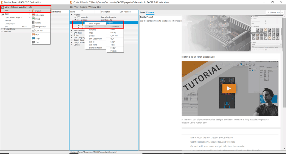
Launch EAGLE then start a new Project and create a new Schematic.
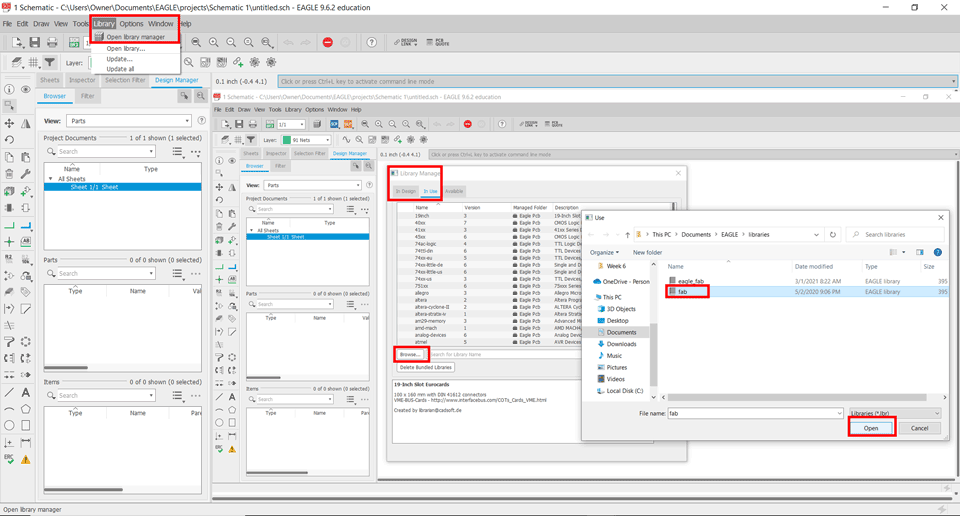
Then download the fab library and add it to the EAGLE libraries. In Eagle click on library / open library manager/ In Use / Browse for the fab.lbr file.
On the left side we have the Add Part command we will use it to start adding the parts to our schematic.
When we click Add Part the library will open and we will choose the fab library we added to search for the components needed.
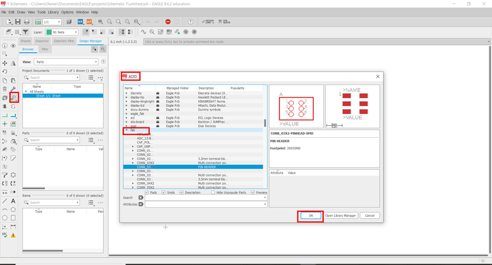
We will do the same step for all the components.
Once we add all the components we need to connect them to each other.
.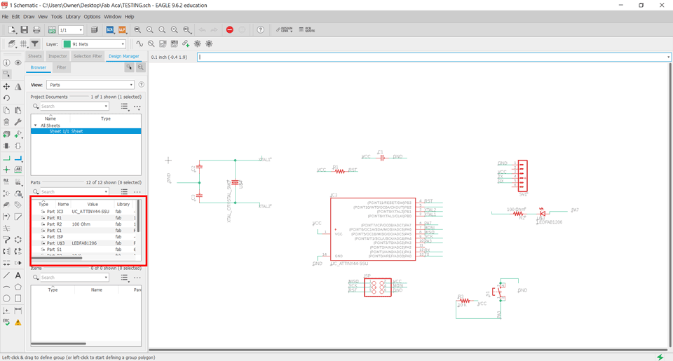
To connect the components we have two ways:
First way:Click on net command and place a net wire from one component to another.
Second way: Click on net command place a net wire then click on label and place it on the wire after right click on it to name it.
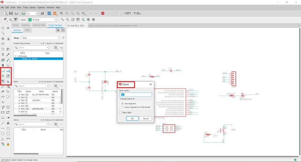
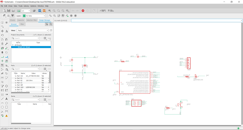
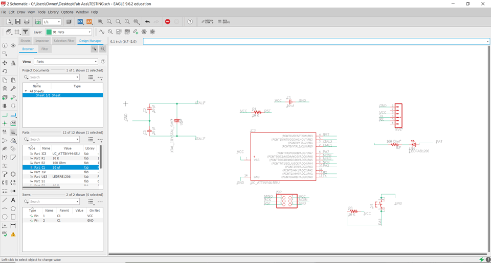
Using the second way is easier to visualize without using a lot of wires. This is my final schematic.
Components Datasheets and Explanation
The MicroController Unit ATtiny 44 as per the datasheet has the below configurations:
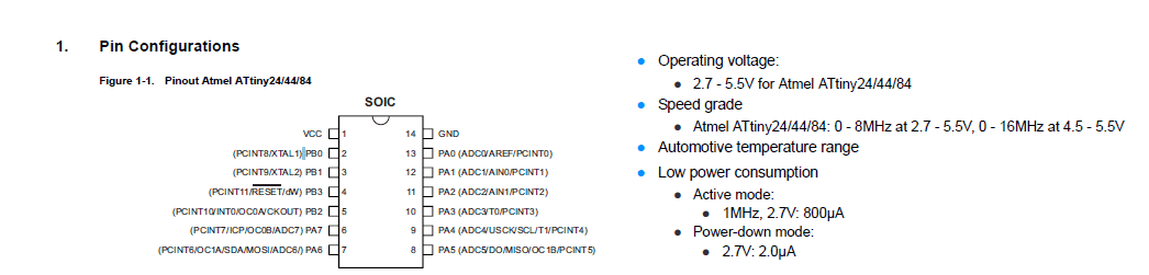
As per the datasheet file pages 56-60 explain the pins.
Pin 1,2,3,4,7,8,9,12,13,14 are default connections.
Pin 5 for is for output.
Pin 6,10,11 are for output an input.
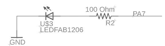
I used Pin 6 (PA7) for the LED (output) and Pin 10 (PA3) for the button (input). The Reset button should be connected to VCC with a resistor 10k (according to the original design) and we should add a Capacitor 10uf(according to the original design) between the VCC and the GND.
LED
According to the LED datasheet we should always use current limiting resistor.
To know which resistor to use we have apply a formula:
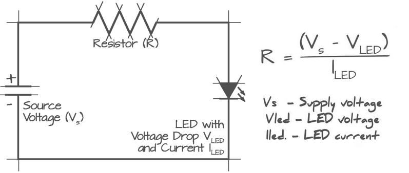
Following the formula and datasheet: 5-2.4/0.03=86.66 Ohm so the resistor we will use is 100 Ohm.
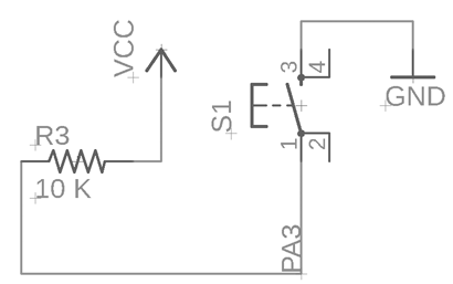
Push Button
The push button should be connected to the GND, Pin 10 (PA3) input, to a resistor 10K and VCC.
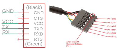
ISP and FTDI
ISP connection is to program the board.

FTDI connection is to link it to the PC serial port.
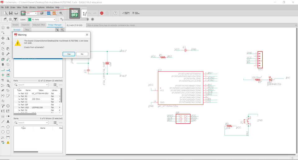
Creating the Board
Generate a board by clicking on SCH/BRD.
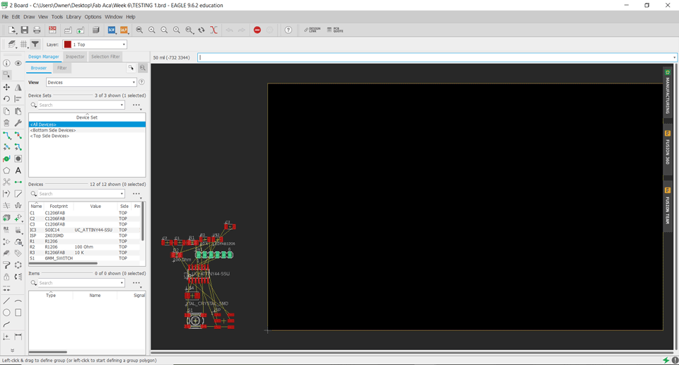
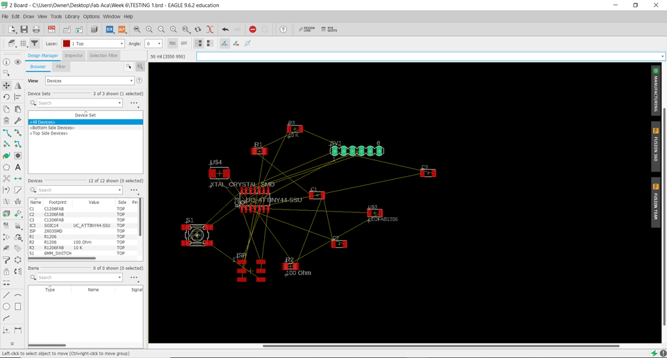
Second step is to place the components.
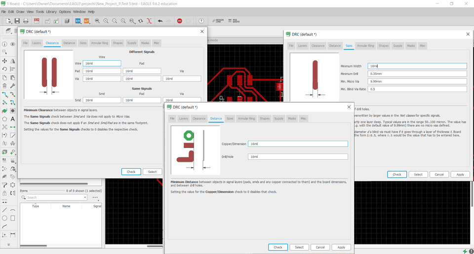
Here it is important to add design rules to the PCB to make sure that the design does not contain errors.
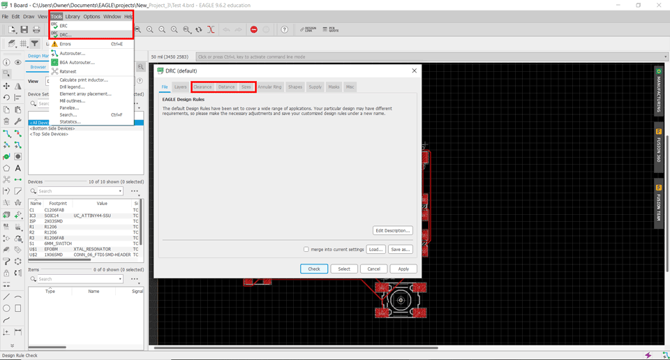
Then we have to adjust the Clearance, Distance, Sizes to 17 mil.
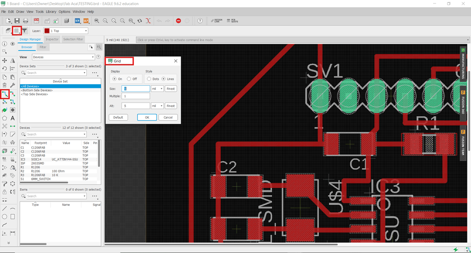
Here we will turn on the Grid and check its settings for more precision.
Using the Route command we will start connecting the components together.
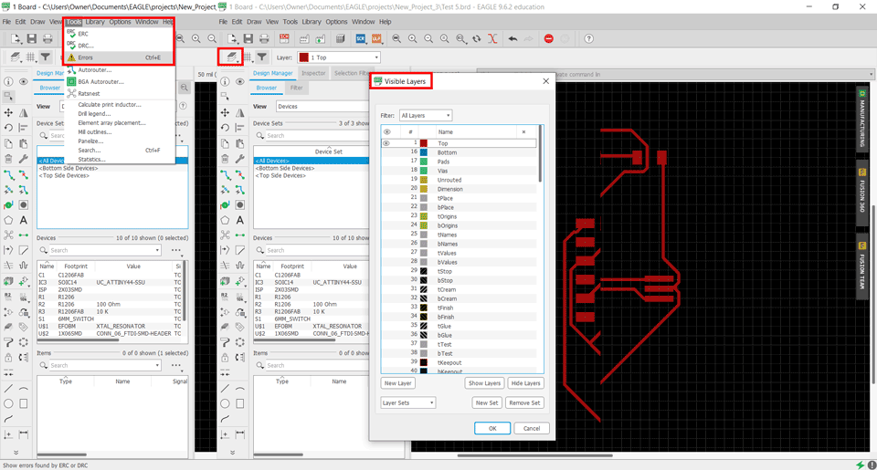
We have to check for errors from the tolls tab and click on errors.
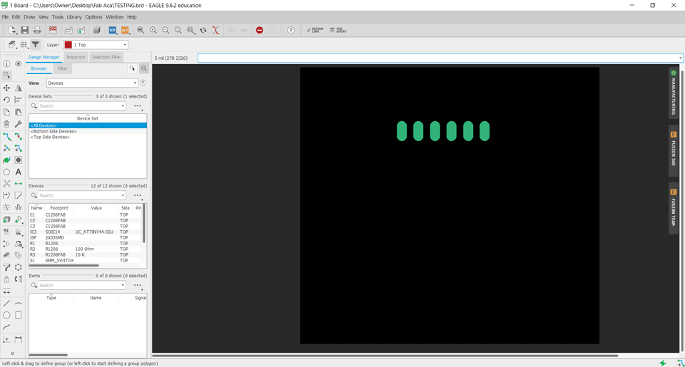
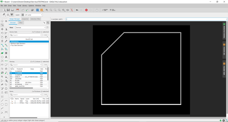
To extract the inner traces we should go to the layers panel and turn off all layers except top.
To extract the outer traces we should go to the layers panel and turn off all layers except outer.
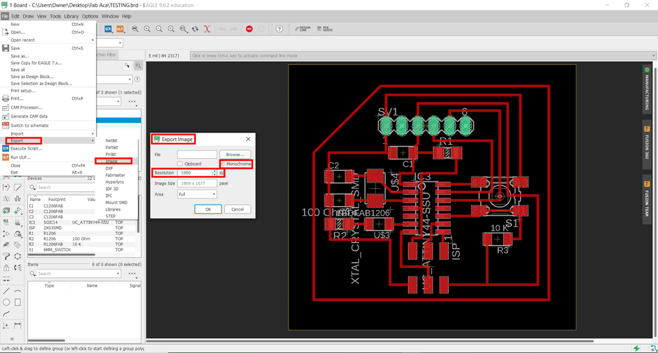
The extracted file image should be png: file-export-image.
The settings should be monochrome with resolution 1000 dpi.
Same steps to extract the outer line of the pcb and the points to be drilled.
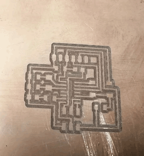
Milling the Board
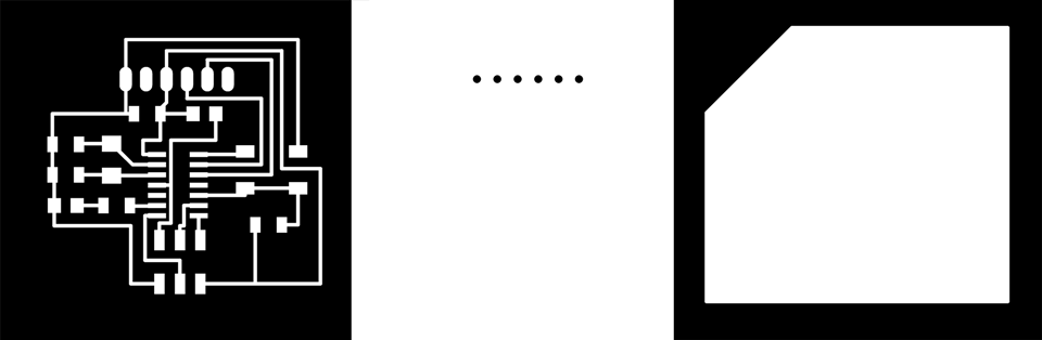
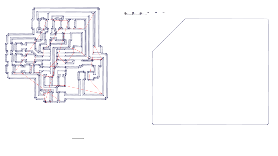
After extracting the inner lines, holes for drilling and the outer traces as png images we have to use Photoshop to invert the colors and create a G-code in order to use the milling machine.
Electronics Production refer to electronics production assignment for more details.
Extracted images and the Gcodes
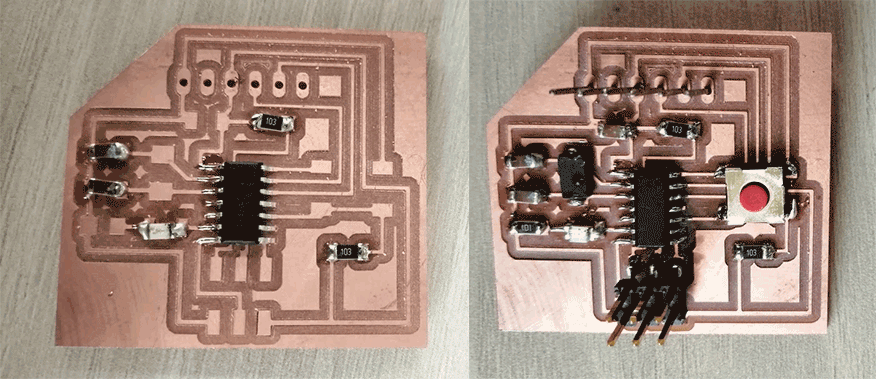
Result
Soldering
For soldering I will insert the values of each component on eagle.
Also I checked the polarities in order to solder the components in the right way.
Software Installation
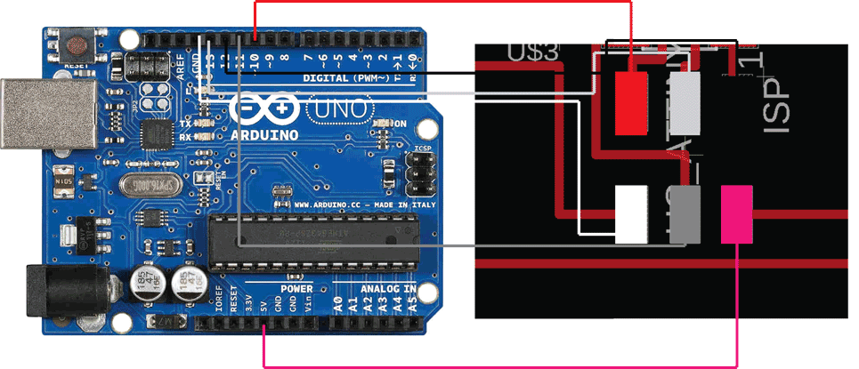
GND on my board to GND on Arduino (white cable)
RST on my board to Pin 10 on Arduino (red cable)
MOSI on my board to Pin 11 on Arduino (dark grey cable)
SKC on my board to Pin 13 on Arduino (light grey cable)
VCC on my board to VCC on Arduino (purple cable)
MISO on my board to Pin 12 on Arduino (black cable)
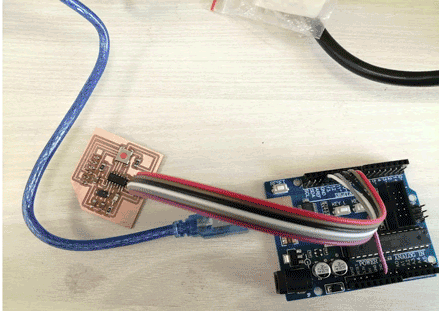
Arduino
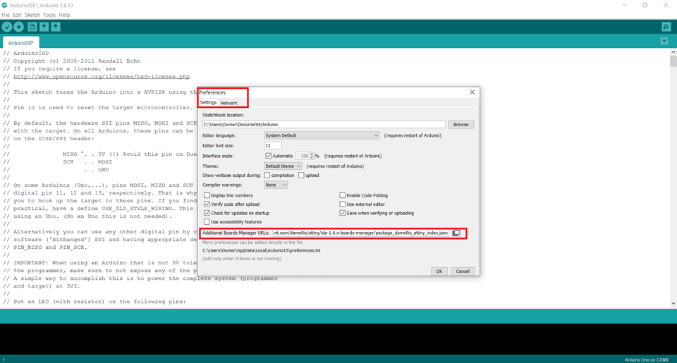
We have to install ATtiny44 board on the Arduino IDE since we are using ATtiny44 microcontroller. For that we go to file-preferences-settings and insert this link: "https://raw.githubusercontent.com/damellis/attiny/ide-1.6.x-boards-manager/package_damellis_attiny_index.json"
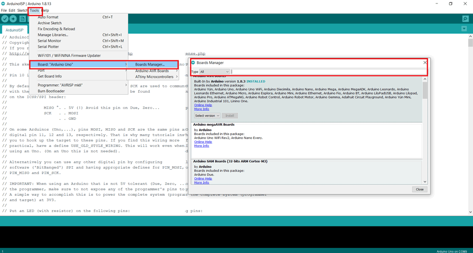
In the tools tab choose board-board manager and install the ATtiny program.
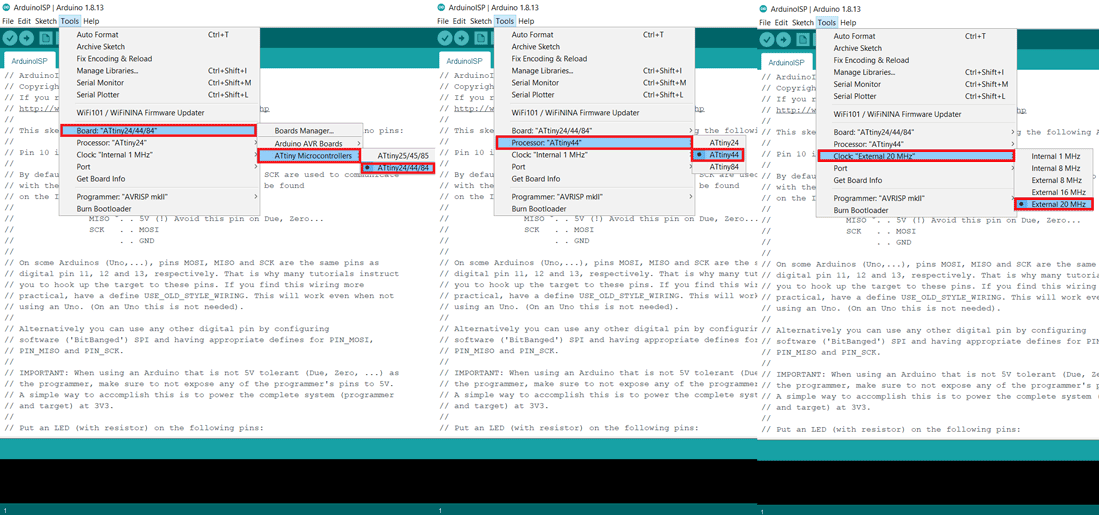
After installing the ATtiny program in the tools tab:
Programmer should be set to Arduino as ISP
Set the board: ATtiny microcontrollers: ATtiny 24/44/84
Processor: ATtiny44
Clock: External 20 MHz
Finally tools: burn bootloader to program the board for the first time.
Programing and Uploading the code
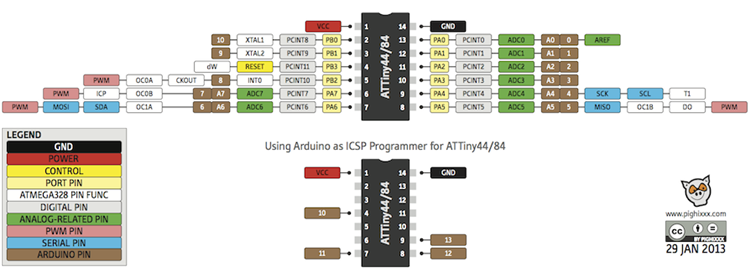
Using this chart I used Arduino pin numbers in the coding following my eagle schematic:
Pin 6 (PA7) is for Red LED in my board and will be Pin 7 on Arduino.
Pin 10 9PA3) is for Push Button in my board and will be Pin 3 on Arduino.
This is the arduino code for the button.
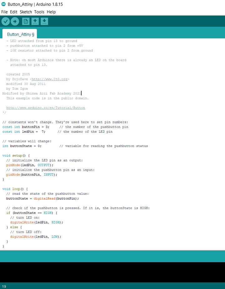
In the above test code I modified the button and LED pins according to my board design.
While uploading the code using arduino an error happened and I couldn't program my board.
I tried to fix the soldering around the microcontroller also I tried to change the wires but it was still not working.
I have to check the microcontroller or maybe replace it with a new one.
I designed a new board in the Embedded Programming Week and tested it using all the previous steps that I mentioned and it worked.
I did the same exercise using this board.
Group Assignment
Here you can find our group assignment LINK
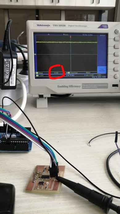
Testing Input Voltage
We connected the Positive Probe of the Tektronix TBS1052B to on the Vcc of the board and the Negative Probe to the Gnd of the board and we read the 5V signal on the screen.
Testing SCK PIN
Here we connected the Positive Probe to the SCK Pin on the board and we read the signal while uploading the code.
Testing Blinking LED
Here we connected the Positive Probe to the LED on the board and we read the signal while the led is blinking: the code used is a simple blink code.

This work is licensed under a Creative Commons Attribution-NonCommercial-ShareAlike 4.0 International License