Group Assignment
- Design a machine that includes mechanism +actuation + automation.
- Build the mechanical parts and operate it manually.
- Actuate and automate your machine.
- Document the group project and your individual contribution.
Here you can find our group assignment LINK
Mechanical Design
In this group project first, we searched for the available components in the lab. Rods, stepper motors, servo motors, linear motion bearings, screws …
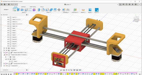
The rods we found were L = 40 cm and Diameter = 8 mm so we decided to do a 2 axes CNC pen plotter that will be limited to the dimensions of the rods in which it can draw up to an A3 size.
The different parts of the project:
- Main Body 1 the X axis
- Main Body 2 the Y axis
- The pen holder the Z axis
The components used:
- Two stepper motors
- One servo motor
- Four linear bearings for 8 mm shafts
- 8 mm threaded rod
- Two 8 mm rods
- Two stepper motor belts
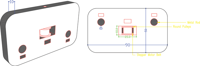
The Main Body Dimensions and Design
Part One:
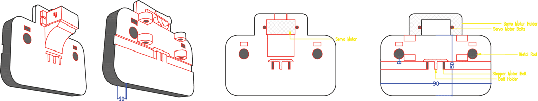
Part Two: Servo Motor Holder
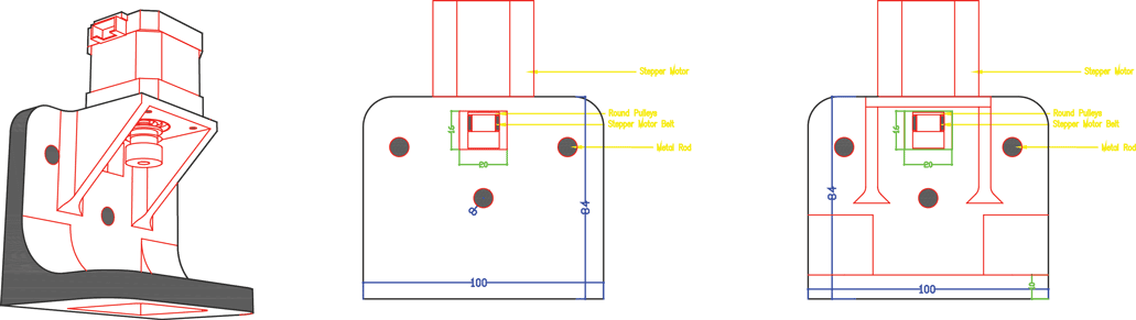
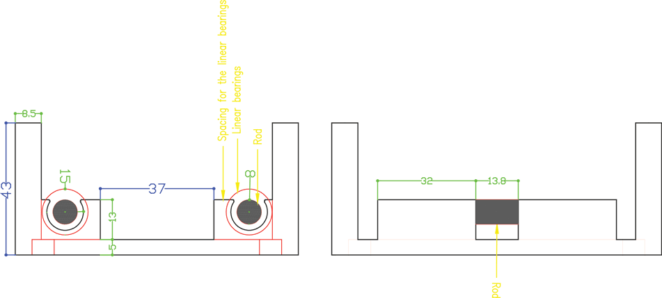
Part Three: Stepper Motor Holder
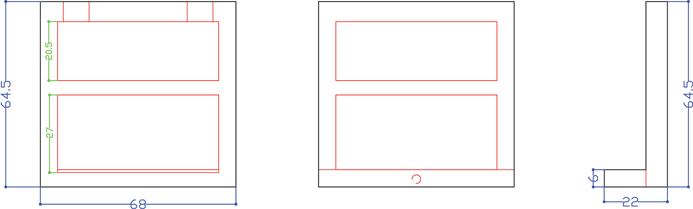
Part Four: Top Holder

Part Five: Bottom Holder
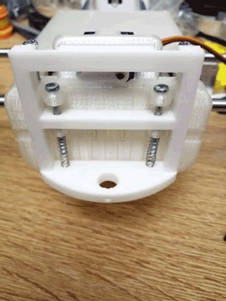
Part Six: Pen Holder
Design Phases
Phase One:
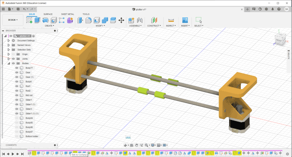
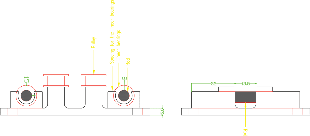
We started by drawing the first phase of the project part two the servo motor holder and part one parallel to it. Taking into consideration the fixed measurements of the components 8 mm rods that will be fixed perpendicularly to the parts, servo motor, pulleys, and stepper motor belt.
Phase Two:
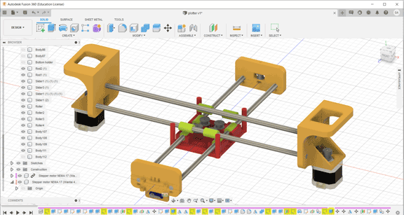
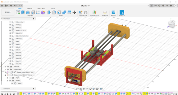
Then in phase two we measured the stepper motors and started designing part three to hold the motors taking into consideration the pulleys and the belt movement. The stepper motor holder is designed with an opening inside it a rectangle 18 x 16 mm that will include the pulley and the belt taking into consideration its movement without having friction. We also did a 45° support to hold the motor without breaking.
Phase Three:
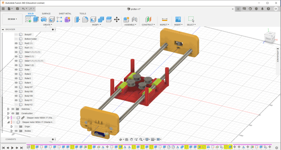
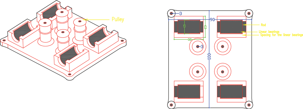
Phase three we designed the box holder that will include the linear bearings with 8 mm shafts so that the rods will pass inside it and the holder will move in two axes x and y. We measured the bearings 15 mm outer diameter and 8 mm inner diameter for the rods with a length of 24 mm. To hold the bearings, we drew the outer diameter and did an offset with a smaller diameter 12 mm so that the bearing can sit inside the holder without falling. The upper bearing will be perpendicular to the lower part allowing the machine to move along the metal rods in the two axes freely. We designed the bottom holder part five taking into consideration the four pulleys that will guide the stepper motor belt.
Phase Four:
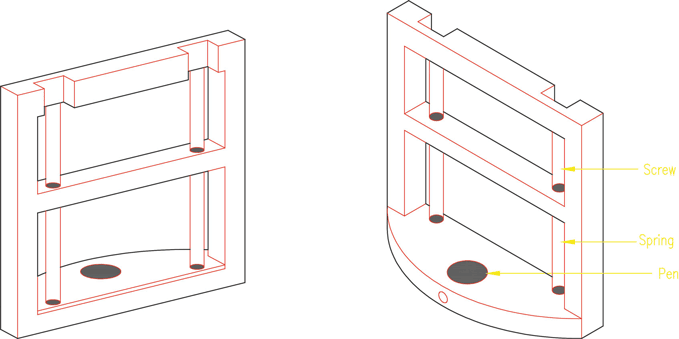
The pen holder will be fixed to the servo motor with screws allowing it to turn and raise it in the z axis up and own. It will include a pen and springs to move and draw whatever is sent to it.
Preparing the files for 3D Printing
In the Fusion 360 file we have to save each part alone as. stl to prepare it for 3d printing.
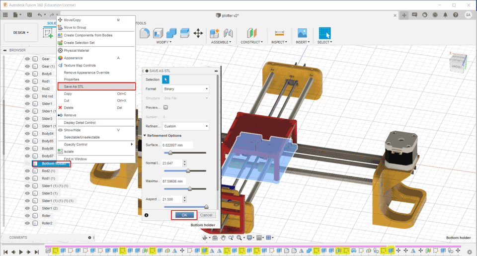
In total we have seven parts for 3d printing.
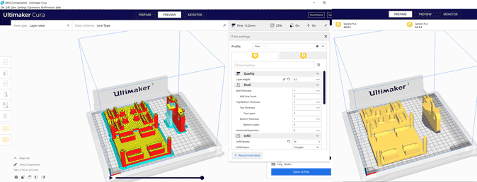
I prepared the files for printing with recommended setting on Cura.
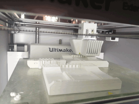
In the first printing trial I used two 3D printers Delta WASP2040 and Ultimaker 3 Extended.
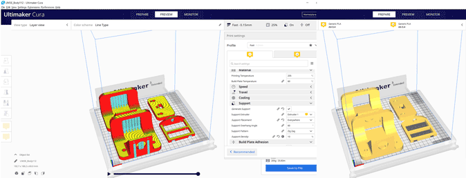
In the second printing we used Ultimaker 3 and another Ultimaker 3 Extended.
Ultimaker Cura slicer to prepare the Gcodes.
The settings for both trials are:
Layer height 0.2 mm
Infill 25%
Support everywhere
First Printing Trial
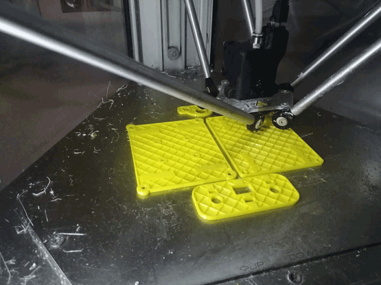
Second Printing Trial
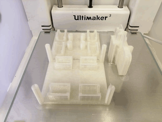
Assembly Trial One:
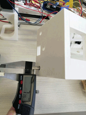
In the first printing we faced a lot of problems related to the measurements. The printers were not accurate enough.
For the rods in the Ultimaker the circle for the rod was very small 7.3 mm instead of 8 mm and it did not fit inside the print.
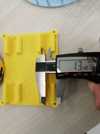
Also, the space for the linear bearings was small and they did not fit easily in the top and bottom holders. Diameter should be 15 mm after printing it was 13.4 mm.
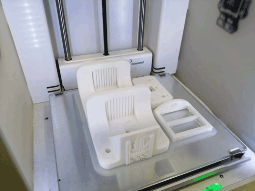
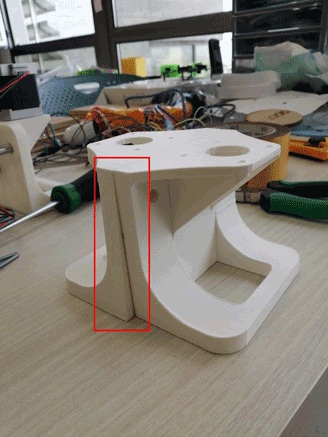
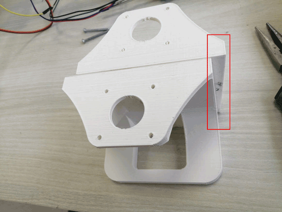
In the Ultimaker printer we had a problem in the calibration x and y axes. After finishing the prints, they were not straight and distorted. So, the machine cannot be assembled.
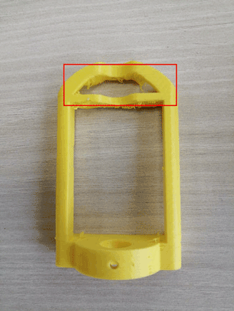
Then while checking the pen holder we discovered that we did not give the servo motor enough space to rotate and move the part.
After checking all these problems, we went back to the fusion file and did some edits in the file design and measurements.
Assembly Trial Two:
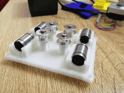
First, we assembled the bottom holder inserted the linear motion bearings with the pulleys.
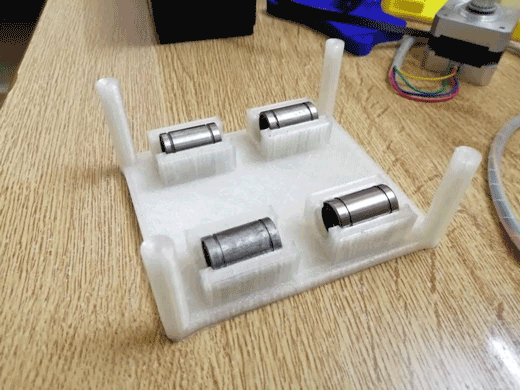
Then the top holder also inserted the linear motion bearings.
In the next step we placed rods, stepper motor holder and the stepper motors from the first axis and the other rods and servo motor parts for the second axis.
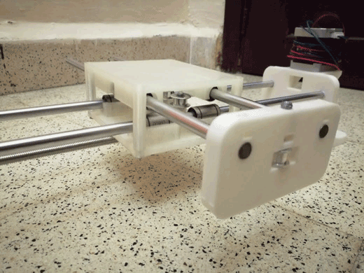
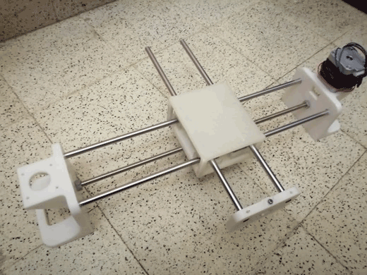
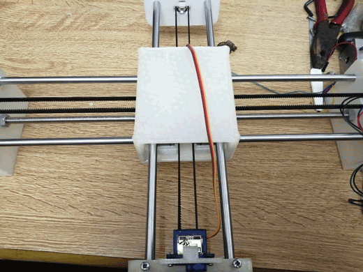
After assembling these parts, the machine can be moved by hand.
Machine Design
Our CNC pen plotter machine has 2 axes with 2 stepper motors, the x and y axes have limitations in length because they are on rods limited to 40cm.
The pen is controlled by a servo motor. The servo motor is connected to the pen holder with springs and a pen inserted inside it that lift it up and down.
In the first trial to automate the machine I followed the bellow steps:
I used a grbl-Servo library to control the Arduino and the motors.
Then I connected the Arduino to a Gcodes sender. In our case I used Source Rabbit gcode sender.
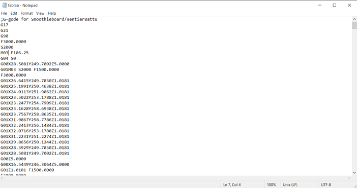
Then I had to modify some settings to match our machine gears and wheels dimensions. The gcode was generated in fabmodules and I had to modify it in notepad in order to adjust some settings to work with the grbl-Servo we used.
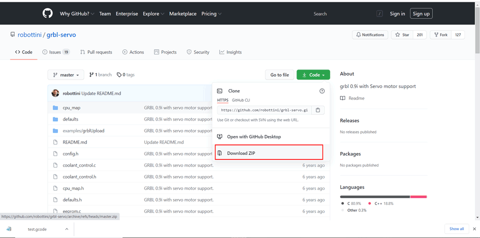
Step One: Download and Install GRBL
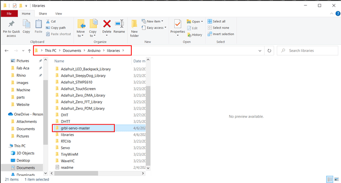
First, I downloaded the grbl library and add to the Arduino IDE libraries folder.
I used the grbl-servo library since we have a servo motor, and we have to control it in our machine using the Gcode.
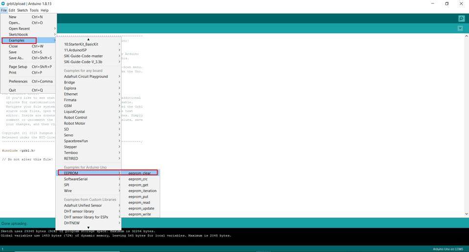
Then in Arduino I had to click on File tab – Examples – EEPROM – eeprom_clear
I did this step to erase the chip and reprogram it.
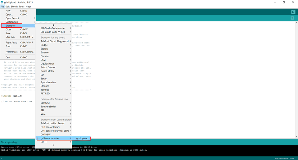
Now I will upload the grbl from the examples folder in Arduino.
File tab – Examples – grbl-servo-master – grblUpload
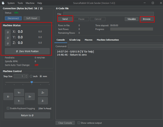
Step Two: Installing the Gcode sender
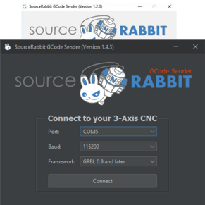
Download SourceRabbit gcode sender and install it.
Then I need connected it to port COM3 and Baud 115200 to match the connected Arduino port.
Once we are connected, we need to change some settings. The grb; settings should be related to our machine gears and dimensions.
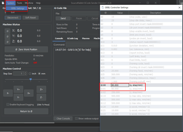
X-axis resolution = 80 step/min
Y-axis resolution = 80 step/min
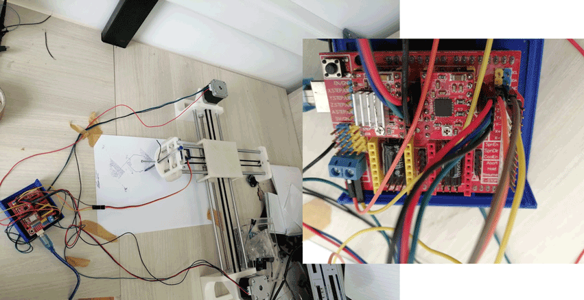
Step Three: Arduino and CNC Shield
The shield itself consists of the big red board with smaller red boards that are used to control motors. The smaller boards are called the motor driver boards and correspond to the X-, Y-, and Z-axes.
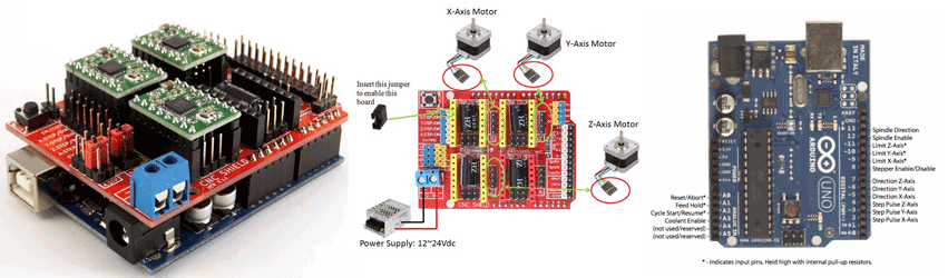
We will plug a Stepper motor driver A4988 and place jumpers for micro stepping.
Then we will connect the 2 stepper motors that are for the X and Y axis and the servo motor on pin 11.
Step Four: Preparing the Gcode
I used fabmodules to generate the firsttrial gcode.
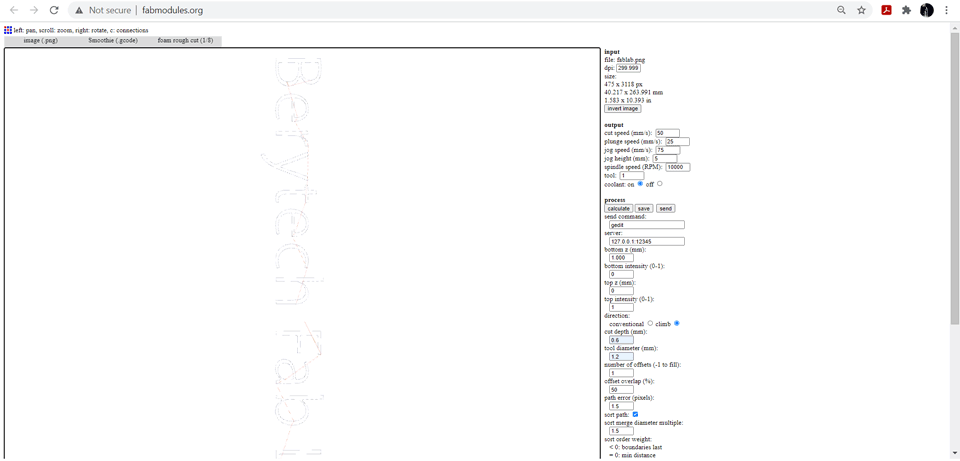
After generating the Gcode I modified it using notepad in order to control the servo motor.
Z5.000 will be replaced by M03 S000 to start the servo and rotate CW.
Z 1.0181 will be replaced by M03 S2000 to rotate the servo down and start the machine.
Step Five: Sending the Gcode
Make sure the machine board is connected to Source Rabbit Gcode Sender then click on browse and select the modified Gcode then click send. Before sending the file, I had to make sure of our work position 0,0,0.
Step Six: Testing the Machine
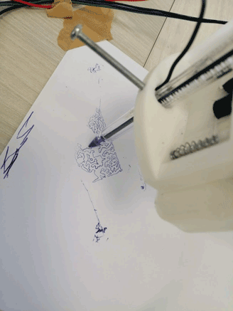
Videos Trials:
Final Result
As a result my contribution in this project was prepring the first files for 3D printing, printing them and trying to assemble. Then I worked on the first automation trial I downloaded the needed softwares connected the machine and tried it.

This work is licensed under a Creative Commons Attribution-NonCommercial-ShareAlike 4.0 International License