Group Assignment
Probe an input device's analog levels and digital signals
Individual Assignment
Measure something: add a sensor to a microcontroller board that you have designed and read it.
Individual Assignment
Input Devices
Any of many hardware devices that generate and/or interface input (from a user or elsewhere) to a computer. Data input devices can be used to insert data into a computer or other computational devices.
In this assignment I test and check some of the sensors that I will use in my final project.
For the tests I will use the Arduino Board since it has the same microcontroller ATmega328P that I will be using in my final project.
The sensors that I will be using are the below:
- LED
- Humidity and Temperature Sensor DHT22
- Soil Moisture Sensor
- Water Level Sensor
- LDR Sensor
- Ultrasonic sensor
For all the sensors I watched tutorials and checked datasheets in order to know how to connect and read data of each sensor.
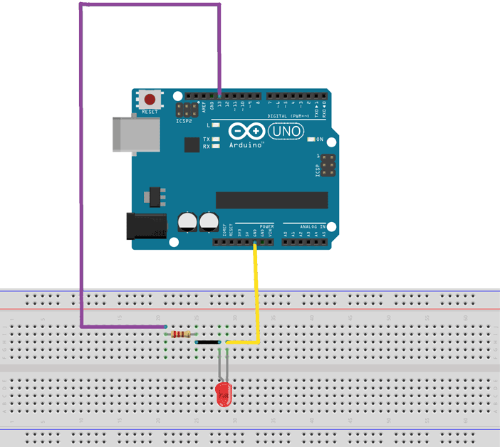
LED
Diagram
Code
                            /*
  Blink

  Turns an LED on for one second, then off for one second, repeatedly.

  Most Arduinos have an on-board LED you can control. On the UNO, MEGA and ZERO
  it is attached to digital pin 13, on MKR1000 on pin 6. LED_BUILTIN is set to
  the correct LED pin independent of which board is used.
  If you want to know what pin the on-board LED is connected to on your Arduino
  model, check the Technical Specs of your board at:
  https://www.arduino.cc/en/Main/Products

  modified 8 May 2014
  by Scott Fitzgerald
  modified 2 Sep 2016
  by Arturo Guadalupi
  modified 8 Sep 2016
  by Colby Newman

  This example code is in the public domain.

  https://www.arduino.cc/en/Tutorial/BuiltInExamples/Blink
*/

// the setup function runs once when you press reset or power the board
void setup() {
  // initialize digital pin LED_BUILTIN as an output.
  pinMode(LED_BUILTIN, OUTPUT);
}

// the loop function runs over and over again forever
void loop() {
  digitalWrite(LED_BUILTIN, HIGH);   // turn the LED on (HIGH is the voltage level)
  delay(1000);                       // wait for a second
  digitalWrite(LED_BUILTIN, LOW);    // turn the LED off by making the voltage LOW
  delay(1000);                       // wait for a second
}
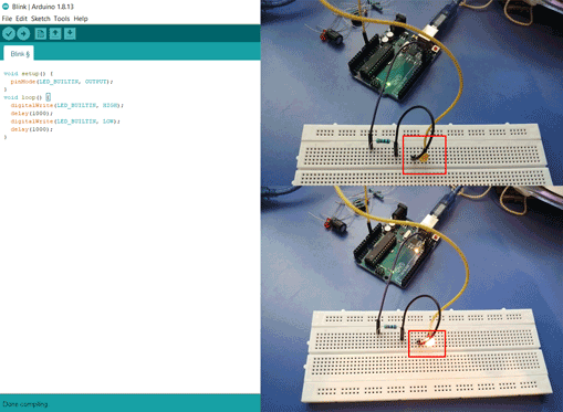
Explanation
In the above code the LED will blink on and off with a delay of one second.
Humidity and Temperature Sensor DHT22
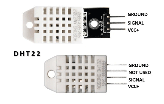
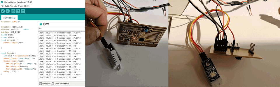
DHT-22 is a digital-output humidity and temperature sensor. It is a capacitive proximity humidity sensor and a thermometer to measure the surrounding air, and gives out a digital signal on the data pin.
From the above description of the sensor I noticed that it needs only one digital input to measure the measure the values.
Diagram

Code
Here for the code I had to download the library in order for the sensor to start measuring the humidity and temperature.
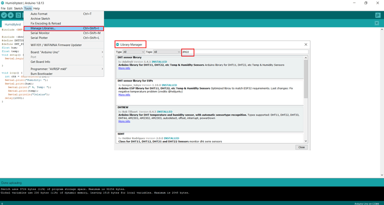
Click on tools - manage libraries - library manager then search for the needed library.
Code
Written by Arduino
Modified by Ghinwa Azzi Fab Academy 2021
#include DHT.h

#include dhtnew.h
#define DHTTYPE    DHT22
#define DHT_PIN2
float hum;
float temp;
void setup() {
  Serial.begin(9600);

}

void loop() {
  int chk = digitalRead(PIN2);
  Serial.print("Humidity: ");
  Serial.print(hum);
    Serial.print(" %, Temp: ");
    Serial.print(temp);
    Serial.println("Celsius");
  delay(1000);
}
The original code is from the main arduino page and I modified it for the purpose of Fab Academy 2021 input devices exercise. I changed the library according to the one I have in my libraries folder, also I changed the pin number of the sensor with the delay time between the readings.
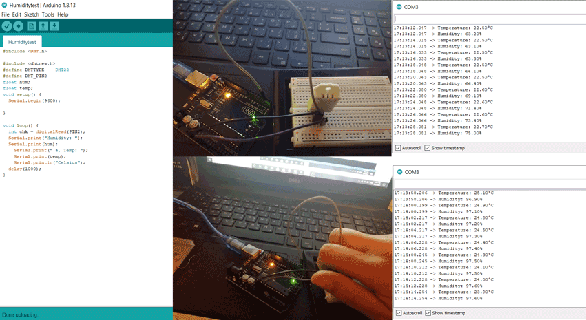
Explanation
In the above code PIN2 is the digital data pin that is reading the changing humidity and temperature. I did two tests in the second I covered the sensor and we can see changing humidity values on the arduino serial monitor.
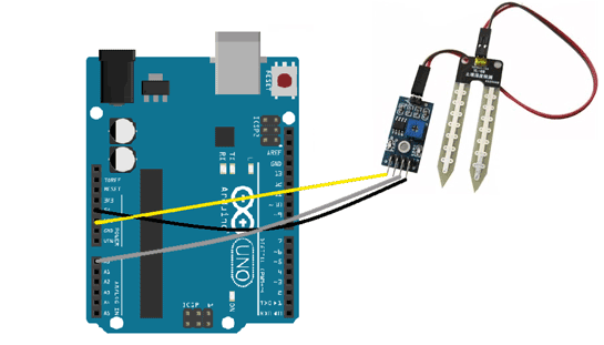
Soil Moisture sensor
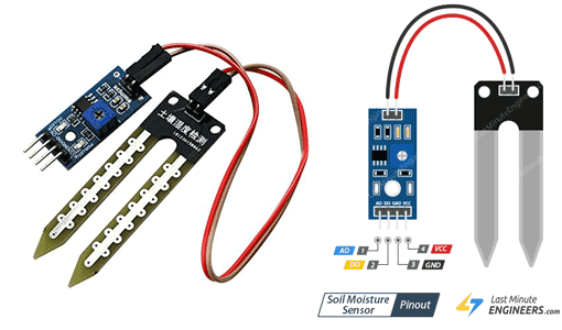
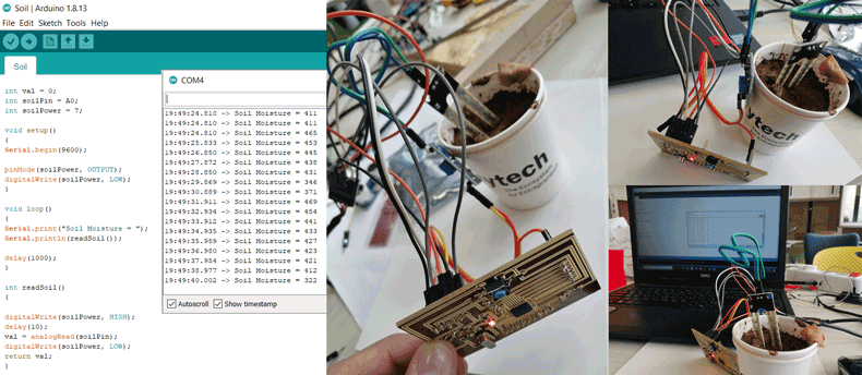
The soil moisture sensor consists of two probes that are used to measure the volumetric content of water. The two probes allow the current to pass through the soil, which gives the resistance value to measure the moisture value.
From the above description of the sensor I noticed that it can be connected in analog and digital modes. In my test I connected it to the analog mode.
Diagram
Code
Also here for the code I had to download the library in order for the sensor to start measuring the soil moisture level.
Same steps as mentioned previously:
Click on tools - manage libraries - library manager then search for the needed library.
Code
Written by lastminuteengineer
Modified by Ghinwa Azzi Fab Academy 2021
int val = 0;
int soilPin = A0;
int soilPower = 7;

void setup()
{
Serial.begin(9600);

pinMode(soilPower, OUTPUT);
digitalWrite(soilPower, LOW);
}

void loop()
{
Serial.print("Soil Moisture = ");
Serial.println(readSoil());

delay(1000);
}

int readSoil()
{

digitalWrite(soilPower, HIGH);
delay(10);
val = analogRead(soilPin);
digitalWrite(soilPower, LOW);
return val;
}
The main code is from an online webpage (last minute engineer) and I modified it for the purpose of Fab Academy 2021 by changing the readings that will appear on the arduino serial monitor and the sensor readings delay time.
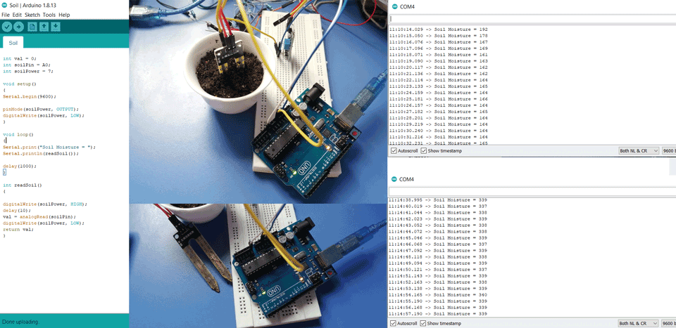
Explanation
In the above code PINA0 is the analog input that is reading the soil moisture level. I did two tests in the first I inserted the sensor in the soil and in the second I removed the sensor from the soil and we can see the results on the arduino serial monitor.
Also, while reading the datasheet of the sensor one commonly known issue is their short lifespan when exposed to a moist environment and corrosion. A solution for this is to power it only when you take the readings and not constantly. So in this case we will need to connect it to a digital pin and in the above code it is PIN7.
Water Level sensor
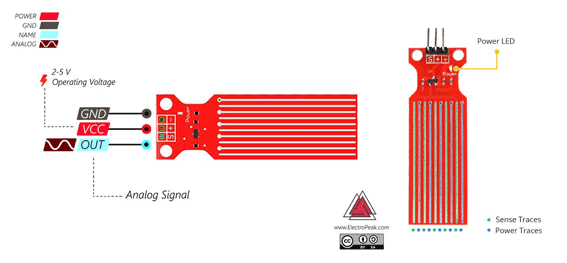
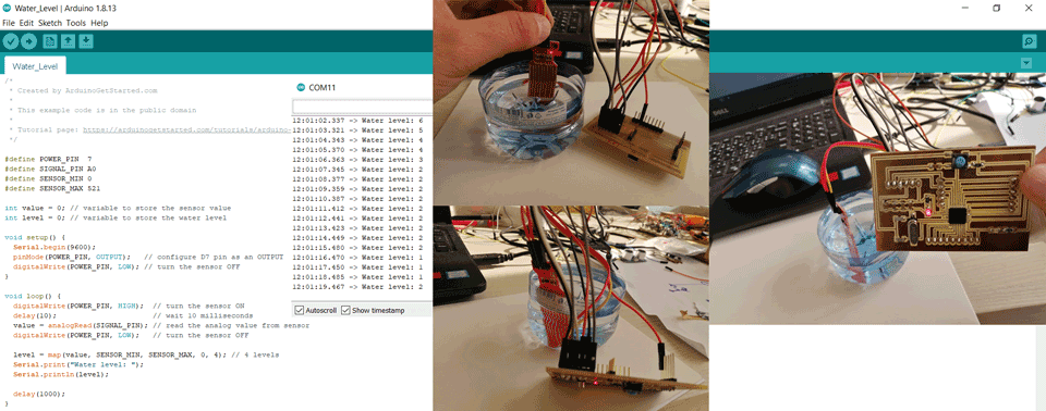
The series of the sense and power exposed to water are parallel conductors, together acts as a variable resistors in which thy give the reading according to the water level.
From the above description of the sensor I noticed that it can be connected in analog and digital modes. It has three pins the signal pin in my test I connected it to the analog mode.
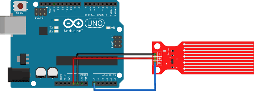
Diagram
Code
Also here for the code I had to download the library in order for the sensor to start measuring the soil moisture level.
Same steps as mentioned previously:
Click on tools - manage libraries - library manager then search for the needed library.
Code
Written by Arduino
Modified by Ghinwa Azzi Fab Academy 2021
// Sensor pins
#define sensorPower 5
#define sensorPin A2

// Value for storing water level
int val = 0;

void setup() {
  // Set D5 as an OUTPUT
  pinMode(sensorPower, OUTPUT);

  // Set to LOW so no power flows through the sensor
  digitalWrite(sensorPower, LOW);

  Serial.begin(9600);
}

void loop() {
  //get the reading from the function below and print it
  int level = readSensor();

  Serial.print("Water: ");
  Serial.println(level);

  delay(1000);
}

//This is a function used to get the reading
int readSensor() {
  digitalWrite(sensorPower, HIGH);  // Turn the sensor ON
  delay(10);              // wait 10 milliseconds
  val = analogRead(sensorPin);    // Read the analog value form sensor
  digitalWrite(sensorPower, LOW);   // Turn the sensor OFF
  return val;             // send current reading
}
The main code is from an online webpage (last minute engineer) and I modified it for the purpose of Fab Academy 2021 by changing the readings that will appear on the arduino serial monitor and the sensor pins with the readings delay time.
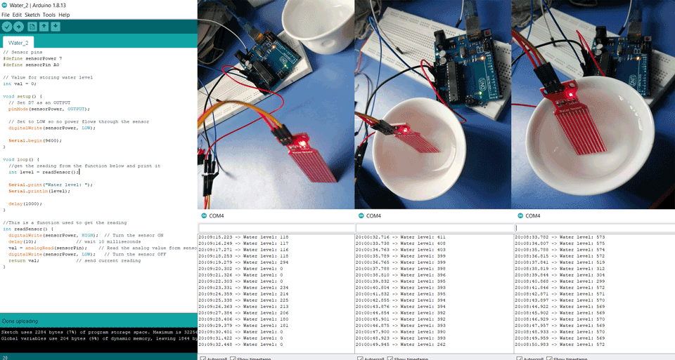
Explanation
In the above code PINA0 is the analog input that is reading the water level. I did three tests in the first I the sensor was not in the water and as we can see in the test the reading was 0. In the second I the sensor was put in a low water level and we can see the results ranging from 200 to 400 and in the third test the sensor was fully submerged and we can see the results on the arduino serial monitor.
Also, while reading the datasheet of the sensor one commonly known issue is their short lifespan when exposed to a moist environment and corrosion. A solution for this is to power it only when you take the readings and not constantly. So in this case we will need to connect it to a digital pin and in the above code it is PIN7.
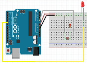
LDR Sensor
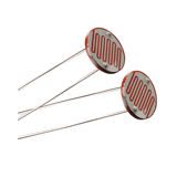
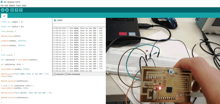
Photoresistors, also known as light dependent resistors (LDR), are light sensitive devices most often used to indicate the presence or absence of light, or to measure the light intensity.
LDRs have a sensitivity that varies with the wavelength of the light applied on it.
From the above description of the sensor I noticed that it is connected to the analog pin modes. It has two pins the signal pin and the analog pin.
Diagram
Code
Also here for the code I had to download the library in order for the sensor to start measuring the soil moisture level.
Same steps as mentioned previously:
Click on tools - manage libraries - library manager then search for the needed library.
Code
By Ghinwa Azzi Fab Academy 2021

const int ledPin = 9;

const int ldrPin = A0;

void setup() {

Serial.begin(9600);

pinMode(ledPin, OUTPUT);

pinMode(ldrPin, INPUT);

}

void loop() {

int ldrStatus = analogRead(ldrPin);

if (ldrStatus >200) {

digitalWrite(ledPin, HIGH);

Serial.print("Its DARK, Turn on the LED : ");
delay(700);

Serial.println(ldrStatus);

} else { if (ldrStatus <200); }

digitalWrite(ledPin, LOW);

Serial.print(Its BRIGHT, Turn off the LED);

Serial.println(ldrStatus);

}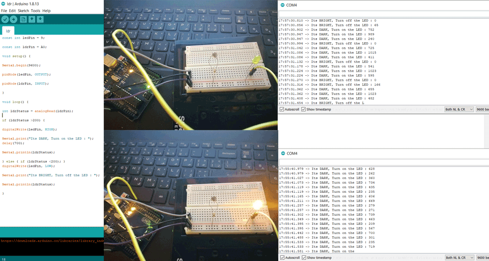
Explanation
In the above code PINA0 is the analog input that is reading the intensity of the light. For the LED it is connected to digital PIN9. I did two tests in the first I the light intensity was hight <200 the LED remained off showing a message: Its BRIGHT, Turn off the LED. In the second test the light intensity was low >200 the LED turned on showing a message: Its DARK, Turn on the LED.
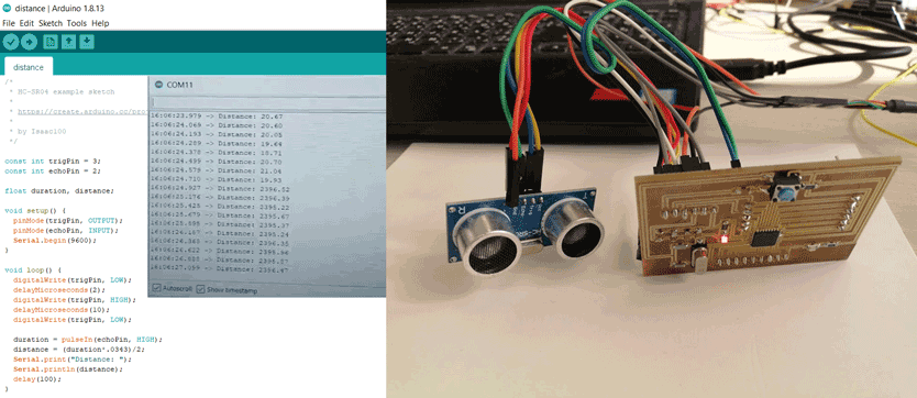
HC-SR04 Ultrasonic Sensor
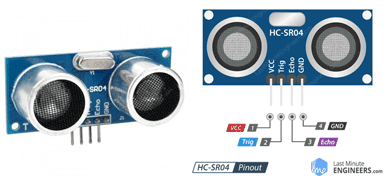
Ultrasonic Distance Sensor that can report the range of objects up to 13 feet or 400 cm away. Ultrasonic distance sensor consists of two ultrasonic transducers, in which one acts as a transmitter which converts electrical signal into ultrasonic sound pulses.Then it produces an output pulse whose width can be used to determine the distance the pulse travelled.
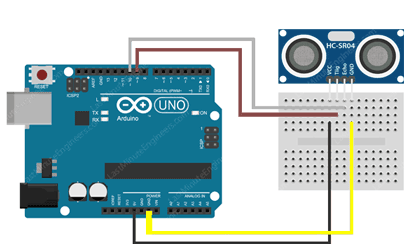
Detection range between 2 cm to 400 cm. From the above description of the sensor I noticed that it is connected to the digital mode. It has four pins the trigger, echo, vcc and ground.
Diagram
Code
Also here for the code I had to download the library in order for the sensor to start measuring the soil moisture level.
Same steps as mentioned previously:
Click on tools - manage libraries - library manager then search for the needed library.
Code
By Ghinwa Azzi Fab Academy 2021

const int trigPin = 3;
const int echoPin = 2;

float duration, distance;

void setup() {
  pinMode(trigPin, OUTPUT);
  pinMode(echoPin, INPUT);
  Serial.begin(9600);
}

void loop() {
  digitalWrite(trigPin, LOW);
  delayMicroseconds(2);
  digitalWrite(trigPin, HIGH);
  delayMicroseconds(10);
  digitalWrite(trigPin, LOW);

  duration = pulseIn(echoPin, HIGH);
  distance = (duration*.0343)/2;
  Serial.print("Distance: ");
  Serial.println(distance);
  delay(100);
}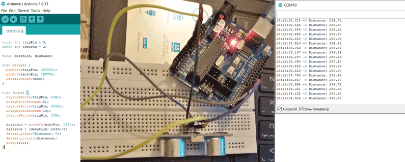
Explanation
In the above code PIN3 is the digital input that is used to trigger the ultrasonic sound pulses ans PIN2 is the digital input that is used to produce a pulse when the reflected signal is received. On the arduino serial monitor we can see the different distances being recorded.
Board Design
I used satshakit as a reference to design my board. Satshakit
ATMega328P Microcontroller
After checking the datasheet I concluded the below:
It is a high performance, low power AVR 8-bit microcontroller.
Pins of ATMega328P
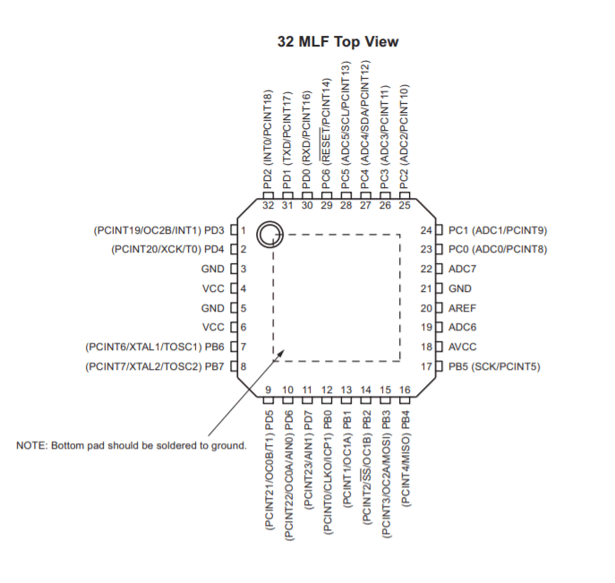
Descriptions:
VCC: Digital supply voltage.
GND: Ground.
Port B: XTAL1 and XTAL2
Port B is an 8-bit bi-directional I/O port. As inputs, port B pins that are externally pulled low will source current if the pull-up resistors are activated. The Port B pins are tri-stated when a reset condition becomes active, even if the clock is not running.
Port C: is a 7-bit bi-directional I/O port. As inputs, Port C pins that are externally pulled low will source current if the pull-up resistors are activated. The port C pins are tri-stated when a reset condition becomes active, even if the clock is not running.
PC6: reset pin, PC6 is used as an input pin.
Port D: Port D is an 8-bit bi-directional I/O port. As inputs, port D pins that are externally pulled low will source current if the pull-up resistors are activated. The port D pins are tri-stated when a reset condition becomes active, even if the clock is not running.
AVCC: AVCC is the supply voltage pin for the A/D converter, PC3:0, and ADC7:6. It should be externally connected to VCC, even if the ADC is not used. If the ADC is used, it should be connected to VCC through a low-pass filter. Note that PC6..4 use digital supply voltage, VCC.
AREF: AREF is the analog reference pin for the A/D converter.
ADC7: ADC7:6 serve as analog inputs to the A/D converter. These pins are powered from the analog supply and serve as 10-bit ADC channels.
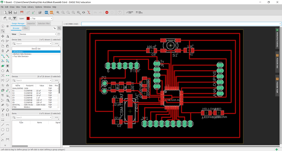
Eagle Board:
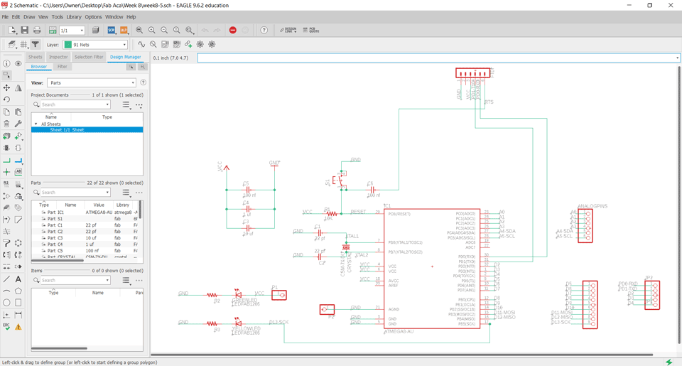
Explanation:
Pin4,6,18: VCC connected to the supply voltage.
Pin7-8: PB6-PB7 XTAL1-XTAL2 are connected to the crystal.
Pin 3-5-21: are connected to the ground.
Pin29: PC6 is connected to the reset.
Pin17: PB5 SCK is connected to the LED.
Pin15: PB3 MOSI digital pin.
Pin16: PB4 MISO digital pin.
Pin30: PD0 is connected to the RXD.
Pin31: PD1 is connected to the TXD.
Pin27: PC4 is analog pin connected to the SDA.
Pin28: PC5 is analog pin connected to the SCL.
A0-A7 are analog pins.
D0-D13 are digital pins.
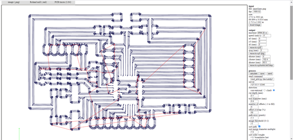
Milling the board:
I used fabmodules to extract the gcodes.
Electronics Production refer to electronics production assignment for more details.
Exported inner traces, the drilling and the cuting image:
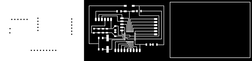
Gcode:
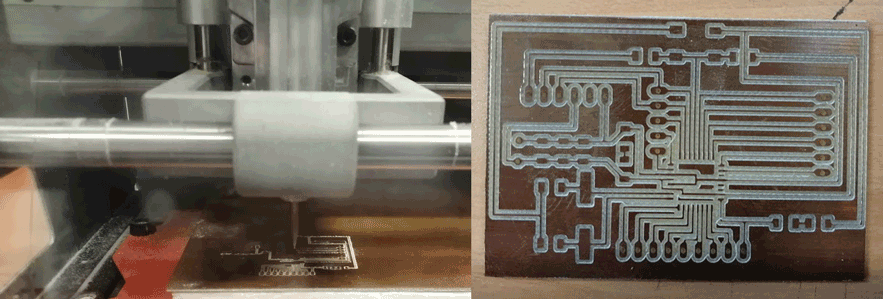
Milling:
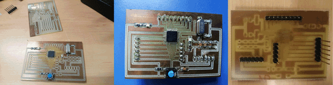
Soldering:
Testing using my board:
Humidity and Temperature Sensor DHT22
Soil Moisture sensor
Water Level sensor
LDR Sensor
HC-SR04 Ultrasonic Sensor
Group Assignment
Here you can find our group assignment LINK
In this group assignment we are going to read an analog input on the Tektronix TBS1052B Digital Oscilloscope.
We used my board that I designed in Embedded Programming week.
Analog Read
We connected an LDR sensor to the board with the positive probe to the LDR and the negative probe to the GND. In the video we can see the values changing on the oscilloscope screen depending on the light intensity.
Digital Read
We connected a push button to the board with the positive probe to the button and the negative probe to the GND. In the video we can see the values changing on the oscilloscope screen when we click the button.

This work is licensed under a Creative Commons Attribution-NonCommercial-ShareAlike 4.0 International License