Ideas and Sketches
Water ReUse Indoor Garden
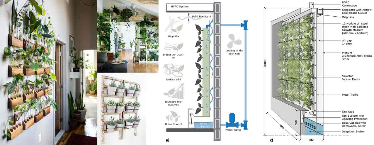
Inspiration Ideas
Main Sketches and Idea:
The project consists of:
Water tanks
Pots that can be assembled in different designs
Main structure to hang the pots on
Humidity and Temperature sensor DHT22
Soil moisture sensor
Photo resistor or LDR sensor
Pipes for watering
The main structure will be made of wood and the pots will be made of PLA plastic.
Project Concept:
Natural and Artificial Lighting:
As my project will be installed on balconies and use natural lighting to grow the plants sometimes we have areas that barely receive light.
So we need artificial lighting in some cases for this I will add lighting that will be controlled through a sensor.
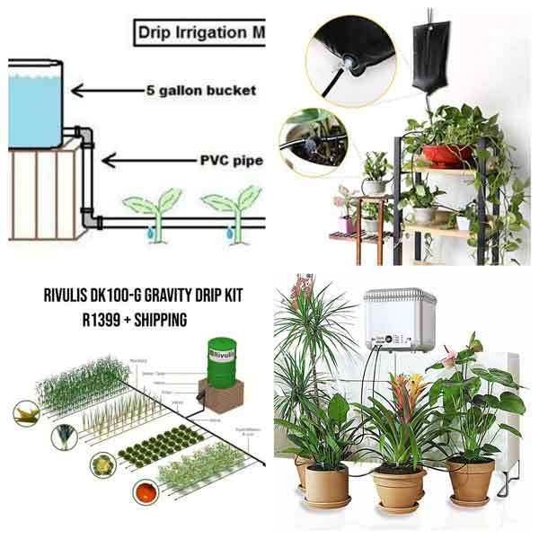
Example of Natural and Artificial lighting in projectsSelf Watering System:
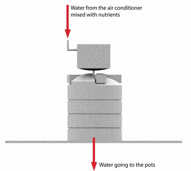
The watering system will be connected to the air conditioners collecting water in a tank from the condensation process. As we know the water will be filtered so in the tank we will need to add nutrients.
From this main tank pipes will be connected to the pots to water the plants through gravity using the self dripping system.
In the tank a solenoid valve will be installed in which it will turn on and off when the tank is full to send the water to the drainage.
The soil humidity sensor will give an order to water the tanks.
One soil humidity sensor will be installed in one pot.
All the sensors including the DHT22 will send the readings to the LCD.
Below are some examples:
Steps to achieve this project:
- Step 1: Research, Design and Drawings
- Step 2: Production process of the main parts of the project.
- Step 3: Preparing the programming phase the board and connecting the sensors.
- Step 4: Combining the parts together the assembly process.
- Step 5: Testing the project to achieve the final result.
Dividing the phases:
At each of the weekly assignments I was planning to do an element that is related to my final project.
Learned skills:
In my final project I will include several skills that I learned during the weekly assignmets.
In the main body or structure of the project I used the Computer Controlled Machining Assignment and skills learned in it.
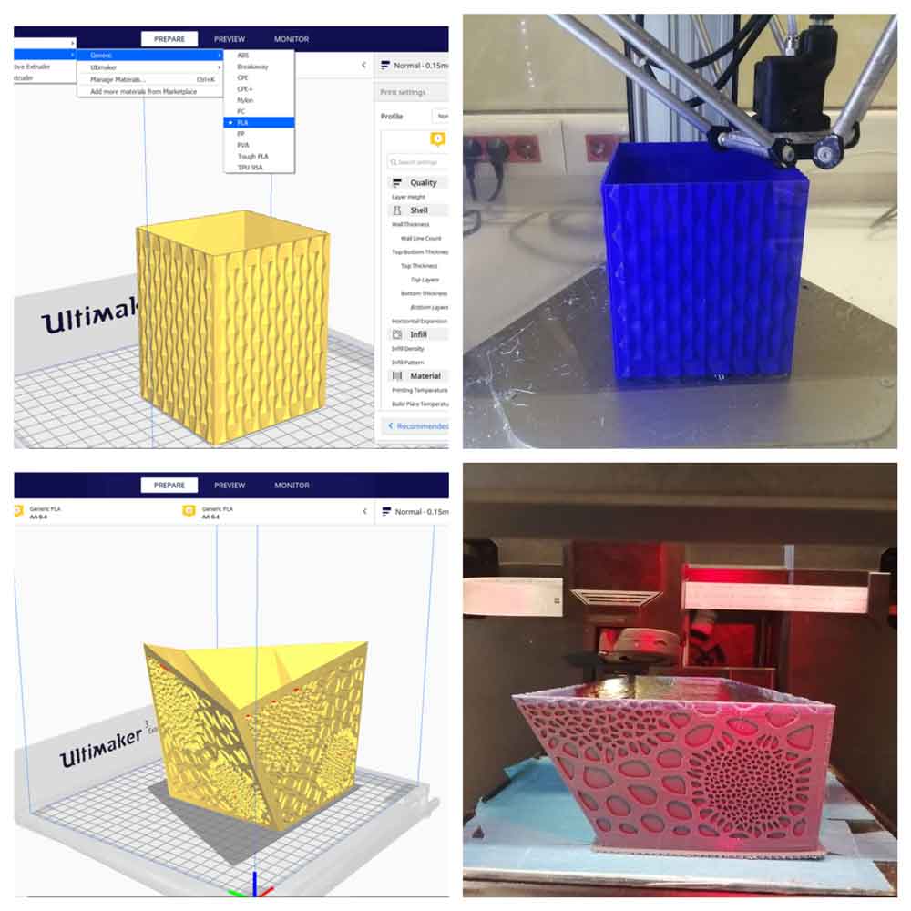
For the pots I used the 3D Scanning and Printing Assignment to 3D print the pots with all the learned skills included.
All the Electronics Assignments and the skills learned for the final PCB.
Programming with the Network and Communication Assignemts also to make the whole project function.
Phase I: Designing the Project
The differents elements of the project with all the details will be explained separately below:
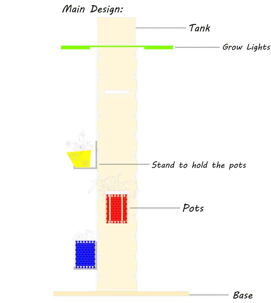
Main structure:
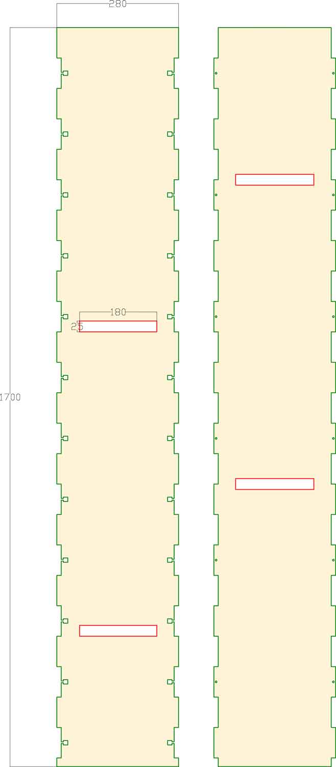
Design with the dimensions:
The design is a simple box that can be assembled easily with screws and bolts to fit any space at our balconies.
The design includes different grooves.
As for the pots in the main structure there are openings to hang the pots in different designs and ditribution according to the space.
I used 10 mm MDF wood for the structure and the whole design is 170 x 28 cm.
 Details about the main structure
Artificial Lighting:
The artificial grow LED light will be supported from above the main body to give light on all the project.
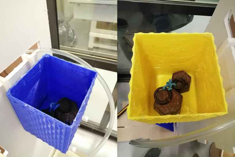
The Pots:
In my project there are two different designs with different colors to make our spaces colorful with the plants.
Each planting pot has its own water supply pipe from the tank.
The tank will be above the main body to save space on our balconies. This tank will have a water supply from the air conditioner with nutrients supplying the pots.
The pipes will be connected and divided in a system to the pots to water for the plants.
Section of the model:
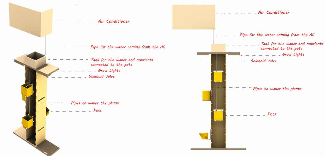
The Automation:
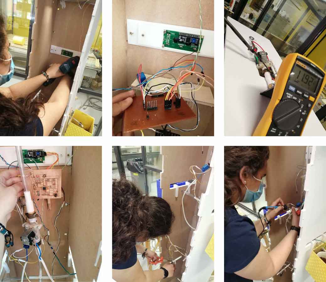
I will place the microcontroller in a box in the middle of the project. It will be easier to reach all the pots from all the sides. All the input and output devices will be placed near the PCB board if possible to reduce the wirings.
As mentioned previously I will use:
Input Devices:
Soil Moisture Sensor
Photo resistor or LDR sensor
DHT22 Humidity and Temperature Sensor
Output Devices:
LCD Screen I2C
Relays
Solenoid Valve
Phase II: Producing the Project
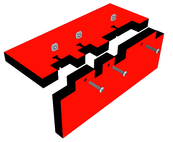
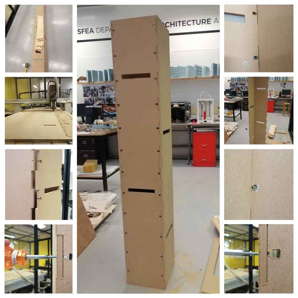
I designed the main structure to be simple and easy to assemble.
I prepared the CNC file to fit in one baord.
The design included:
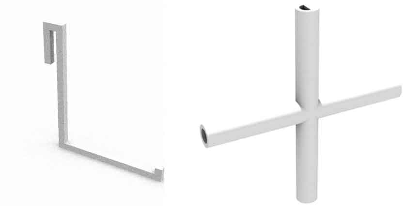
First two sides the dimensions of the openings are rectangles with 7 x 1 cm (thickness of the wood) with 1 mm rounded corners because I will be using the 2 mm router bit.
Second two sides the dimensions of the openings are also rectangles with 7 x 1 cm in addition to a square of 1 cm and a 4 mm rectangle for the screw to connect both parts. I will be using a 4 mm diameter screws.
 Details about the main structure
Here are some shots of the structure production:
The Pots:
The planting pots have patterns that can only be done using 3D printing.
Details about the Planting Pots
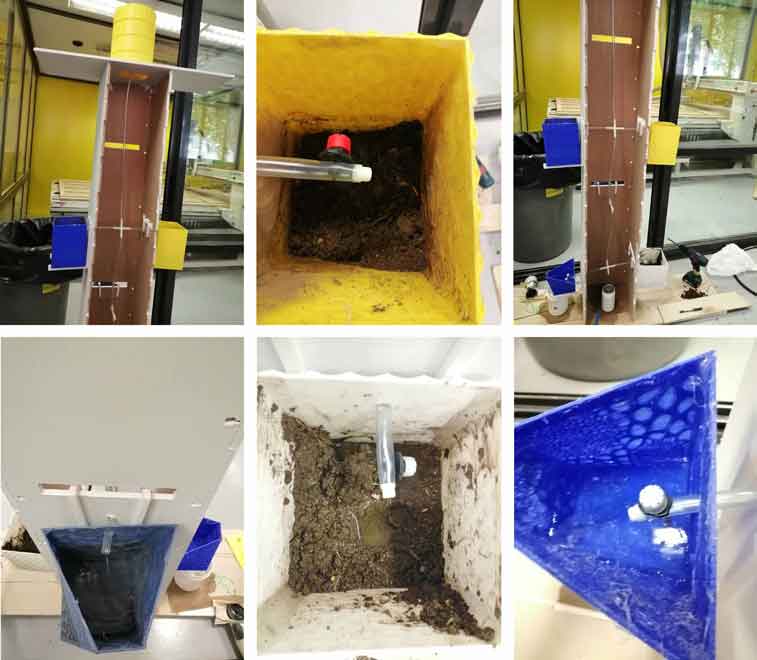
Pots holder and Connections
I designed the pot holders in a simple way to hold the pots and be hanged easily to the structure. The holders are strong enough to hold 3 kgs .
After doing several tests for the water flow between all the levels of the project I found that some of the connections need to be partially open and some half open in order for the water pressure to equal on all the pots.
Tanks
I designed two different tanks one will be for the nutrients from one side connected directly to the pipe comming from the air conditioner and from the other side it will be connected to the second tank which be directly connected to the pots.
Weight Test:
As per the volume calculations I have some pots that have 3042 cm3 and other less.
Water flow testing:
As we can see after the several trials and calibration of the pipes the water reached all the pots.
Sensors Testing:
I started with the main sensor the soil humidity sensor more details can be found in the Input Devices Week.
Since this is the main sensor I started by trying it using three different conditions of the soil. Wet, dry and perfect condition as per the sensor calibration values.
- less than 500 is too wet
- 500-750 is the target range
- higher than 750 is dry enough to be watered
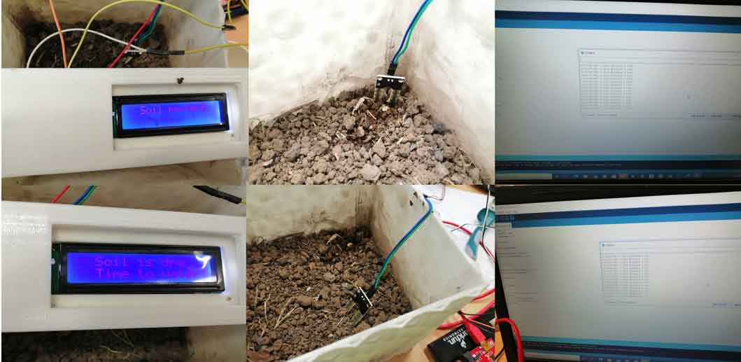
In test one the soil was in a perfect condition no need to water.
In test two the soil was dry as indicated on the LCD it is time to water.
So in this test I was testing the sensor, the code and the LCD.
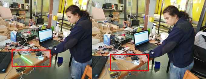
Second I tested the LDR sensor which will be connected to the grow lights. More details can be found in the Input Devices Week.
I tested the sensor with a condition:
LDR status is lower than 750 turn relay on and the LEDs will glow.
Third I tested the DHT22 sensor for the write humidity and temperature.
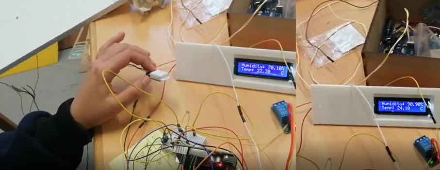
As a final step I combined all the sensors with the solenoid valve and LEDs to relays and to the LCD for a final testing before installing them inside the project.
Here I want to note that I faced a problem with the DHT22 sensor library. I had to remove all libraries and install them again and add the new library to the code until finally one of the libraries worked well.
Phase III: Automation System
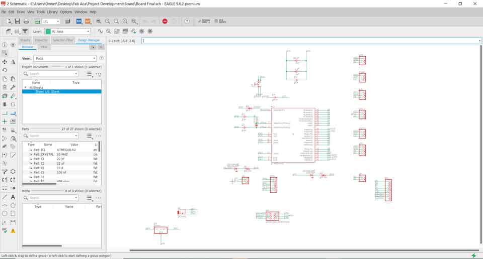
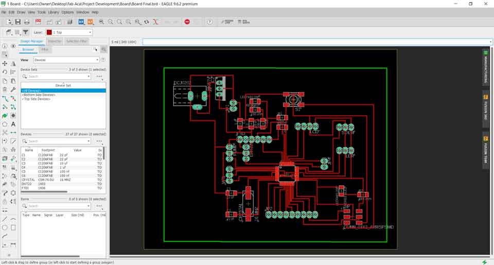
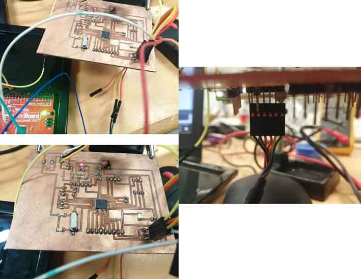
I designed my final PCB board taking into consideration all the needed components input and output devices to be included with all the functions of the project that the PCB will need to do.
Design considerations such as pin headers for all the needed sensors, the placement of the power jack and voltage regulator...
Main design considerations:
- FTDI pinout: I switched the TX and RX pins so I can directly connect the FTDI cable for programming.
- I added an ISP connection and connected the GND and VCC to it so I can program it for the first itme directly and in an easy way.
- I placed the capacitors and the crystal next to the microcontroller ATmega328P. Since capacitors smooth out any of the high-frequency noise in in the circuit, they should be near the microcontroller or else they will less effective.
Eagle Sketch:
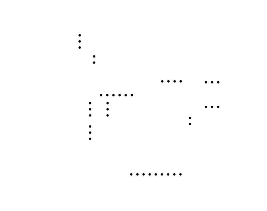
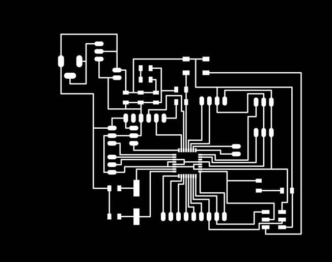
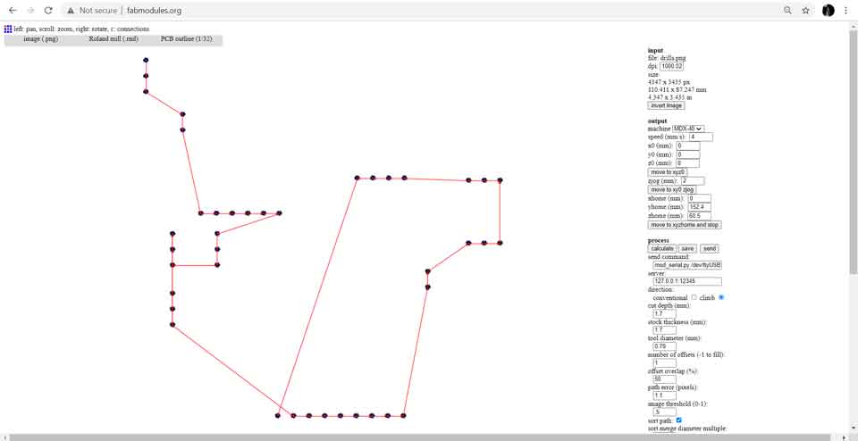
Exported drills, traces and outer cutout

Details about Electronic Design
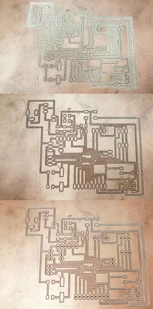
Milling the PCB:
Details about Electronic Production
To mill the PCB I started by generating the gcodes using Fab Modules.
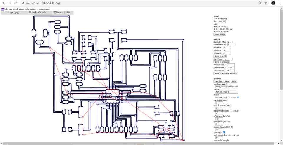
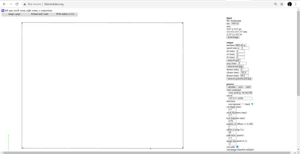
Producing the PCB
List of components:
- Microcontroller ATmega328p
- Crystal 16 MHz
- 2 Capacitors 22 pf each
- 2 Capacitors 100 nf each
- 1 Capacitor 1 uf
- 1 Capacitor 10 uf
- 1 Resistor 10 K
- 1 Resistor 499 Ohm
- 1 Resistor 100 Ohm
- Push Button
- Red LED
- Green LED
- 7805 voltage regulator
- Power Jack
- ISP 2X3SMD
- 2 Pin Header 1X2
- Pin Header 1X9
- 2 Pin Header 1X4
- 5 Pin Header 1X3
- FTDI Pin Header 1X6
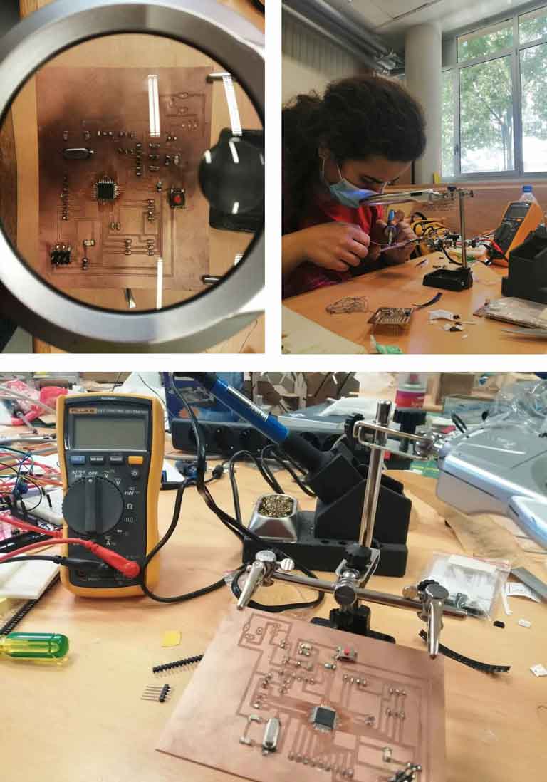
Soldering:
Phase IV: Programming
After soldering the components now it is time to program the board.
As a reference I used two previous weeks Electronics Design and Embedded Programming.
Details about Electronic Design
Details about Embedded Programming
Step I:
Sending bootlder via Arduino as ISP
Testing the board by uploading the blink test using an Arduino board as ISP to check my PCB before uploading my project final code.
Step II:
Connect the FTDI connection and test the board using a simple code before sending the final one.
Final Code:
By Ghinwa Azzi Fab Academy 2021
#include
#include
#include

const int ledPin = 8;
const int ldrPin = A0;

LiquidCrystal_I2C lcd(0x27,16,4);
dht DHT;

#define soilWet 750
#define soilDry 500
#define sensorPower 7
#define sensorPin A1
#define relay 6
#define DHT22_PIN 2

float hum;
float temp;


void setup() {
  lcd.init();
  lcd.clear();
  lcd.backlight();
  pinMode(sensorPower, OUTPUT);
  pinMode(relay, OUTPUT);
  digitalWrite(relay, LOW);
  digitalWrite(sensorPower, LOW);
  pinMode(ledPin, OUTPUT);
  pinMode(ldrPin, INPUT);
  Serial.begin(9600);
}


void loop() {
int moisture = readSensor();
  lcd.setCursor(2,0);
  Serial.print("Analog Output: ");

 if (moisture > soilWet) {
    lcd.print("Soil Dry");
     lcd.setCursor(2,1);
  lcd.print("Time to Water");
    digitalWrite(relay, LOW);
  } else if (moisture <= soilWet && moisture >= soilDry) {
    lcd.print("Soil Perfect");
  } else {
   lcd.print ("Soil Wet");
        lcd.setCursor(2,1);
  lcd.print("Stop Watering");
    digitalWrite(relay, HIGH);
  }
    delay(7000);

    int chk = DHT.read22(DHT22_PIN);
    hum = DHT.humidity;
    temp= DHT.temperature;
    lcd.setCursor(0,0);
    lcd.print("Humidity: ");
    lcd.print(hum);
    lcd.print("%");
    lcd.setCursor(0,1);
    lcd.print("Temp: ");
    lcd.print(temp);
    lcd.println("    C");
    delay(7000);

   int ldrStatus = analogRead(ldrPin);
   lcd.clear();
   lcd.setCursor(0,0);
   lcd.print("  LDR  ");
   lcd.setCursor(6,1);
   lcd.print(ldrStatus);
   delay(0);
   if (ldrStatus < 750) {
   digitalWrite(ledPin, LOW);
   }
   else {
   digitalWrite(ledPin, HIGH);
   }
   delay(7000);

 }

  int readSensor() {
  digitalWrite(sensorPower, HIGH);
  delay(10);
  int val = analogRead(sensorPin);
  digitalWrite(sensorPower, LOW);
  return val;
}
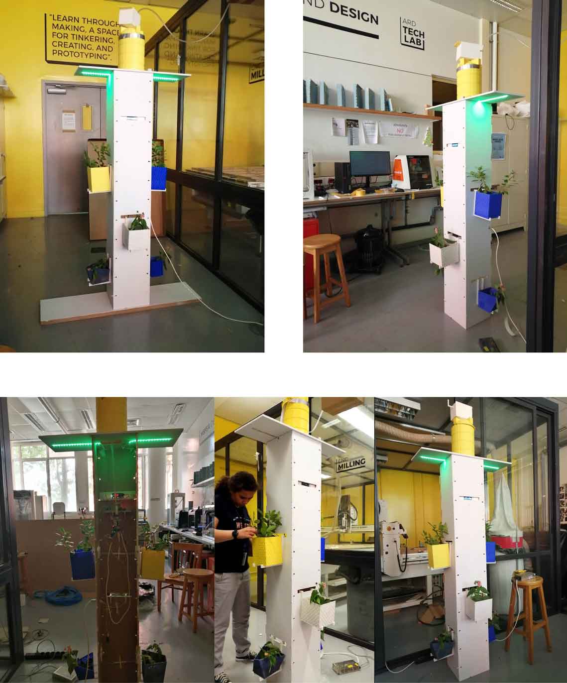
Phase V: Assembly
Main Structure
As mentioned previously I assembled the main structure in the Computer Controlled Machining Week.
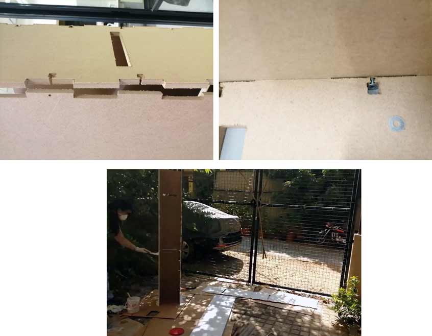
I assembled all the structure then in the final week after all the testings are done I painted the wood with a grey water based paint.
Water Tubes
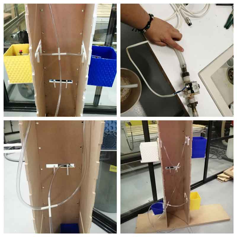
In this step the main problem that I was facing is the water leakage between the tubes and connections between the pots and the tank. This is because of the 3D printing process. I solved this problem in two ways first I printed the connections at a high a resolution layer height 0.05 mm and second by lowering the water flow in the pipes so the water goes slowly into pots without having excessive water in the pipes.
Also I added water pressure compensating dripper at the end of the pipes to control the dripping into the plants.
Electronic Parts
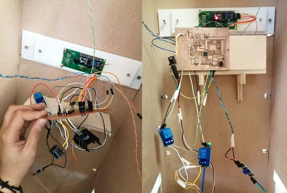
Final Result
Summary:
As I finished this project using different skills to acheive this final result and most of what I aimed for in this project. I still have some point to study and tackle in the future to acheive a better results.
Some of the points are:
The grow lights intensity and the amount of light needed for the plants. This should be acheived by having a study on a different time frames and seasons to check the growth of the plans.
The water intensity and flow from the tubes to the pots.
Study the amount of nutrients needed for the plants.
Also since the project is connected to water supply and the material and electronics should be waterproof and safe from any leakage in order not to create problems.
To improve this project maybe another tank should be added to collect water in case the AC was not working in a certain day and the plants need water.
The structure files can be dowloaded from Computer Controlled Machining Week.
The pots files can be dowloaded from 3D Scanning and Printing Week.
Eagle files Eagle.
Code Code.
Other files Other files.

This work is licensed under a Creative Commons Attribution-NonCommercial-ShareAlike 4.0 International License