Group Assignment
Send a message between two projects.
Individual Assignment
Design, build, and connect wired or wireless node(s) with network or bus addresses.
Individual Assignment
In this assignment I am going to learn the difference between Serial UART Connection, Serial Peripheral Interface (SPI), and the I²C–Inter-Integrated Circuit then I will test the bluetooth connection.
Serial Communications
Serial communication is the most widely used approach to transfer information between data processing equipment and peripherals. In general, communication means interchange of information.
In embedded system, Serial communication is the way of exchanging data using different methods in the form of serial digital binary. Some of the well-known interfaces used for the data exchange are RS-232, RS-485, I2C, SPI etc.
Serial communication can take many forms depending on the type of transmission mode and data transfer. There will be a source (also known as a sender) and destination (also called a receiver) for each transmission mode.
Serial UART ConnectionsUniversal asynchronous receiver-transmitter (UART) is one of the simplest and oldest forms of device-to-device digital communication.
UARTs communicate between two separate nodes using a pair of wires and a common ground.
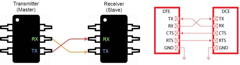
UART communication scheme:
The TX (transmit) pin will be connected directly to the RX (receive) pin and vice versa.
UART is a single-master, single-slave protocol, where one device is set up to communicate with only one partner.
All data sent on the TX pin is translated and this parallel information is transformed into serial and is transmited to the receiving counterpart.
RX pin the second UART receives the data and transforms it back into parallel to communicate with its controlling device.
Serial Peripheral Interface (SPI)
What is SPI?
- Serial Peripheral Interface is a synchronized serial communication protocol. It provides full communication at very high speeds. SPI is a master – slave type protocol that provides a simple relation between a microcontroller and its peripherals.
- In UART the communication happens over RX and TX connections, while in this type of communication, there is no control over the data sent or whether the transmitter and receiver have same data rates.
How SPI Works?
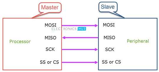
In SPI the devices are connected in a Master – Slave relationship. One device is considered the Master of the bus (usually a Microcontroller) and all the other devices are considered as slaves.
The SPI 4 pins are:
- MOSI: Master–Out / Slave–In: MOSI transmits data from the master to the slave.
- MISO: Master–In / Slave–Out: MISO MISO transmits data from the slave to the master.
- Serial Clock (SCLK): a clock signal that is sent from the master.
- Chip Select (CS) or Slave Select (SS): it is controlled by the master device and indicates that the master is sending data to or requesting data from the corresponding slave device.
- Serial Clock (SCLK): It is also controlled by the master device and a new data is sent out with each clock cycle.
The GND connection is common between all devices.
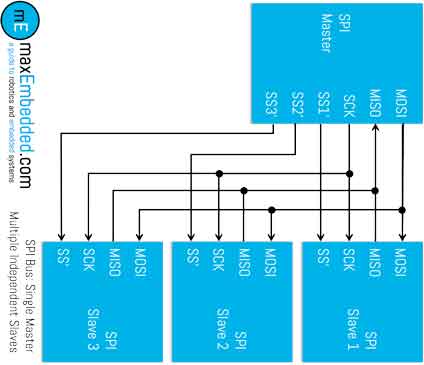
Description of the above diagram:
We can see in the above diagram that we have multiple SPI devices sharing the same MISO, MOSI, and CLK lines of master.
We have three slaves having common SCLK, MISO, MOSI connected to the master.
The SS or CS is separated by individual SS or CS pins (SS1, SS2, SS3) from the master to each slave. In this way when the SS or CS pin is LOW the master can communicate with the slaves.
I²C – Inter-Integrated Circuit
I²C Circuit Communication:
The term IIC stands for “Inter Integrated Circuits” it refers to I squared C or as 2-wire interface protocol (TWI).
I2C is a synchronized communication protocol meaning, both the devices that are sharing the information must share a common clock signal.
To share information there is only two wires: first one is the clock signal and the second is for sending and receiving data.
I²C Circuit Connections:
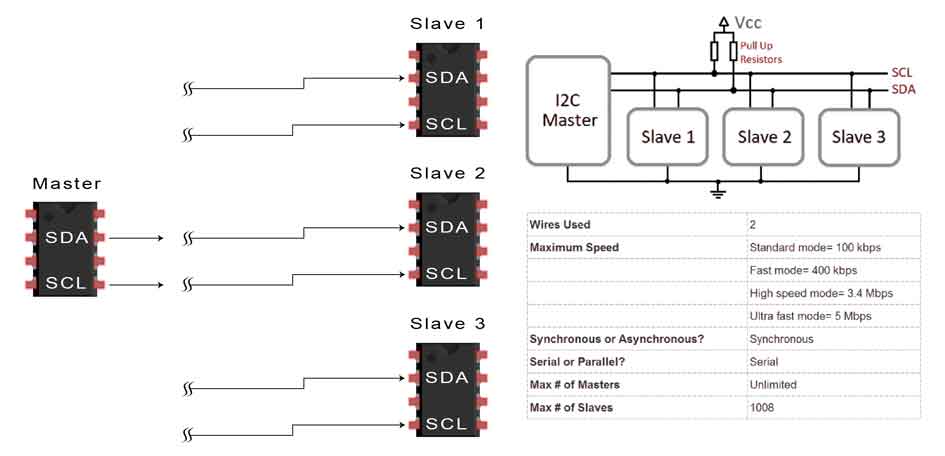
The two wires mentioned earlier are connected to two devices. The first device will be the master and the second device will be the slave.
Communication will always be between a master and a slave. Noting that more than one slave can be connected to a master.
Serial Clock (SCL): Shares the clock signal generated by the master with the slave.
Serial Data (SDA): Sends the data to and from between the Master and Slave.
I²C Interface:
- SDA: Serial Data
- SCL: Serial Clock
- GND: Ground
The GND connection is common between all devices.
Testing Codes:
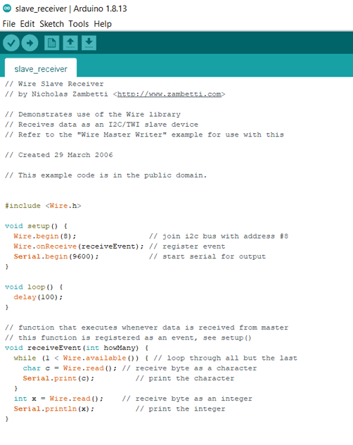
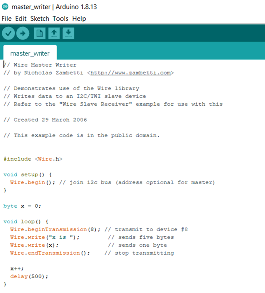
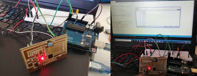
I used two Arduino UNO boards to test the above Master and Slave codes.
The codes are from the examples section in Arduino.
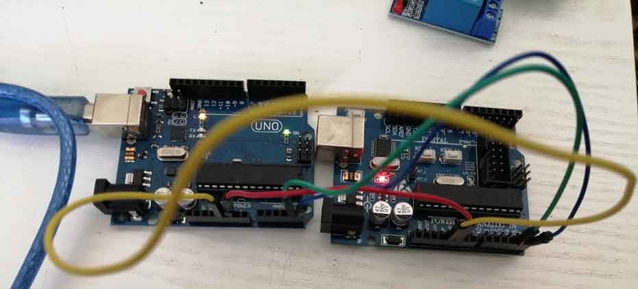
Connections:
- A4 SDA connected to A4: Green wire
- A5 SCL connected to A5: Orange wire
- VCC 5V to VCC: Yellow wire
- GND to GND: Red Wire
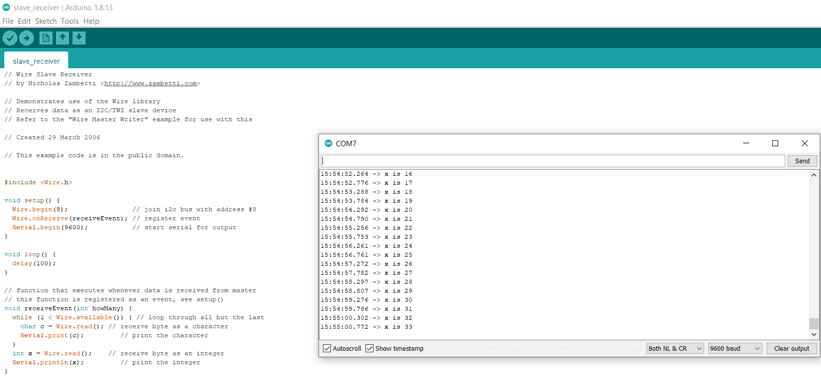
Explanation:
In the above capture and video the master code is sending the x value. This value which is increasing at each loop and the slave is receiving the values that are appearing on the arduino serial monitor.
My Board:
Using my board that I desinged in Embedded Programming.
I connected my board as a master and used the Arduino UNO as a slave using the I²C communication protocol.
Connections:
- A4 SDA on my board connected to A4 pin on Arduino: Yellow wire
- A5 SCL on my board connected to A5 pin on Arduino: Green wire
- GND on my board connected to GND pin on Arduino: Purple wire
Same code was used as the previous test.
Bluetooth Connection
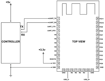
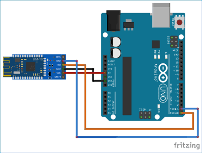
In this section wireless connections I am going to use the HM-10 Bluetooth module to connect it with an arduino board and do some tests.
The connections are:
GND will be connected to the GND pin
VCC will be connected to the VCC pin 3.3V as unducated in the datasheet.
TX on the bluetooth module goes to the RX or Pin 0 on the Arduino board.
RX on the bluetooth module goes to the TX or Pin 1 on the Arduino board.
Test:
I will connect the HM-10 bluetooth module to the arduino board with an LED and a resistor.
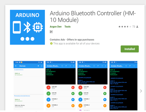
Then I will download the Arduino Bluetooth Controller (HM-10 Module) application on my smartphone.
Then I prepared the arduino code and it will be the below:
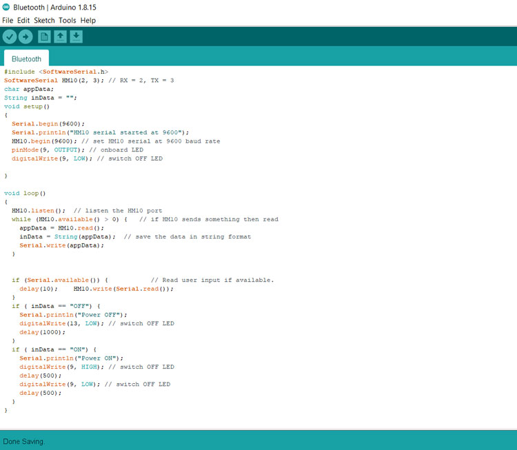
The above code is from an online page describing how to use the bluetooth module (how2electronics) and I modified it by changing the pin numbers and the readings that will appearon the application.
In the application I searched for the module and established a connection.
Then I entered the messages LED OFF and LED ON.
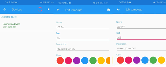

The messages will be created and appear directly when we enter the application.
Once we click LED ON the LED will shine and when we click LED OFF it will turn OFF.
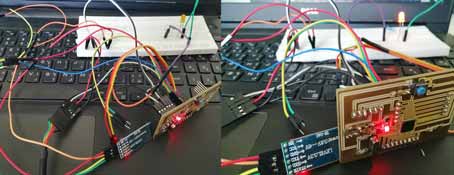
My Board:
I did the same steps as the above while using the Arduino UNO but this time I connected my board.
Group Assignment
Here you can find our group assignment LINK
The purpose of this project is to send a message between two projects.
We will learn on how to connect two or more microcontroller boards, using different networking methods to communicte data between them.
What is Networking and Communication?
Data communications refers to the transmission of this digital data between two or more computers and a computer network or data network is a telecommunications network that allows computers to exchange data.
Send a message between two projects
Issa used his Board B1 and connected it to my Board using I2C connection: my board will be the master with a push button connected to it and Issa's Board will be the slave with the led connected on pin13. It will turn on when we push the button on the master board and below are the codes:
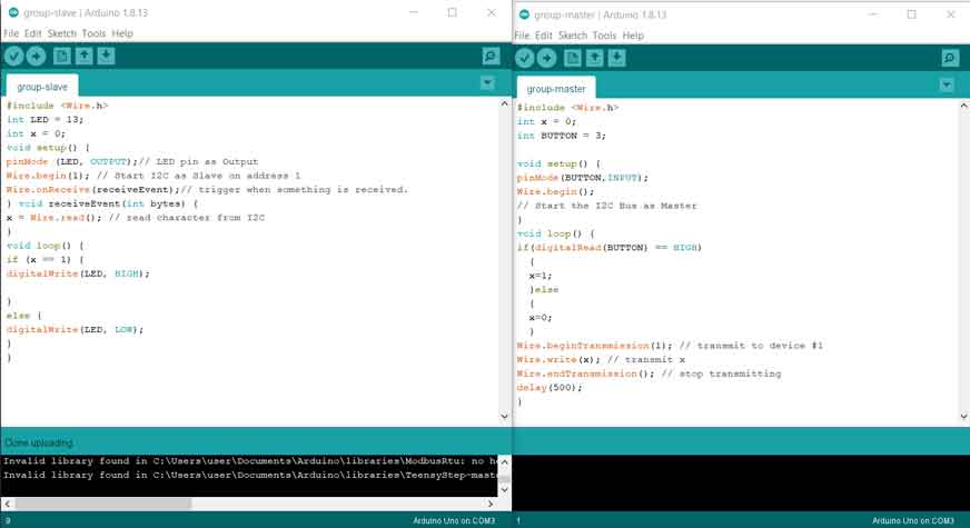
Connections:
VCC to VCC (blue wire)
GND to GND (purple wire)
A4(SDA) to A4 (green wire)
A5(SCL) to A5 (yellow wire)
Reference: Electronics Hub, All About Circuits, AnalogDialogue, Circuit Basics, Circuit Digest, Arduino Project Hub

This work is licensed under a Creative Commons Attribution-NonCommercial-ShareAlike 4.0 International License