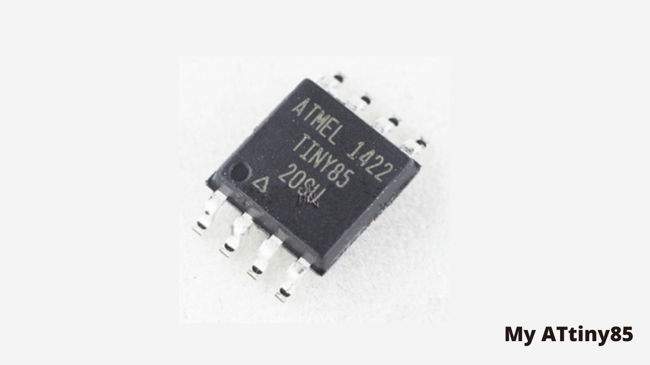
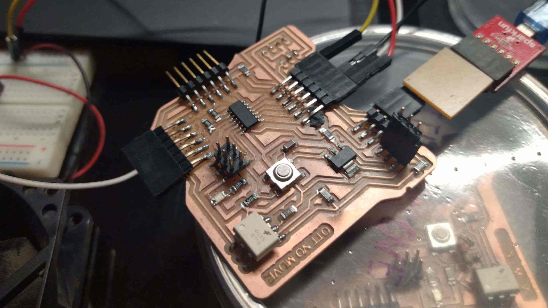
Stefany Casanova and I decided to use the ATtiny 1614 microcontroller for our final boards, however at first we were doing our first tests with the Attiny 85, so here we will share the research we did with both.
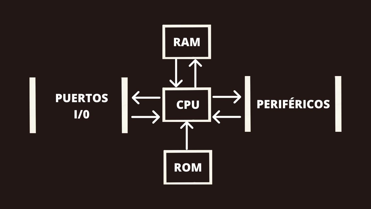
But first, what is a microcontroller? A microcontroller is an integrated circuit that contains a central processing unit (CPU), memory units (RAM and ROM), input and output ports and peripherals. These parts are interconnected inside the microcontroller, and together they form what is known as a microcomputer. A microcontroller is a complete microcomputer encapsulated in an integrated circuit.
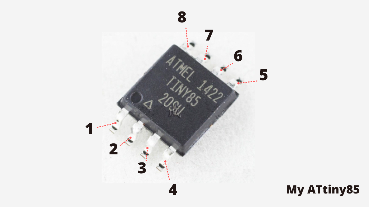
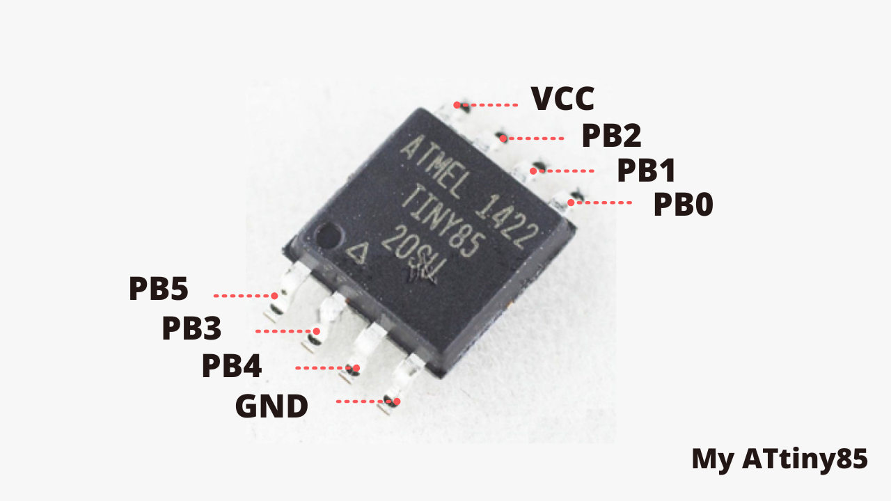
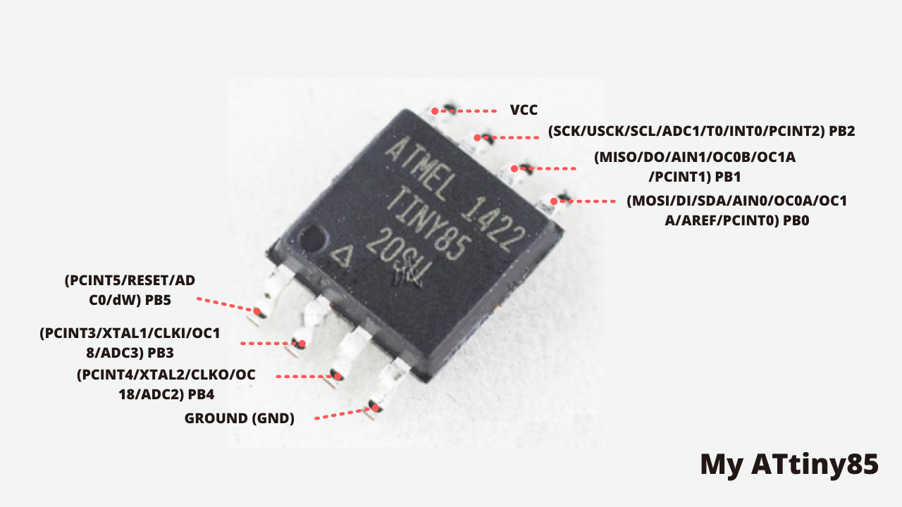
ATtiny 85 detailed pinout
What does each one mean?
VCC - GND: They mean direct current voltage and ground respectively, the VCC usually means that you must connect the positive terminal of the direct current source you are going to use, in the case of GND it is a 0V reference.
PB0 - PB1 - PB2 - PB3 - PB4 - PB5: In this microcontroller every pin except power pin. ALL input/output pins are connected to bidirectional Input/output register through internal pull-up registers. Any pin can be used for input or output purpose but first, it should be described in a program which function it should follow.
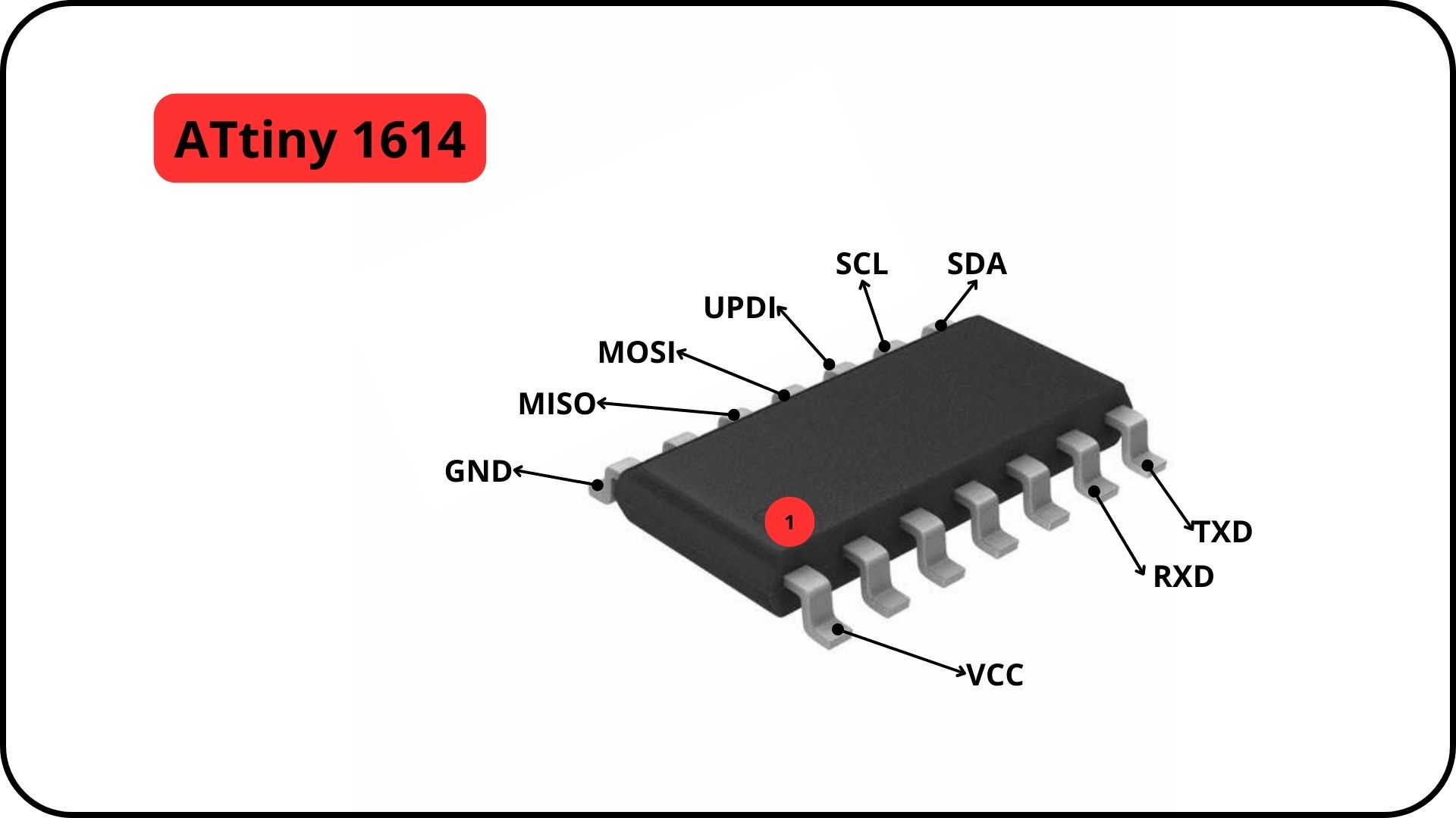
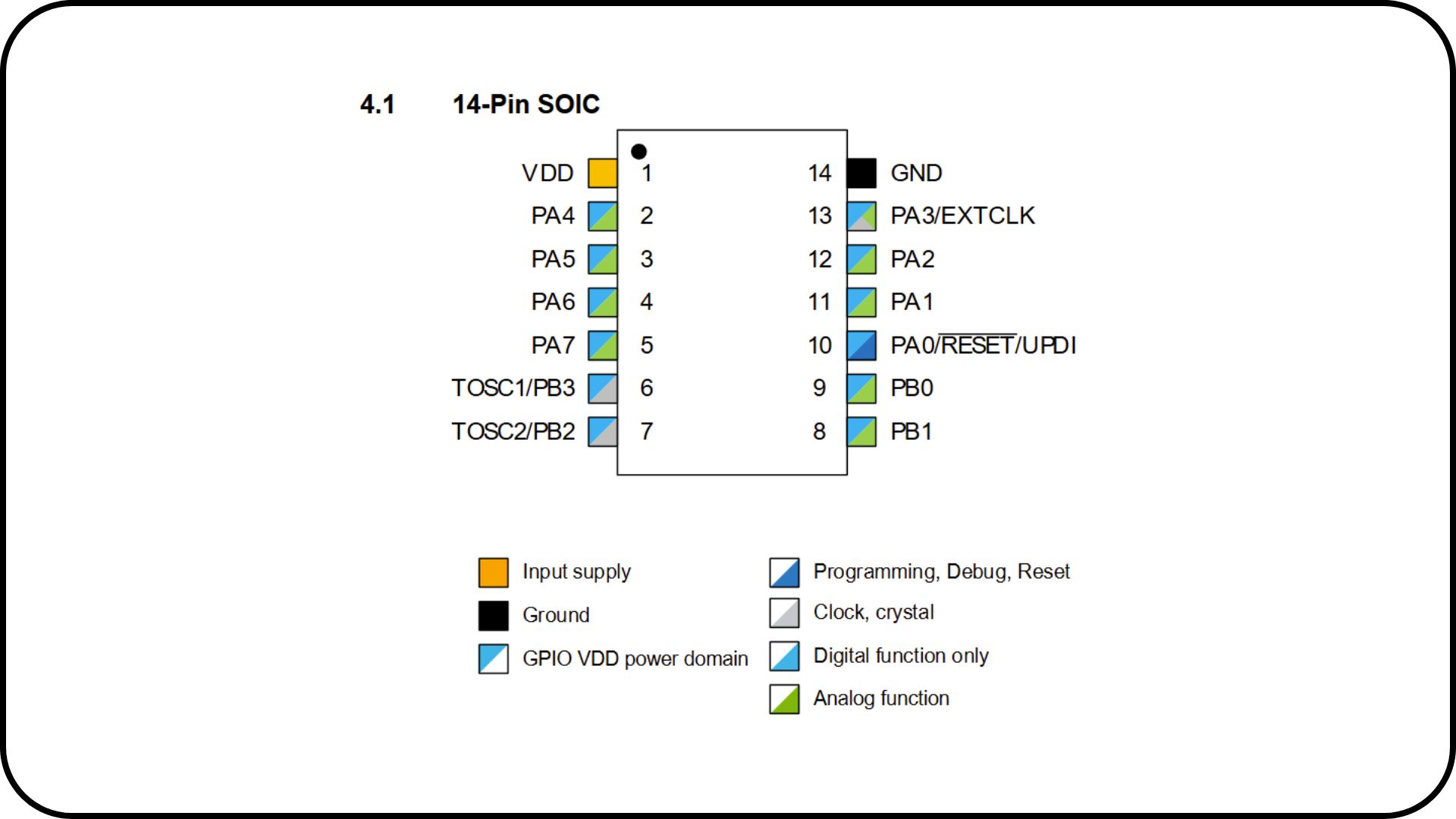
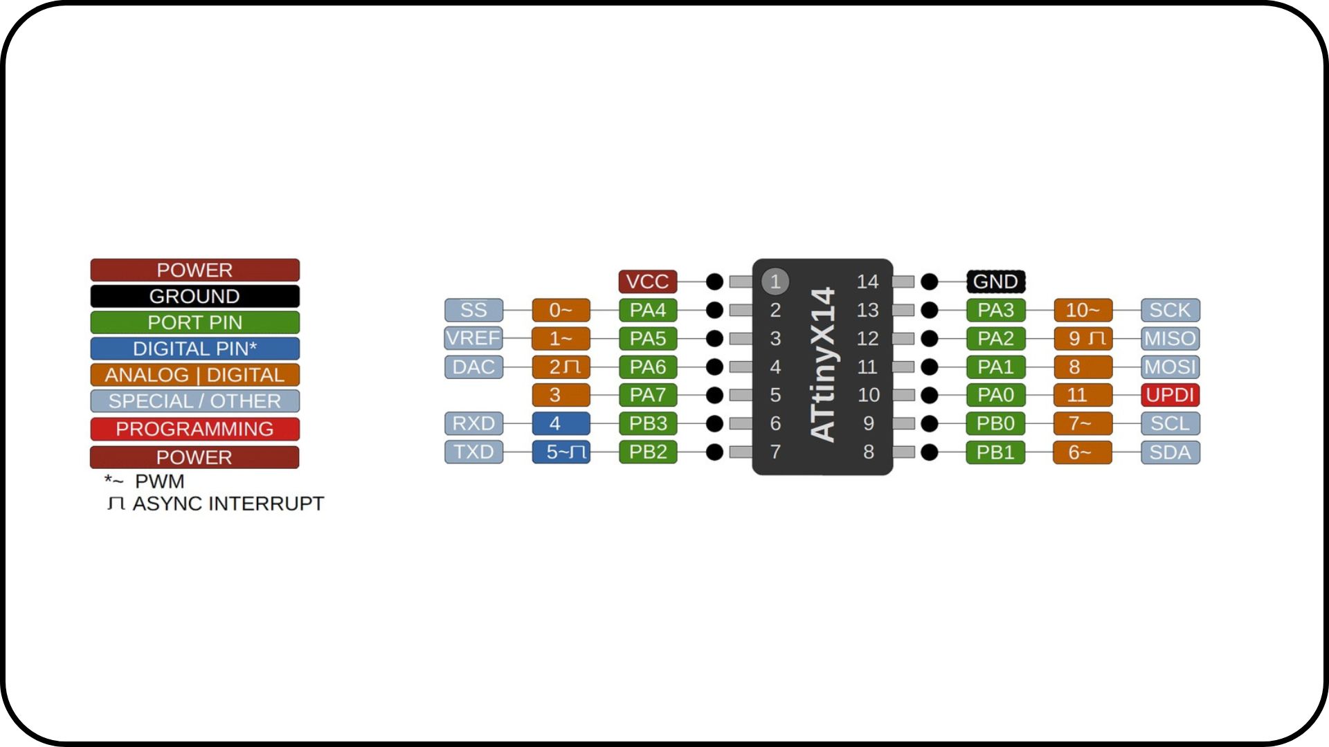
ATtiny 1614
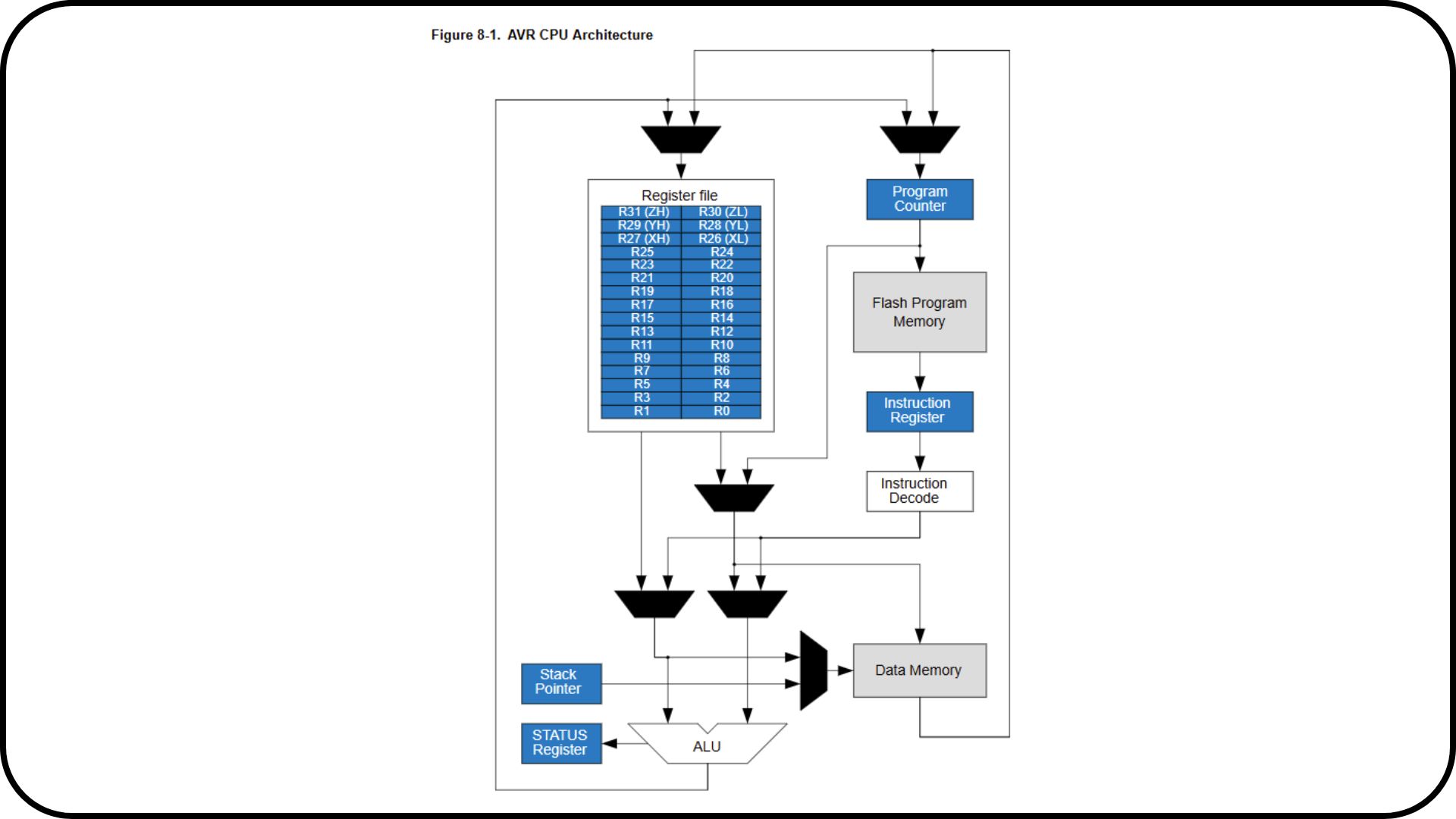
The ATtiny1614 microcontroller is part of the 8-bit AVR family of microcontrollers manufactured by Microchip. This model is popular for its energy efficiency, compact size and processing power, making it ideal for embedded and low-power applications. Its main features, architecture and functionalities are described below:
Main features of the ATtiny1614
Architecture:
- Based on 8-bit AVR architecture with RISC instructions.
- High performance AVR core that executes instructions in one clock cycle.
- Support for vector interrupts and configurable priority.
Memory:
- Flash: 16 KB, system programmable.
- SRAM: 2 KB.
- EEPROM: 256 bytes for non-volatile data storage.
Peripherals:
- Up to 14 GPIO (General Purpose Input/Output) pins.
- Integrated UART, SPI and I2C (TWI) for serial communication.
- 10-bit ADC with multiple channels (8 ADC channels).
- Analog comparators.
- PWM (Pulse Width Modulation) for control of motors and LED lights.
- 16-bit and 8-bit timers with different operation modes.
Operating voltage:
- Wide operating range from 1.8 V to 5.5 V.
Clock:
- Internal oscillator up to 20 MHz.
- Possibility of using an external oscillator for higher accuracy.
Power consumption:
- Designed for low power consumption applications.
- Power saving modes, such as:
.
Sleep Mode: Reduces consumption to a minimum while keeping peripherals active.
.
Power-Down Mode: Maximum power saving.
Programming:
- Programmable via UPDI (Unified Program and Debug Interface).
- Compatible with development tools such as Atmel Studio and Microchip MPLAB.
Programming:
- Designed for low power consumption applications.
Architecture:
- 8-bit AVR core:
. Ability to perform basic arithmetic calculations and operations with high efficiency.
. RISC instruction set optimized for performance and compact code size.
- Register bank: General Purpose Registers (GPR) that allow operations to be performed without accessing RAM, increasing execution speed.
- Memory space: Segmented memory for programs (Flash), data (SRAM) and non-volatile storage (EEPROM).
- Peripherals and buses: Peripherals are connected to the core through internal buses to facilitate fast communication between them.
Functionalities:
- Digital control: Ideal for applications such as control of LED lights, motors or sensors.
- Data acquisition: Integrated ADC to convert analog signals to digital (such as temperature, light or pressure sensor readings).
- Serial communication: Ability to interface with other devices via UART, SPI and I2C.
- Timing and signal generation: Timers to perform scheduled tasks, PWM signal generation for external device control.
- Low power applications: Ideal for systems that require continuous battery operation, such as portable devices or IoT sensors.
Common applications
- IoT (Internet of Things) projects.
- Home automation controllers.
- Portable devices.
- Sensors with local processing.
- Intelligent lighting systems.
- Educational electronics and compact prototypes.
Conclusions on the ATtiny1614 microcontroller
-
Efficiency and simplicity: The ATtiny1614 stands out for its 8-bit AVR architecture, which combines simplicity and efficiency, offering performance suitable for basic control and processing applications. Its RISC instruction set ensures that operations are fast and optimized, executing in a single clock cycle.
-
Compact and versatile design: Its small size and flexibility in the configuration of its 14 GPIO pins make it ideal for projects that require integration in tight spaces or portable systems, such as IoT devices or simple electronic controls.
-
Robust peripheral capabilities: Includes peripherals such as 10-bit ADCs, timers, serial communication (UART, SPI, I2C) and PWM generation, enabling its use in a wide range of applications, from motor control to analog signal processing.
-
Low power consumption: Designed for low-power applications, the ATtiny1614 features power-saving modes that extend battery life, making it ideal for portable and sustainable projects.
-
Ease of programming and development: Its compatibility with modern interfaces such as UPDI and tools such as MPLAB X or Atmel Studio makes it easy to program and debug, being accessible for beginners and professionals alike.
-
Practical applications: This microcontroller is highly functional in interactive and entertainment projects, such as controlling LEDs, sensors, motors and measurement devices. It is especially useful in systems that do not require more complex processors or large memory capacities.
-
Cost-benefit ratio: It offers a cost-effective solution without compromising important functionalities, being a preferred choice for educational projects, prototypes and simple commercial devices.
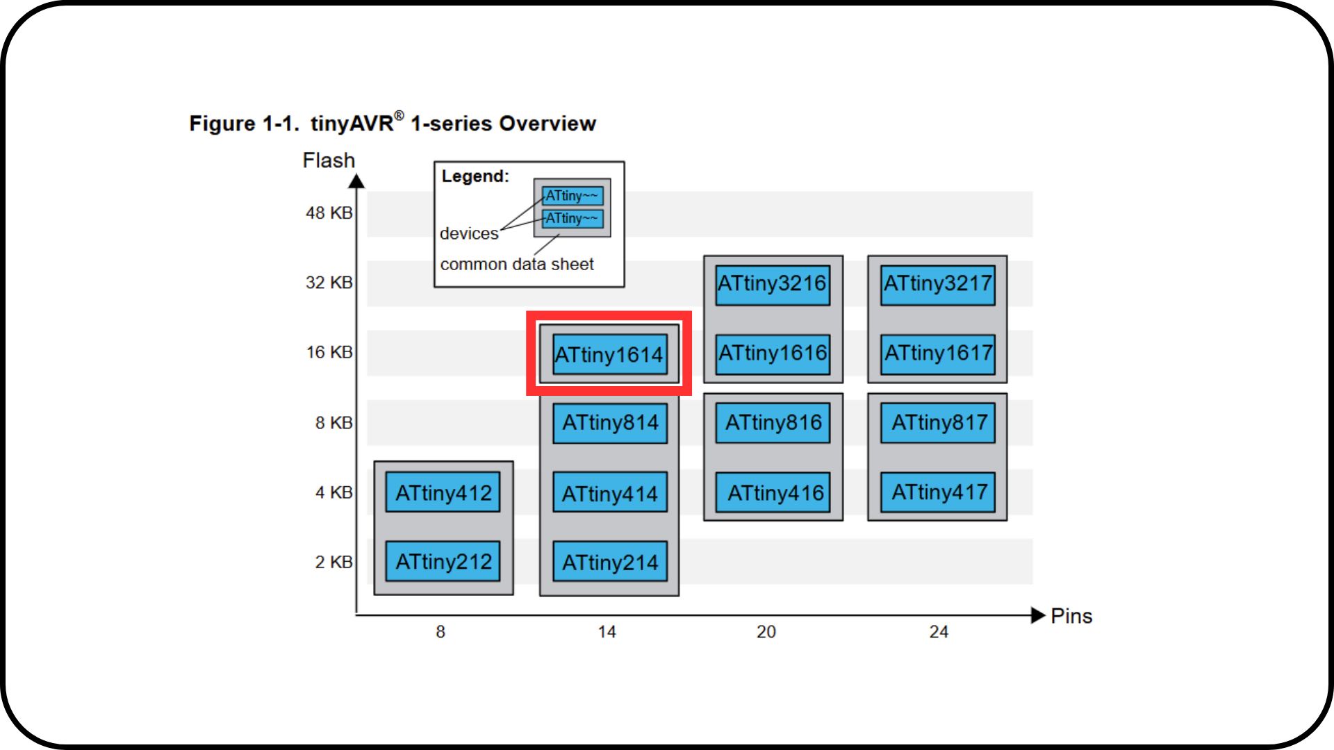
Other AVR series microcontrollers (Microchip):
ATtiny816/814:
Features:
- Same 8-bit AVR architecture.
- Flash memory of 8 KB (for the ATtiny816) and 4 KB (for the ATtiny814).
- Less SRAM and EEPROM memory compared to the ATtiny1614.
- UPDI compatible for programming and debugging.
Differences:
- Fewer GPIO pins.
- Similar peripheral functionality, but less expandability.
ATtiny3216/3217:
Features:
- 32 KB of Flash memory (twice as much as ATtiny1614).
- More GPIO pins (up to 20 pins).
- Same peripheral capabilities: ADC, PWM, timers, and serial communication.
- Ideal for projects requiring more memory capacity.
Differences:
- More expensive and physically larger.


