Twelfth week

Twelfth
class

In this class I put myself to the test once again, the whole world of electronics is quite complicated and wide but when you do the research and little by little you get to know how each piece works, it is incredible.

I am definitely learning a lot with each weekly challenge, my recommendation would be to take with a lot of patience the understanding and with a lot of strategy to be able to reach the goals in the times requested.

So I invite you to join me in this new stage, if you have had many doubts with some parts of this challenge, it is possible that this documentation may be a little clearer, I felt a little lost at the beginning but I made it! 💪🥰


What's coming up


10

First Assignment

Grupal Assignment

In this task, together with Stefany Casanova , we explored the power consumption of a system based on an ATtiny1614 microcontroller connected to an MG996R servo. Using a digital multimeter, we measured both voltage and amps in different states of the device, facing technical challenges such as series measurement for current. This experience not only allowed us to document the energy behavior of the circuit, but also to learn valuable lessons about the handling of measuring instruments and the importance of teamwork in electronics projects.💪

The beginning


In this task, we worked as a team to measure the power consumption of an output device connected to a custom board designed as part of our final projects. The board, based on an ATtiny1614 microcontroller, was used in conjunction with an MG996R servo as the output device.

The main objective was to analyze both the voltage (V) and current (A) consumed by the system, which is essential to evaluate its energy efficiency. To do this, we used a digital multimeter and performed measurements in different states of the system: at rest and during servo activity. These measurements were essential to understand the variations in power consumption and to determine whether the power supply can meet the demands of the circuit under various operating conditions.


Current (A)


Voltage (V)


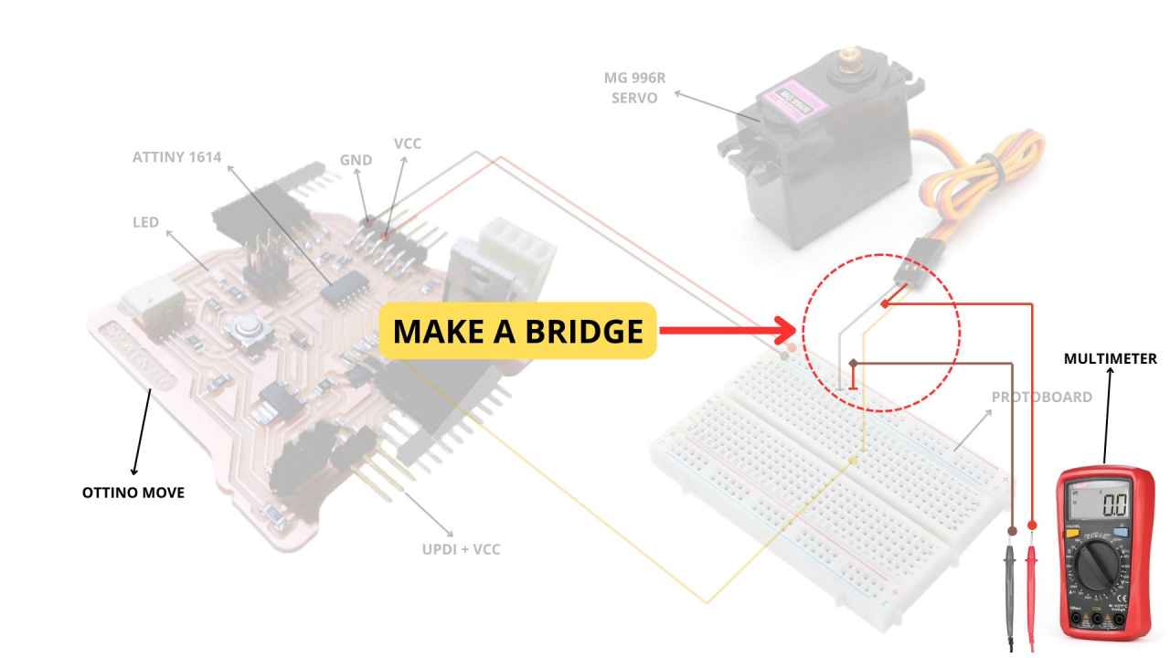
During the process, we faced technical challenges, such as understanding and correctly measuring amperes. One of the most complex moments was setting up a bridge with the multimeter to measure series current, as it required interrupting the circuit and properly connecting the measuring device. These difficulties taught us the importance of understanding electrical connections and the correct handling of measuring instruments.

In the end, we were able to obtain accurate data on both the voltage and amperes consumed by the system. This experience not only allowed us to document the energy behavior of the circuit, but also strengthened our practical skills in electronics and measurement, essential for the development of the final project. In addition, we learned significantly about teamwork and technical problem solving. 💪🥰

CONNECTION DIAGRAM:


Measure the power consumption of an output device


Next we share in detail how we get the measurements. It is important to note that if you do not know how to use the multimeter, you should be guided by the diagrams, otherwise, you will not be able to get the measurements correctly.

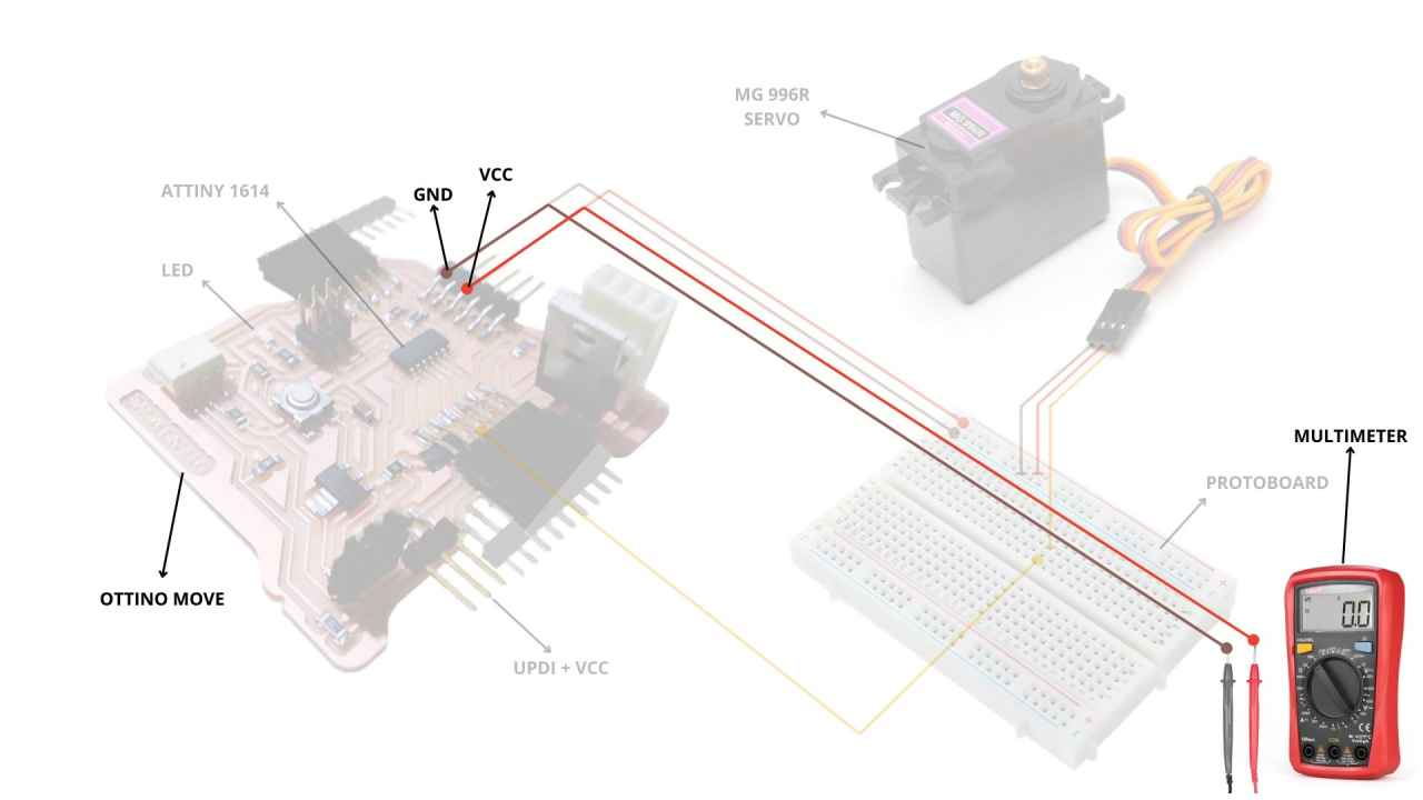
Voltage


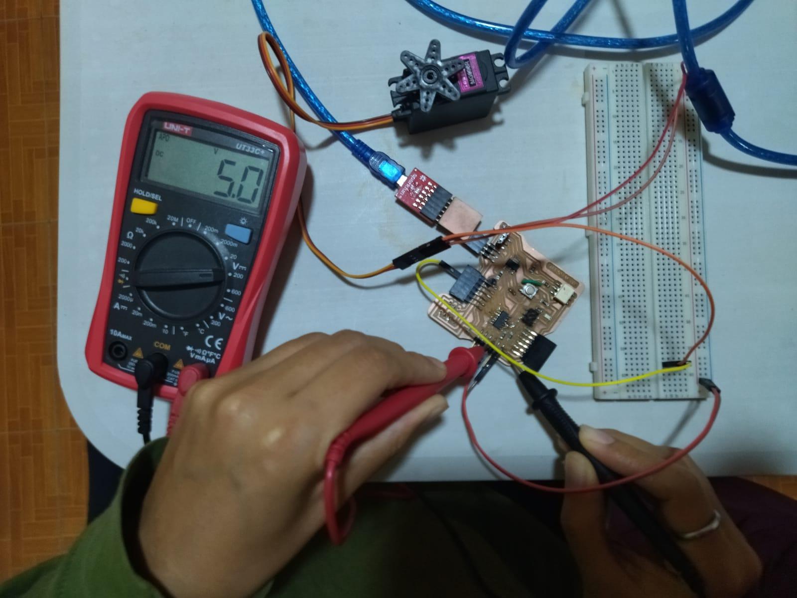
To perform the measurements, We set the multimeter to DC voltage mode and measured in parallel between the power pin (VCC) and GND of my system. In my case, the code loaded into the ATtiny1614 caused the servo to move at different angles (0°, 30°, and 60°), while the LED turned on and off in sync with each movement.

Results Obtained


Measured Voltage:
1. During the measurements, the system voltage stabilized at 5.0V, confirming that the power supply is adequate to operate both the ATtiny1614 and the MG996R servo.
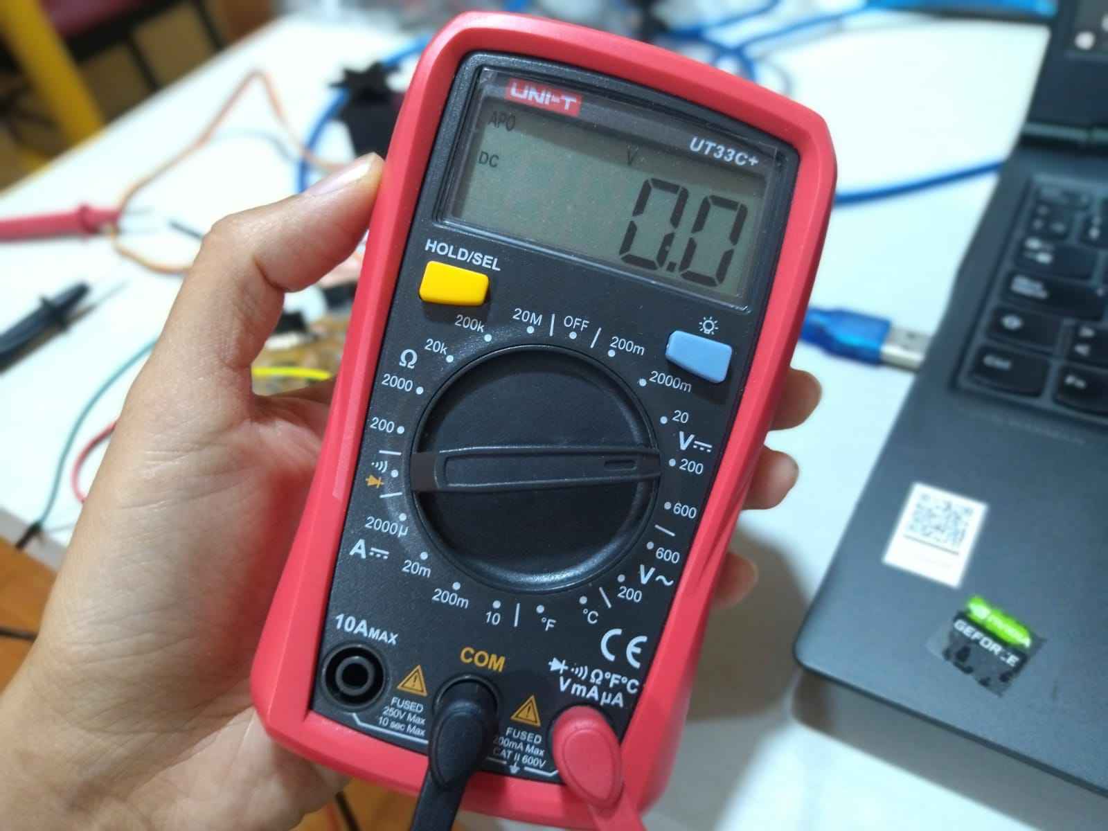
2. Slight initial oscillations were observed when the multimeter was turned on, possibly due to circuit stabilization or servo start-up.

Voltage Analysis


1. Voltage Stability:
The system maintained a constant voltage of 5.0V during all operations, which is critical to ensure proper operation of the microcontroller and servo.
2. Initial oscillations:
These could be due to the natural behavior of the system during connection of the multimeter and start of operations. To mitigate them, the use of a decoupling capacitor in the power supply could be considered.

HOW TO CONNECT - VOLTAGE:


Voltage (V)


Amperios


We now use the digital multimeter in mA current measurement mode to observe the power consumption during output device operations.

Results Obtained


Measured Current:
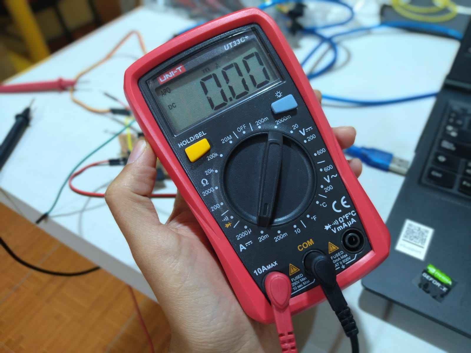
During the measurement, the current oscillated to a maximum value of 150 mA (0.15 A) when the servo was moving.
At rest (no servo motion), the current consumption was significantly lower, around 50 mA.
Multimeter Status:
The multimeter was set correctly in the milliampere (mA) range, which allowed accurate readings of the system consumption to be obtained.

Current Consumption Analysis


Current Variation:
The increase in current up to 150 mA is consistent with the characteristics of the MG996R servo, which has a higher consumption when moving, especially if it encounters any resistance or load.
The low idle consumption indicates that the system is efficiently designed to minimize power usage when the servo is not active.
Power Supply Review:
The power supply used is adequate, as it can smoothly handle the increased consumption during servo movements.
Maximum Power Calculation:
With the voltage of 5V and the maximum consumption of 150 mA, the maximum power consumed by the system can be calculated as: P=V×I=5 V×0.15 A=0.75 WP = V \times I = 5, \text{V} \times 0.15 \, \text{A} = 0.75 \, \text{W}P=V×I=5V×0.15A=0.75W This indicates that the system is relatively energy efficient.

HOW TO CONNECT - CURRENT:


Current (A)


10

Second Assignment

Individual Assignment
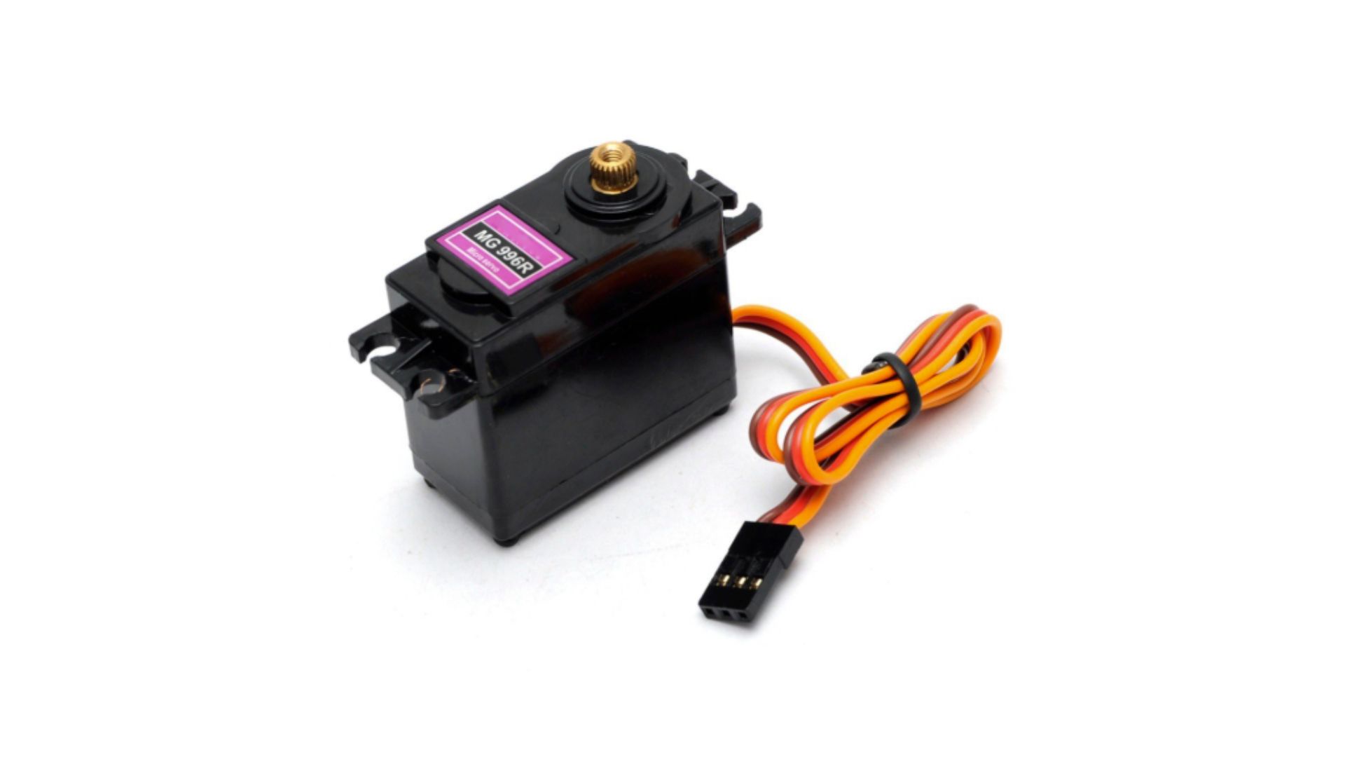
MG996R

This week we are asked to add an output device to a microcontroller board that I have designed and program it to do something.
In my case I chose to work with a servo motor so I could analyze the operation.

First exploration


The MG996R is a servo motor widely used in robotics projects and electronic prototypes because of its power, precision and versatility. In my case, I am using it on a board that has an ATtiny 1614 microcontroller, so I am going to explain how it works and how it is integrated in this kind of projects.

Features of the MG996R


First, this servo motor has a fairly high torque capacity: up to 11 kg/cm if powered by 6V, which makes it ideal for moving heavy parts or systems that need force. In addition, it can rotate within a limited range of 0° to 180°, which is typical for servos of this type.

It is controlled via three wires:
- Red: Positive power (5V or 6V, depending on the source).
- Brown: Ground or GND.
- Orange: The PWM signal, which is what tells the motor what position it should be placed in.

The pulse width in the PWM signal defines the angle:
- 1 ms (millisecond) moves the servo to angle 0°.
- 1.5 ms moves it to 90°.
- 2 ms sets it to 180°.

The total period of the signal must be 20 ms (i.e. a frequency of 50 Hz).

Control of MG996R with ATtiny 1614


The ATtiny 1614 is a small but very capable microcontroller. It generates the PWM signal needed to control the MG996R using one of its timers. However, there are a few important things to consider to make everything work well:

1. Power supply: The MG996R draws quite a bit of current, especially under load. It can require up to 2.5 A. Therefore, we cannot power it directly from the ATtiny or from a small regulator. In my project, I use an external power supply that delivers 5V or 6V with sufficient current.
2. Ground connection: In order for the microcontroller and the servo motor to work together, the grounds (GND) of the power supply and the ATtiny must be connected. This ensures that both components share the same reference point.
3. Microcontroller protection:Since the servo can generate electrical noise or current spikes, I added protection components such as a capacitor near the servo power supply and, if necessary, a diode to prevent damage.
4. Advantages of the ATtiny 1614: This microcontroller has multiple PWM pins, which means I can control more than one servo motor if I need to. Also, with its memory and capacity, it can execute precise instructions for dynamic movements.

Practical considerations


The MG996R is robust, but there are some details to be considered:
- Under load, it can generate electrical interference. Using capacitors helps to stabilize the power supply.
- Calibration is important. If we do not adjust the servo limits properly, we can strain the motor and damage it over time.
- This servo has good motion resolution, allowing fine adjustments, which is ideal for applications that require precision.

How I use it in my project


In this case, I am integrating it into a system controlled by the ATtiny 1614. My board generates the PWM signal to move the servo to the desired angles. I also have a dedicated power supply to ensure that the servo receives enough current without affecting the microcontroller. I am using this servo motor to control a mechanical motion in an interactive project, and its force capability makes it perfect for this task.

If anyone is considering using the MG996R, I would recommend that they first check the power requirements and how the PWM signals are generated, but overall it is a very reliable and powerful component for projects of this type.

My code


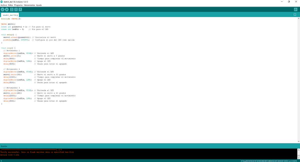
Below I share the code I used to perform my test:
 
								
//Mayra Ascencio Calderón
//Fab Academy 
//Summary

#include 

	Servo servo1;
	const int pinservo1 = 1; // Pin para el servo
	const int ledPin = 8;    // Pin para el LED
	
	void setup() {
		servo1.attach(pinservo1); // Inicializa el servo
		pinMode(ledPin, OUTPUT);  // Configura el pin del LED como salida
	}
	
	void loop() {
		// Movimiento 1
		digitalWrite(ledPin, HIGH); // Enciende el LED
		servo1.write(0);            // Mueve el servo a 0 grados
		delay(500);                 // Tiempo para completar el movimiento
		digitalWrite(ledPin, LOW);  // Apaga el LED
		delay(500);                 // Pausa para notar el apagado
	
		// Movimiento 2
		digitalWrite(ledPin, HIGH); // Enciende el LED
		servo1.write(30);           // Mueve el servo a 30 grados
		delay(1000);                // Tiempo para completar el movimiento
		digitalWrite(ledPin, LOW);  // Apaga el LED
		delay(500);                 // Pausa para notar el apagado
	
		// Movimiento 3
		digitalWrite(ledPin, HIGH); // Enciende el LED
		servo1.write(60);           // Mueve el servo a 60 grados
		delay(2000);                // Tiempo para completar el movimiento
		digitalWrite(ledPin, LOW);  // Apaga el LED
		delay(500);                 // Pausa para notar el apagado
	}


MG996R

Download the files here


MG996R