
Output Devices
Step by step, code by code
This week, after working with the input devices, I feel like things are starting to flow a little easier. 🚀 Although I'm still far from being an electronics expert, each step I take brings me a little bit closer. I now understand how sensors allow a microcontroller to “feel” the world, and how small signals become real actions thanks to good code. 💡 It's like I'm discovering a new language where hardware and software connect to create amazing projects. Every time something works, it's a win! 🎉 This is getting more interesting, and the curiosity to learn more doesn't stop. 🔧✨
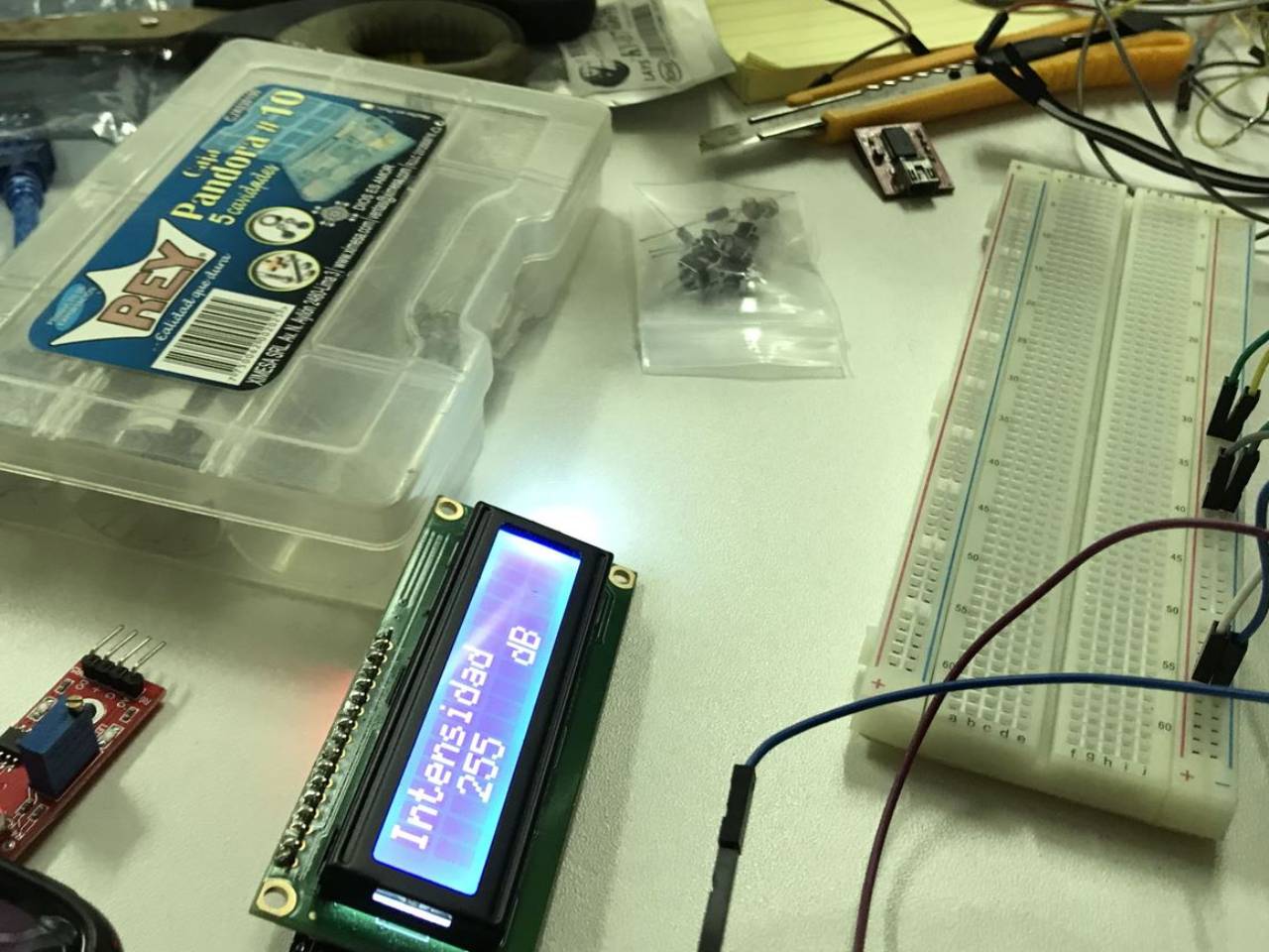
Trying with LCD I2C
Week 12 Assignment
GroupTask
This week's group work was about measuring the power consumption of an output device. This research and results were documented in detail on Mayra Ascencio's page. Here you can find the exploration I did and information about the concepts.
Basic concepts
On a board like mine with an ATtiny1614 microcontroller, voltage and amperes are key concepts to power the system and understand its consumption, and that of all sensors or actuators connected to it.
- Voltage (V) is the electrical potential difference that causes current to flow through the microcontroller and its components. The ATtiny1614 can operate over a voltage range of: 1.8V to 5.5V. This means that you can power it from a small source, such as 3.3V or 5V batteries, depending on the project. The proper voltage depends on the components, such as a servo motor, connected and whether you are using communication such as I2C or SPI, which sometimes require specific levels.
- Amperess (A) represent the amount of electrical current flowing through the board to power the microcontroller and its peripherals (sensors, LEDs, etc.). Typical power consumption of the ATtiny1614 is in the range of 1 mA to 10 mA (milliamps) when powered on and running at full speed. If the microcontroller goes into sleep mode, the power consumption can go down to a few microamperes (µA), which makes it efficient for low-power projects.
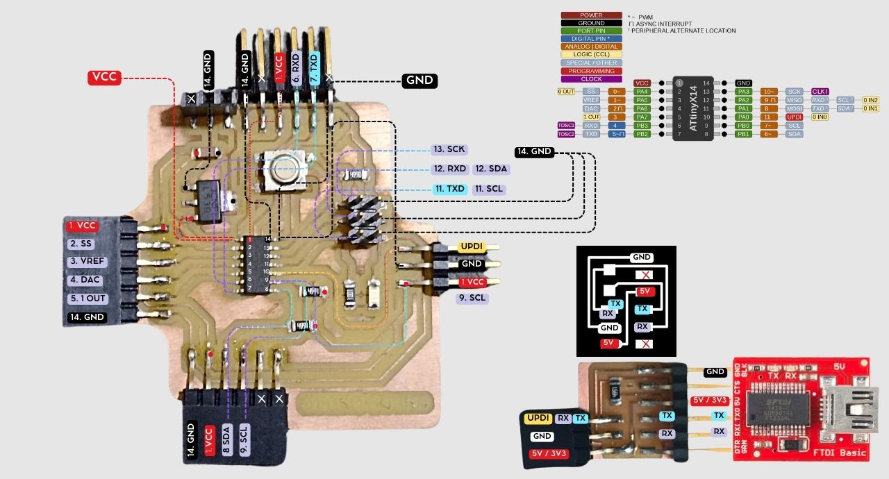
All connections on the board
Testing and measuring
“The MG996R servo dancing to the beat of the code” 💃🔧 This code is like programmed choreography for the MG996R servo, one of the strongest and most popular servo motors. Simply put, I tell the servo to move at different angles, pausing between each movement, as if it were warming up for a robotic dance. 🤖 This exercise I used below I used to test the group part as part of my experimentation.
The MG996R is a strong and precise servo, once the programming is uploaded it will move slowly from 0° to 30° to 60°, with marked pauses between each movement. When this action happens together with Mayra, we will measure the Amperes(A) and Voltage(V). This exercise was tested by both of us on her electronic board as well as on mine.
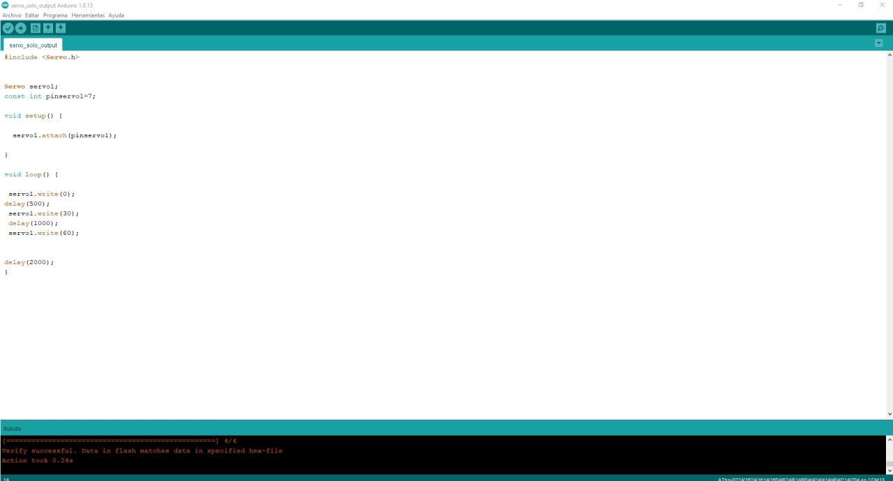
Servo code uploaded
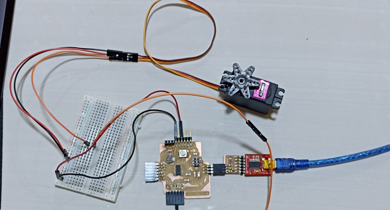
Servomotor working
First: Servomoto working
Measuring the voltage
To measure the voltage used by the MG996R servomotor while it is running, you must do so technically and safely by following these steps:
Setting up the multimeter:
- Set the multimeter to the DC voltage measurement mode (V=).
- Make sure that the measurement range covers the expected voltage (in this case, between 4.8V and 6V, which is the typical operating range of the MG996R servo motor).
- Identify the servomotor wires: Red: positive (+) (power) line. Black or brown: negative (-) (ground) line. Orange: signal line (controlled by the ATtiny1614 microcontroller).
- Place the multimeter tips parallel to the servomotor power supply:Red multimeter tip on the positive (+) line (red servo wire).Black multimeter tip on the negative (-) line (black or brown servo wire).
- With the multimeter in place, activate the servo motor and observe how the voltage varies as the servo moves.
Measuring Voltage
Measurement of current (Amperes)
To measure the amperes consumed by the MG996R servomotor while it is running, you must perform the measurement in a technical and safe manner by following these steps:
Setting up the multimeter:
- Set the multimeter to the DC current (A) measurement mode.
- If the multimeter has different current ranges (e.g. 200 mA, 10 A), select the highest range, as the MG996R can draw up to 1.5 A or more under full load.
- Connect the red tip of the multimeter to the current port (10 A) if you are not sure of the exact consumption to avoid damaging the multimeter.
- To measure current, the multimeter must be connected in series with the servomotor power circuit.
- Temporarily disconnect the red (positive) wire that powers the servomotor.
- Connect the red lead of the multimeter to the end of the positive lead coming from the power supply.
- Connect the black tip of the multimeter to the red wire from the servomotor (i.e., where the positive was originally connected).
- The black or brown wire from the servomotor (ground) remains connected normally.
- With the multimeter in series, turn on the servomotor and observe the current (amperes) reading.
- If the servomotor is under load (e.g., moving something heavy), the consumption can go up to 1.5 A or more. At idle or no load, the consumption is much lower, around 100-300 mA.
- If the consumption is too high or unstable, it may be an indication that the servomotor is strained or that the supply does not have sufficient capacity.
Measuring Amperes
IndividualTask
In this task I will connect as output device a 16x2 LCD display with blue background I2C interface to my PCB board that I previously designed and fabricated.
First try 😅
My first exercise for this task is to use a 16x2 LCD display with blue background I2C interface that allows to add a way to display project messages, the display has a low current consumption and a wide viewing angle so that it can be seen from any direction you look at it.
Main components:
- 16x2 LCD display
- My PCB board
- The LDC 16x2 display shows the message on the screen.
- Show Ottino.
- Show Move and Sound

Display LCD
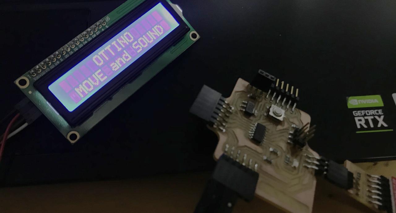
Display operating
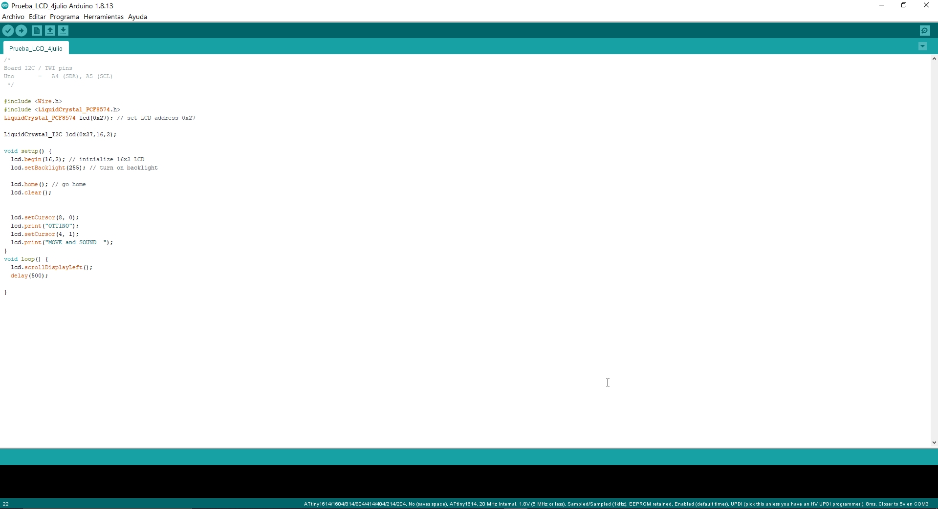
Program
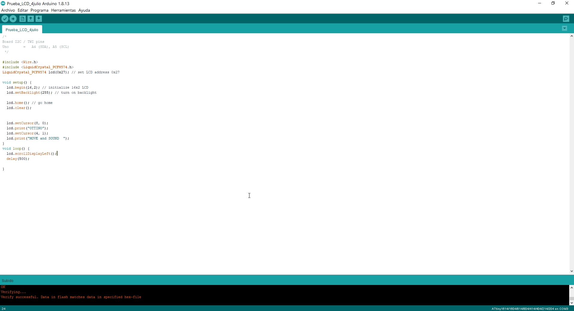
Loaded program
    #include <Wire.h>
    #include <LiquidCrystal_PCF8574.h>
    LiquidCrystal_PCF8574 lcd(0x27); // set LCD address 0x27

    void setup() {
    lcd.begin(16,2); // initialize 16x2 LCD
    lcd.setBacklight(255); // turn on backlight

    lcd.home(); // go home
    lcd.clear();


    lcd.setCursor(8, 0);
    lcd.print("OTTINO");
    lcd.setCursor(4, 1);
    lcd.print("MOVE and SOUND  ");
    }
    void loop() {
    lcd.scrollDisplayLeft();
    delay(500);

    }
Arduino IDE Code LCD display
Final result!!!
Second try 😅😅
In my second try use MG996R Servo, Metal Gear, High Torque, stable motor without anti-vibration core, metal gear, longer service life. Power supply external adapter, cable length: about 30CM. Wiring: orange: signal wire, red: positive pole, brown: negative pole.
Main components:
- MG996R Servo, Metal Gear, High Torque
- My PCB board
- The MG996R Servo Rotate angle: 0°.
- The MG996R Servo Rotate angle: 30°.
- The MG996R Servo Rotate angle: 60°.
- Back to cycle
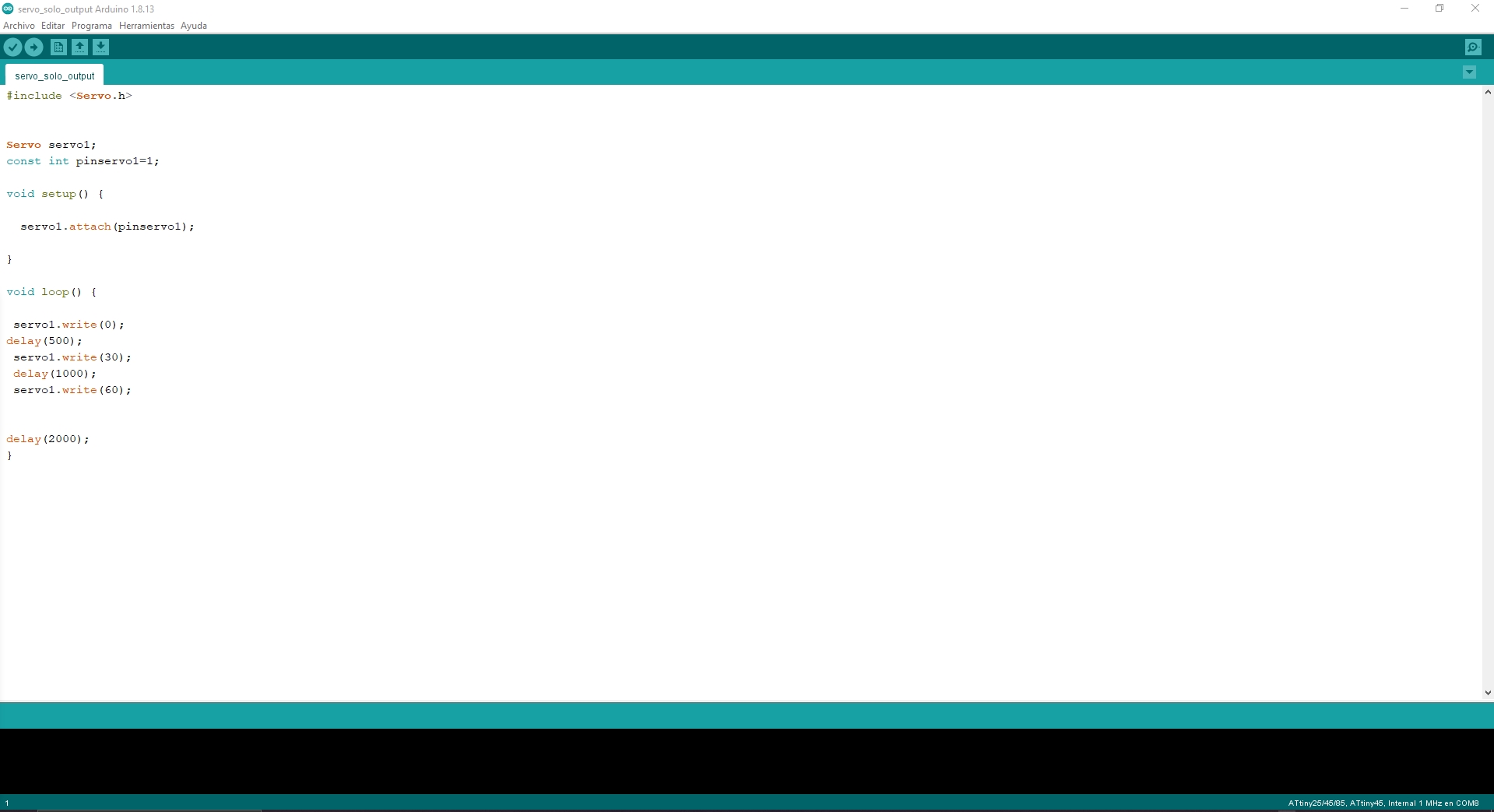
Program

Loaded program
    #include <Servo.h>


    Servo servo1;
    const int pinservo1=1;

    void setup() {

        servo1.attach(pinservo1);

    }

    void loop() {

        servo1.write(0);
    delay(500);
        servo1.write(30);
        delay(1000);
        servo1.write(60);


    delay(2000);
    }
Arduino IDE Code Servo
Final result with servomotor!
I will now develop a very similar exercise. The servo motor performs a smooth angular sweep from 0° to 180° and then returns to 0°, repeating this pattern indefinitely. Pin 8 acts as a status signal or indicator that switches between HIGH and LOW depending on the direction of servo movement:HIGH during angle increment.LOW during angle decrement.The serial monitor continuously displays the current servo angle, making it easy to diagnose and view the servo position.
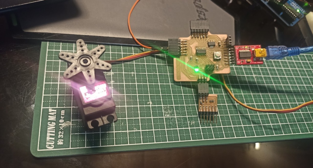
New exercise
        #include

            int angulo=0;
            Servo servo1;
            const int pinservo1=7;

            void setup() {
                Serial.begin(9600);
                servo1.attach(pinservo1);
                pinMode(8,OUTPUT);

            }

            void loop() {

            for (angulo = 0; angulo <= 180; angulo += 1) {
                digitalWrite(8,HIGH);
                servo1.write(angulo);
                Serial.print("angulo: ");
                Serial.println(angulo);
                delay(20);
                }
                for (angulo = 180; angulo >= 0; angulo -= 1) {
                digitalWrite(8,LOW);
                servo1.write(angulo);
                Serial.print("angulo: ");
                Serial.println(angulo);
            delay(20);
                }

            }
Arduino IDE Code Servo with Monitor Serie
Servomotor with monitor serie!
Servomotor with monitor serie!
AboutLearning
- I learned to use libraries such as LiquidCrystal_PCF8574 and Servo to facilitate communication and control. This is essential for developing more complex projects that include physical interfaces and motion.
- With the LCD, I learned to work with I2C communication, setting the device address and controlling parameters such as backlight brightness. This knowledge is essential for working with devices that rely on standard communication protocols in embedded systems.
- In the case of the servo motor, I learned to control its position using the Servo library, adjusting specific angles and managing delay times to create controlled movements. This is key to implement movements in robotic projects or automated systems.
My Veredictfrom what I learned
- Thanks to the available servo libraries and code, controlling a servo motor is as simple as saying, “Move at 90 degrees and wait!” I can set specific angles without breaking my head, making the movements smooth and precise.
- I learned that the outputs are the key to showing the world what the microcontroller “thinks”. With the LCD, I was able to translate invisible data such as light levels or sound into visual and understandable information. It's like giving the microcontroller a voice so that it not only processes, but also expresses itself! 📢
- The most interesting thing was to understand how the outputs turn internal signals and calculations into something real and tangible. The outputs are not just the “end of the code”, they are the proof that it all works! ✨