12. Output devices
Assignments :
- Add an output device to a microcontroller board you’ve designed and program it to do something
- Described your design and fabrication process using words/images/screenshots, or linked to previous examples.
- Explained the programming process/es you used and how the microcontroller datasheet helped you.
- Outlined problems and how you fixed them
- Included original design files and code
Project :
For this assignment I choose to work DC motor, vacuum pump, Servo Motor and electrovalve. During week 7 “Electronic design”, I’ve made a PCB with some input and output on it. I can quickly test a motor and a servomotor. So, first, I will use the board I did week 7 to test them, and after that I will design a new board so I can test another microcontroller and add more output.
The PCB :
Motors and eletrovalve
During week 7, I add to my board a circuit with a mosfet, so I can test some output like motors or electrovalve. The circuit is the following :
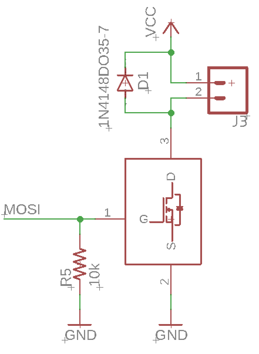
With this kind of simple circuit, you can only drive your motor in one sens. But it’s very sufficient for me and my project because :
- For my final project, the motor will always spin in the same direction.
- For the vacuum pump, there is no direction for the motor.
- For the EV, it will just be ON or OFF, so a simple mosfet is sufficient.
Concerning the mosfet, I use a version of about 1A. It’s good for me because the DC motor draw a few mA, the vacuum pump 300mA and the EV, 500mA.
Talking about the actuators, here is what I want to use :
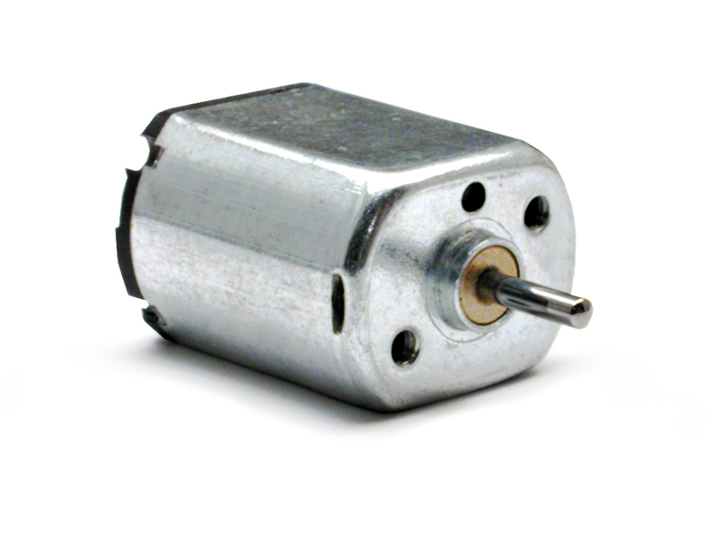
- Motor : Mabuchi FF-030
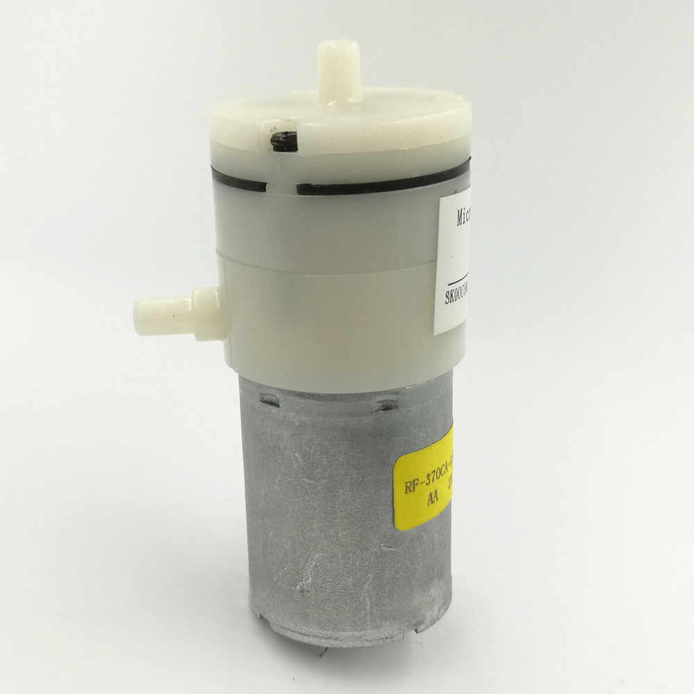
- Vacuum pump : 370 miniature vacuum pumps
- Electrovalve
| Motor | Pump | Electrovalve |
|---|---|---|
 |
 |
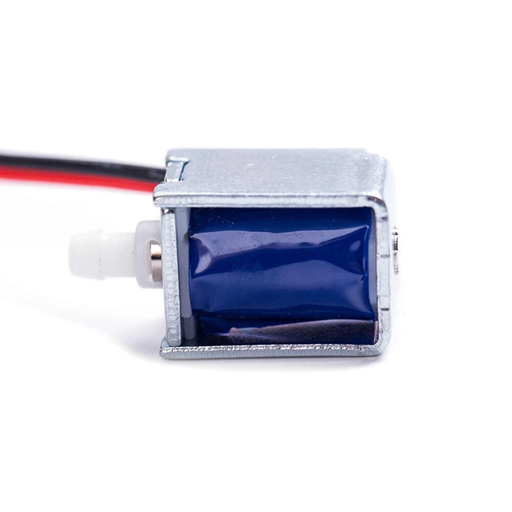 |
The electrovalve is a simple solenoid , so I can be drived like a motor.
Note
You can see that I included a flyback diode on my circuit. The flyback diode is used to eliminate flyback when driving an inductor. The flyback, “is the sudden voltage spike seen across an inductive load when its supply current is suddenly reduced or interrupted.” Wikipedia.
Always include a flyback diode when you drive inductor.
Servomotor :
I also included a 3 pin connector on this board so I can plug an input like a digital or analog sensor, but also an output like a servomotor.

A servomotor is a specific actuator which include :
- A motor
- Gear to reduce speed and increase torque
- A potentiometer to have a closed-loop regulation on the angular position
- A PCB which control the motor un function of the order received and the position read by the potentiometer
So, the servomotor will move to a position and will try to keep this position.
The servomotor I will use is RC standard servomotor. This kind of servomotor received its position order on its signal wire ( orange or white ). This signal is a 50hz signal with a time coding modulation.
Note
Some months ago, I’ve two youtube Video about servomotors. They are in french but I put them below as it explain how servomotors works and how the signal is interpreted. Also, I work on english subtitles 
The PCB
As explained before, this week I’ve used the previous board designed during week 7 “Electronic design”. You can have more informations about it following the link on the left side.
Just as a remember :
| The board | The schematic |
|---|---|
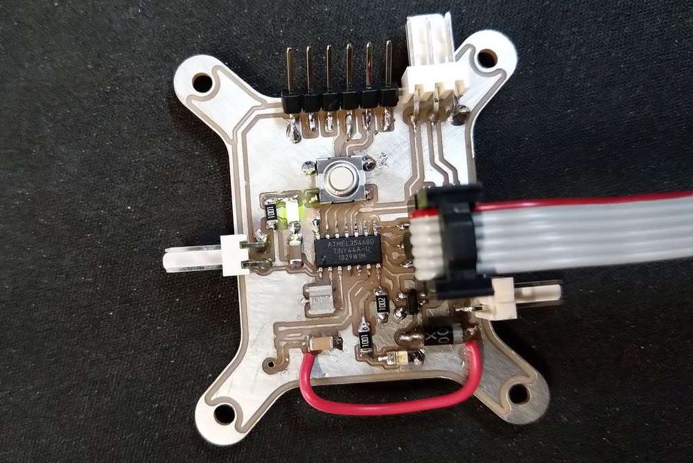 |
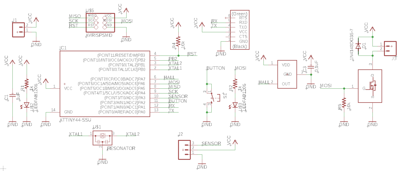 |
I use a ATTiny44 for this board. SpenceKonde made a great pin mapping cheat sheet for the attiny44 on GitHub as you can see below :
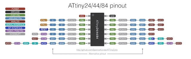
As I didn’t manage to make my board working with PlatformIO for the moment, I will use C++ with Arduino for the moment. So, In that condition, the pin mapping for my board is the following :
| Function | Pin |
|---|---|
| Button | 2 |
| External Sensor | 3 ou A3 |
| Hall Sensor | A7 |
| Mosfet ( Motor ) | 6 ( PWM ) |
| Led | 6 ( PWM ) |
| RX | 0 |
| RX | 1 |
Software
Testing the mosfet
As the MOSFET is on the same pin than a LED, the code is very similar than for the Blink LED test. I will just saturate the mosfet so 5V will go directly to the motor.
const int MOTOR = 6 ;

void setup()
{
  pinMode(MOTOR, OUTPUT);
}

void loop()
{
  digitalWrite(MOTOR, HIGH);
  delay(1000);
  digitalWrite(MOTOR, LOW);
  delay(1000);
}
Results and conclusions :
I know that this works because I already test it during week 07. As you can see on the video below, the motor is turning on only one direction, and at a frequency of 1hz.
Change the speed of the motor
To change the speed of the motor, I will use the PWM principle to modulate the time I saturate the mosfet so the average voltage to the motor in the output of the mosfet will vary from 0 to 5V (the supply voltage). To do that, I will use a new command analogWrite(pin,0 to 255). This command will allow me to generate a pwm signal on the pin as a steady square wave of the specified duty cycle until the next call to analogWrite(). More informations here..
To test that, I will generate an acceleration of the motor, a constant speed and then a deceleration and a stop. I will do that with two for command by incrementing the value of the PWM in a first time and then decrementing it.
const int MOTOR = 6 ;
int maxSpeed = 220;

void setup()
{
  pinMode(MOTOR, OUTPUT);
}
void loop()
{
  //Acceleration
  for(int i=0;i<=maxSpeed;i++)
  {
    analogWrite(MOTOR, i);
    delay(10);
  }

  delay(2000); //constant speed during few seconds

  //Deceleration
  for(int i=maxSpeed;i>0;i--)
  {
    analogWrite(MOTOR, i);
    delay(10);
  }

  delay(2000); //stop during few seconds
}
Results and conclusions :
Regulate the speed
For my final project, I will need to regulate the speed of the motor using the hall sensor. On the previous week11, I already made a code to read the hall sensor and determine the time between two reading. Now I will use this code and the previous code to try to regulate the speed of the motor.
The principles is simple :
- I will determine a desired speed ( so a time to achieved )
- If the time is too long ( low speed ) –> increase the speed of the motor
- If the time is too low ( high speed ) –> decrease the speed of the motor
It’s basically a regulation method. To do this I write the code below and test it withe the serial monitor only the first time :
#include <SoftwareSerial.h>
SoftwareSerial mySerial(0, 1); // RX, TX

int lastError = 0;
const int MOTOR = 6 ;
int maxSpeed = 220;
const int hallSensor = 7;
unsigned long elapsedTime = 0;
bool control = 0;
bool debug = false;
int orderTime = 1000; // desired time between two tick in milliseconds
int motorSpeed = 0;

void setup()
{
  mySerial.begin(4800);
  pinMode(hallSensor,INPUT_PULLUP);
  pinMode(MOTOR, OUTPUT);
  debug=true;

}

void loop() {

  //Find the elapsedTime :
  bool sensorState = digitalRead(hallSensor);
  if ( sensorState && control )
  {
    elapsedTime = millis();
    control = false;
  }
  if ( !sensorState && !control )
  {
    elapsedTime = millis() - elapsedTime;
    control = true;
    int error = elapsedTime - orderTime;

    if (error > 300) motorSpeed += 10;
    else if (error < -300) motorSpeed -= 10;

    // constrain the speed of the motor
    if (motorSpeed>=maxSpeed) motorSpeed = maxSpeed;
    if (motorSpeed<=0) motorSpeed = 0;

    analogWrite(MOTOR,motorSpeed);

    if (debug)
    {
      mySerial.print("Time :");
      mySerial.print(elapsedTime);
      mySerial.print(" mS");
      mySerial.print(" | error :");
      mySerial.print(error);
      mySerial.print(" | motor speed :");
      mySerial.println(motorSpeed);
    }
  }
}
After that’s working correctly, I turn off the debug mode and plug my motor and my battery to test the same thing with just the motor, and make some change on the code to make it working with the motor speed and clean a litle bit my code.
#include <SoftwareSerial.h>
SoftwareSerial mySerial(0, 1); // RX, TX

const int orderTime = 500;    // Desired time between two tick in milliseconds
const int errorMargin = 100;  // Margin of the error
const int maxSpeed = 220;     // The max speed allow on the motor

const int hallSensor = 7;     // Pin of the hall sensor
const int motor = 6 ;         // Pin of the motor

unsigned long elapsedTime = 0;      // Time between to tick
bool control = 0, debug = false;    // Control boolean

int motorSpeed = 100;         //Set a speed at the beginning.

void setup()
{
  mySerial.begin(4800);               // Initialisation f the serial link
  pinMode(hallSensor,INPUT_PULLUP);   // Initialisation of the hall sensor pin
  pinMode(motor, OUTPUT);             // Initialisation of the motor pin
  debug=false;                        // Set to true or False whenever you want to have the serial debug
}

void loop()
{
  bool sensorState = digitalRead(hallSensor);
  if ( sensorState && control )
  {
    elapsedTime = millis();
    control = false;
  }
  if ( !sensorState && !control )
  {
    elapsedTime = millis() - elapsedTime;
    control = true;
    int error = elapsedTime - orderTime;

    if (error > errorMargin) motorSpeed += 10;
    else if (error < -errorMargin) motorSpeed -= 10;

    // constrain the speed of the motor
    if (motorSpeed>=maxSpeed) motorSpeed = maxSpeed;
    if (motorSpeed<=0) motorSpeed = 0;

    analogWrite(motor,motorSpeed);

    if (debug)
    {
      mySerial.print("Time :");
      mySerial.print(elapsedTime);
      mySerial.print(" mS");
      mySerial.print(" | error :");
      mySerial.print(error);
      mySerial.print(" | motor speed :");
      mySerial.println(motorSpeed);
    }
  }
}
Have fun with a vaccum pump
I’ve got a vacuum pump and, as it’s basically a DC motor, I can also control it with my board. I use the code below and you can see the results in the video :
const int motor = 6 ;         // Pin of the motor
int motorSpeed = 200;

void setup()
{
  pinMode(motor, OUTPUT);             // Initialisation of the motor pin
}

void loop()
{
  analogWrite(motor, motorSpeed);
  delay(2000);
  analogWrite(motor, 0);
  delay(2000);
}
The test of the pump :
Trying to vacuum a plastic box
Servomotor
For the driving of the servomotor, I need to produce a 50hz signal and a time code modulation, with a high signal between 1 and 2ms.
To do that, I could use the interrupt function of the attiny. But I was thinking about doing it without interrupt … So, to do that, I created some functions :
void servoWrite(int angle) : it takes the angle and convert it so we have the duration of the pulsation we send to the servomotors
void servoWrite(int angle)
{
  timeServo = map(angle,0,180,1000,2000) ;
}
void updateServo() : it generate the signal for the servomotor
void updateServo()
{
  digitalWrite(pinServo,HIGH);
  delayMicroseconds(timeServo);
  digitalWrite(pinServo,LOW);
  delay(21);
}
void waitServo(int waitTime) : it’s a function that replace the delay() function. It wait a given time in milliseconds, and update the servomotor position during this time.
void waitServo(int waitTime)
{
  long initTime = millis();
  while((millis()-initTime )<= waitTime)
  {
    updateServo();
  }
}
So, with this simple function you just have to add the following declarations at the beginning of your code :
int pinServo = 3;
int timeServo = 1500;

void servoWrite(int angle);
void updateServo();
void waitServo(int waitTime);
And you can write a main code like this :
void setup()
{
  pinMode(pinServo, OUTPUT);
}

void loop()
{
  servoWrite(0);
  waitServo(2000);
  servoWrite(90);
  waitServo(2000);
  servoWrite(180);
  waitServo(2000);
  servoWrite(90);
  waitServo(2000);
}
And it will do this :
By changing the loop() section, you can do better variations :
void loop()
{
  //Acceleration
  for(int i=0;i<=180;i+=2)
  {
    servoWrite(i);
    updateServo();
  }
  //Deceleration
  for(int i=180;i>0;i-=2)
  {
    servoWrite(i);
    updateServo();
  }
}
Useful links
By doing some research about Attiny family, I found this interesting link with all the attiny family and comparison between every device.