18. Wildcard - Robotics
1 - Introduction
For this week, I would like to document the work I’ve done for the robot of the french cup of robotic. Inside this robots, we have decided this year to use two micro-controllers that will be linked using an I2C bus. The roles of the two micro-controllers will be the following :
- uC 1 - Master - Strategy of the match / managing the actuators / print informations on the LCD
- uC 2 - Slave - Will have to manage all the robot movements
As the micro-controllers will have to manage a lot of informations in a same time, very quickly, and will have to make some math for the movements of the robots for example, we would like to have uC very powerful so we can use them for the next years without changing them every time to save development time and cost for our future robots.
As the electronic responsible of the team, I’m in charge of the production of the PCB of the robot and also of the embedded code. So, my solution is to use :
- A teensy 3.5 for the uC 1 ( ARM micro-controllers )
- A teensy 3.2 for the uC 2
- A I2C bus to link them together
Also, I’ve made the choice to not producing the final PCB myself but ask to a company to to it for me. It assure me robustness for the competition, and as I will have to produce two time the PCB for the two same robots, It will be easiest for me.
I choose to use the Seeeds Fusion services to produce my board and I will soldered the components myself.
2 - PCB Design
Disclaimer
The board is more complex than a simple I2C connection. So I will focus my documentation here on the communication parts. I will use this board also for my final project because it will communicate with the main board of the robot to send the position of the opposing robots.
2.1 Communication part
To design my board, I use the Eagle software. For the communication parts, I decided to directly put the two uC on the same board and connect the SDA and SCL pin of each teensy together.
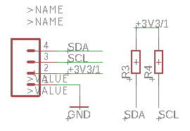
I also added a connector so I can add some other board to the I2C bus. The two lines SDA and SCL are connected to the 3.3V using a pull-up resistor of about 4.9kOhms.
On the external connector, I embedded the ground line and also the 3.3V supply.
| The teensy schema | the communication I2C side |
|---|---|
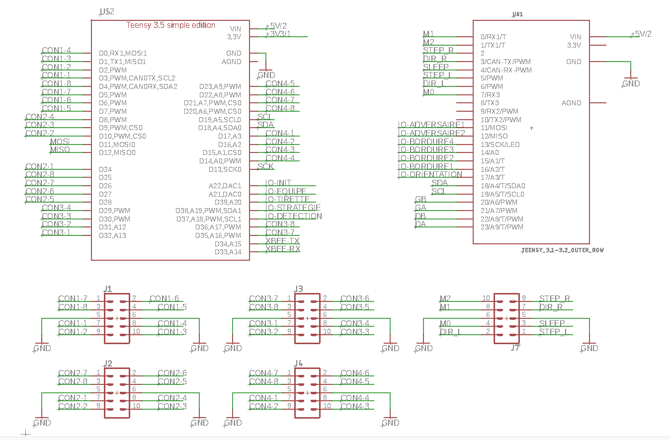 |
 |
It will not be covered here, but I also added a serial connector to add in the futur a wireless communication between our two robots using Xbee standard.
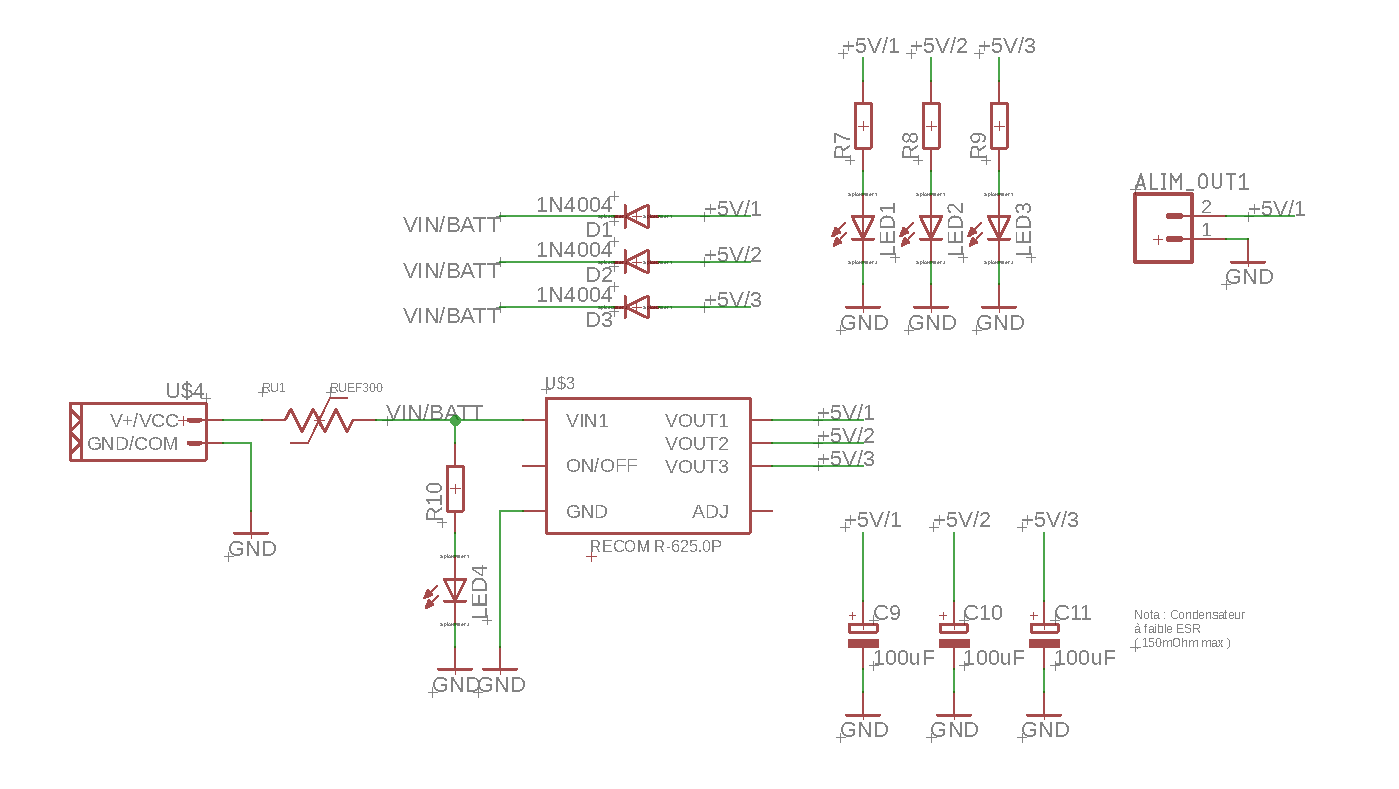
2.2 Supply part
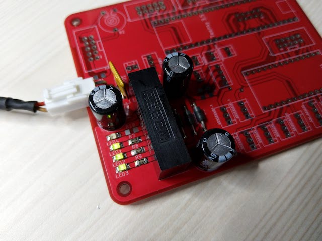
As the robot is supplied by a lipo Battery 6S (22,2V), I need to regulate the voltage to 5V for th uC and the sensor of the robot. To do that, I use a regulator from Recom which is very interesting because it could regulate 3 outputs to 5V 2A without heating and with a high efficency. Moreover, it is fully integrated and very easy to use. the version is the R625.0P
On the regulation part, I have also added some LED to indicate if the output is correctly regulated and if the board is powered by the battery.
2.3 Routing
to route my board, I directly use a double side file, because with the production by Seeed, I hav not the same limitation. Also, A lot of components and are through hole version. That’s due to the fact that our robotic team has a lot of stock of thought hole connectors, and also, it makes it easier for me to route the double side signal and made a compact board.
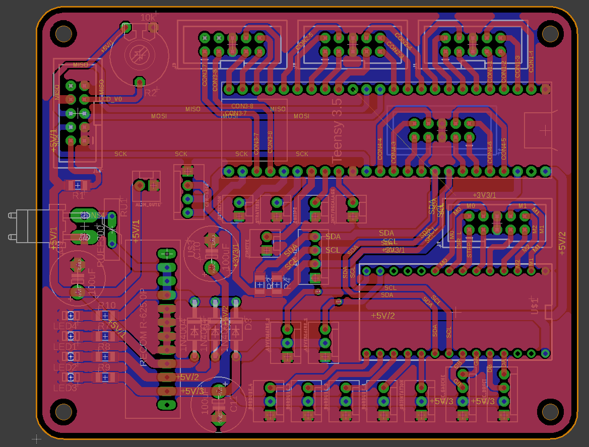
I also simulated my board on fusion 360 so I can test the implementation of it into my robot.
| The 3D Board | The board inside the robot |
|---|---|
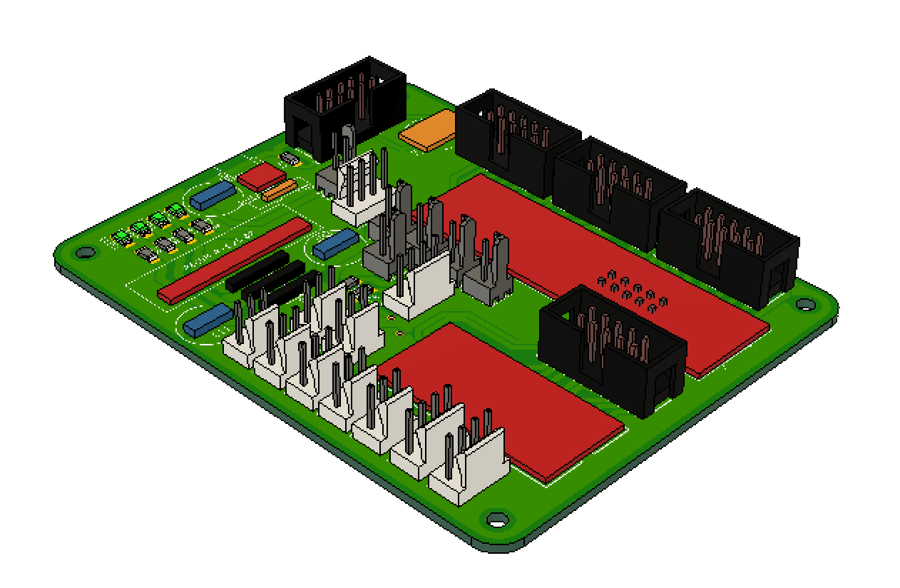 |
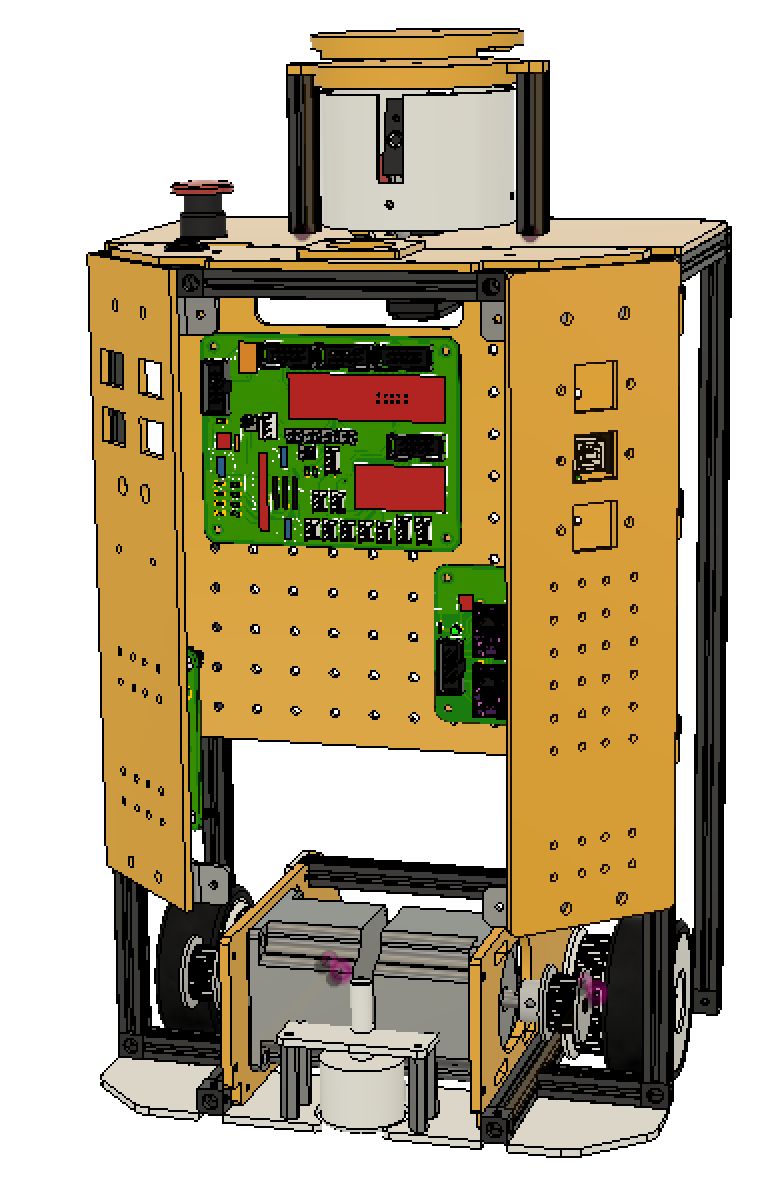 |
3 - PCB production
3.1 - Ordering the PCB
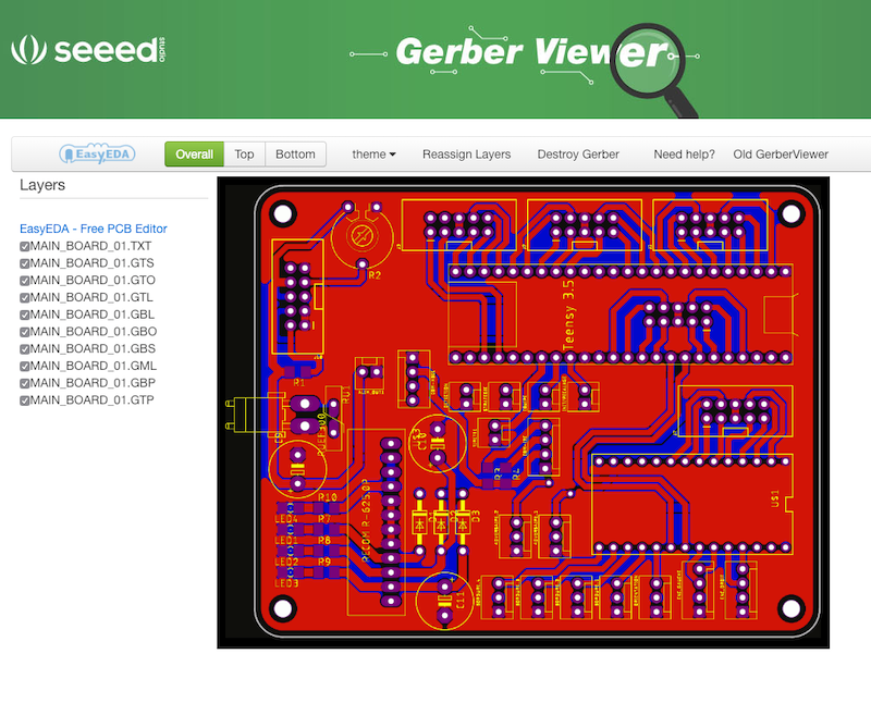
So, as explain before, I tested the production of my board by seeed services. In the new version of Eagle, there is directly a may to export the project with the seeed standard, so it’s really easy to make for production. You just have to go to the CAM Processor option, And select “System Exmaples > Third Party > Seeed Fusion > SeeedFusion_2_layer.cam”.
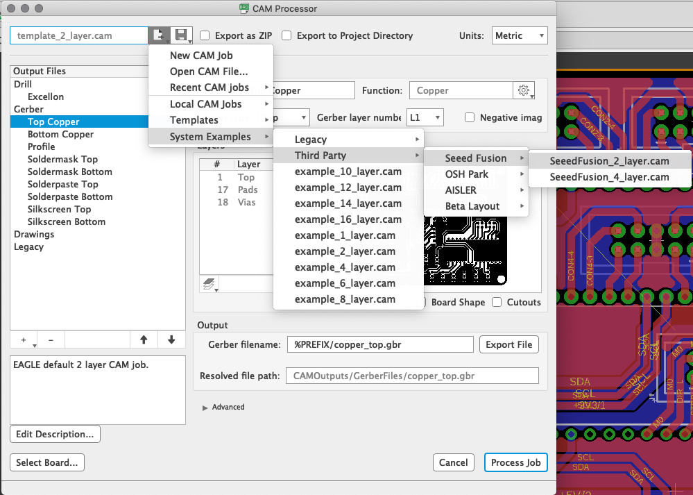
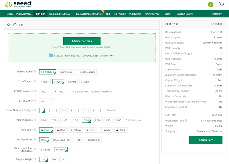
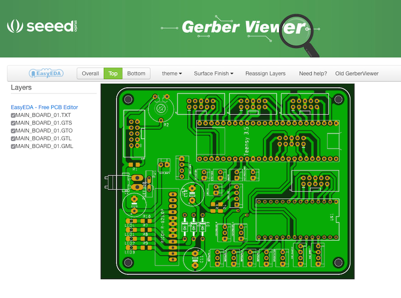
Eagle will generate all the files you need, and you will just have to go on the seeed fusion site and import your file to have an online quotation. You can also verify your gerber file, and modify some option of your board.
| Import and have an online quotation | Verify your gerber file | Verify your gerber file |
|---|---|---|
 |
 |
 |
And that’s all. You can order, pay, and wait for your PCB  .
.
You can find my production file below :
3.1 - Soldering the PCB
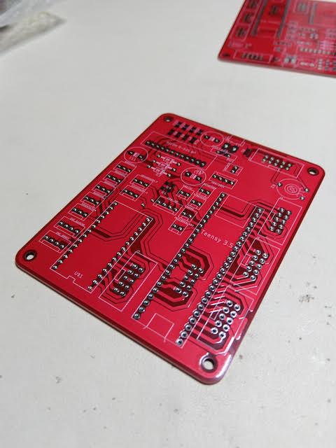
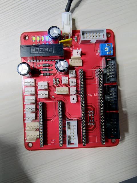
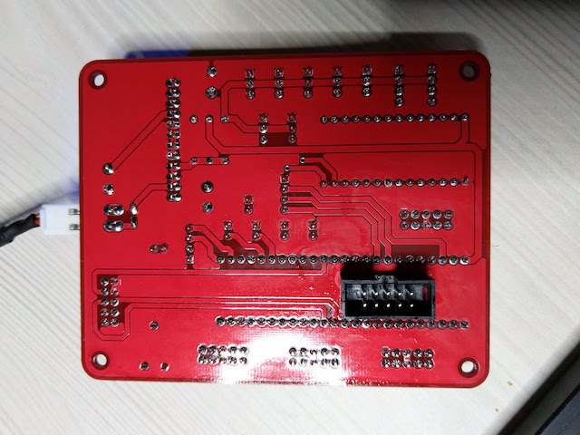
The soldering of the board was very easy. The PCB I received was so clean and well done for the price ! I first soldered the supply part to test the regulation. And after that I soldered all the other components.
| The supply soldering | All the components soldered | The back of the PCB |
|---|---|---|
 |
 |
 |
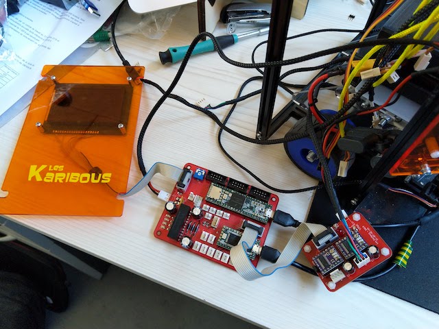
After that, I put the two micro-controller on the board and also plug the LCD screen to begin my test and the coding of the robot. I also soldered and plug the motor PCB (I didn’t explain it here but it’s a simple shield for two stepper drivers).
4 - Programming
As the code is very complex and big, I will just present some function that can be interesting for other projects.
For further informations, you can directly download the code following the links below :
4.1 - Programming the LCD screen and Human interface
Human interface
For the human interface, we have several buttons and something called the “tirette” in french that allow the robot to begin it’s match. Ti update the LCD and the parameters of the robots, we first need to get the states of every interface input. to do that we have the function void buttonIHM() :
void bouttonIHM()
{
  detection = digitalRead(pinDetection) ;
  tirette   = digitalRead(pinTirette)   ;
  strategie = digitalRead(pinStrategie) ;
  typeRobot = digitalRead(pinRobot) ;

  if(analogRead(pinEquipe)>10) equipe = false ;
  else equipe = true ;

  if(analogRead(pinCheck)>10)
  {
    delay(250);
    if(analogRead(pinCheck)>10) check = true ;
  }
  else check = false ;

  if(!check) initRobot();
}
LCD Screen
For the screen, it’s a LCD 128x64 screen ST7920. It’s a graphical LCD which can be use with different kind of communication like :
- I2C
- Parrallels
- SPI
As the I2C is use to transfer orders between the two uC and as this transfer are very important, I do not wanted to overcharged this bus. The parallel solution is very quick but pin consuming. So, I decided to use SPI link.
As it’s a graphical screen, it can be very complicated to code all the function by hand. Hopefully, there is a very nice library developed by olikraus called u8g2. It’s a very powerfull library for all kind of LCD screen and very nicely written.
So, I made several functions with this library, and the most interesting are :
void u8g2_menu_avant_match()for the menu before the start of the matchvoid u8g2_menu_pendant_match()for the menu during the match
The code are below. As you can see, the library make it very easy to use, and the video below show you how beautiful it can be. The number of fonts available for the screen is totally madness ! 
void u8g2_menu_avant_match() {
  const int ligneDebut = 10;
  const int colonne1 = 14;
  const int colonne2 = 70;

  u8g2.clearBuffer();
  u8g2_prepare();

  u8g2.setFont(u8g2_font_4x6_tf);
  // Affichages des titres :
  u8g2.drawStr( colonne1, ligneDebut,    "      EQUIPE");
  u8g2.drawStr( colonne1, ligneDebut+10, "   EVITEMENT");
  u8g2.drawStr( colonne1, ligneDebut+20, "       ROBOT");
  u8g2.drawStr( colonne1, ligneDebut+30, "ETAT TIRETTE");
  u8g2.drawStr( colonne1, ligneDebut+40, "   STRATEGIE");
  // Ligne de séparation
  u8g2.drawBox(colonne2-4,ligneDebut,1,ligneDebut+37);

  // Etat equipe :
  u8g2.setCursor(colonne2,ligneDebut);
  if ( equipe == EQUIPE_JAUNE ) u8g2.print("JAUNE");
  else u8g2.print("VIOLET");
  // Etat detection:
  u8g2.setCursor(colonne2,ligneDebut+10);
  if ( detection ) u8g2.print("SIMPLE");
  else u8g2.print("COMPLET");
  // Etat type de robot :
  u8g2.setCursor(colonne2,ligneDebut+20);
  if ( typeRobot == ROBOT_PRIMAIRE ) u8g2.print("PRIMAIRE");
  else u8g2.print("SECONDAIRE");
  // Etat tirette :
  u8g2.setCursor(colonne2,ligneDebut+30);
  if ( tirette ) u8g2.print("ATTENTE");
  else u8g2.print("OK");
  // Etat strategie :
  u8g2.setCursor(colonne2,ligneDebut+40);
  if ( strategie ) u8g2.print("HOMOLOGATION");
  else u8g2.print("MATCH");

  u8g2.sendBuffer();
}
void u8g2_menu_pendant_match() {
    u8g2.clearBuffer();
    u8g2_prepare();
  u8g2.setFont(u8g2_font_inr42_mn);
  u8g2.setCursor(8, 9);
  u8g2.print(score);
  u8g2.setFont(u8g2_font_4x6_tf);
  u8g2.drawStr( 0, 0, "Score:");
  u8g2.drawStr( 68, 0, "Temps:      sec");
  u8g2.setCursor(93, 0);
  u8g2.print(tempsRestant);
  u8g2.drawStr( 105, 57, "points");
  u8g2.drawStr( 0, 57, "NOK:");
  u8g2.setCursor(20, 57);
  u8g2.print(nbrBadCRC);
    u8g2.sendBuffer();
}
4.2 - Programming the network
For the network, as I explained before, I used I2C between the two micro-controllers. As the informations between them are very important, I have implementer a CRC protocole so I can verify each message and re-send them if there are not good or if there were a link issue. All the CRC issue are reported to the master and print on the screen inside the function void u8g2_menu_pendant_match() described just before :
u8g2.drawStr( 0, 57, "NOK:");
u8g2.setCursor(20, 57);
u8g2.print(nbrBadCRC);
To do that, on the master side we have the following code (which is similar to what I did during week14 with a serial network) :
The function void sendNavigation(byte fonction, int rot, int dist) send to the navigation side the next coordinates to achieve with some parameters.
void sendNavigation(byte fonction, int rot, int dist)
{
    if ( equipe == EQUIPE_VIOLET ) rot = -rot ;
    // Stockage des valeurs à envoyer dans le buffer
    bufNavRelatif[0]=fonction;
    bufNavRelatif[1]=rot >> 8;
    bufNavRelatif[2]=rot & 255;
    bufNavRelatif[3]=dist >> 8;
    bufNavRelatif[4]=dist & 255;
    // Calcul du CRC
    crcNavRelatif = CRC8.smbus(bufNavRelatif, sizeof(bufNavRelatif));
    //Serial.println(crcNavRelatif);
    // Envoi des données
    Wire.beginTransmission(CARTE_DEPLACEMENT);
    for(int i=0;i<=4;i++)
    {
        Wire.write(bufNavRelatif[i]);
    }
    Wire.write(crcNavRelatif);
    Wire.endTransmission();
}
The function int askNavigation() ask from the navigation side if the movement is achieved or if there were an issue on the CRC protocol. If yes, we can re-send the last position.
int askNavigation()
{
  int etatNavigation ;
  char reponseNavigation ;
  Wire.requestFrom(CARTE_DEPLACEMENT, 1);
  while(Wire.available())
  {
    reponseNavigation = Wire.read();
  }
  // Serial.print("repNav:");
  // Serial.println(reponseNavigation);
  if (reponseNavigation=='N') etatNavigation = RECU ;
  else if (reponseNavigation=='O') etatNavigation = TERMINEE ;
  else if (reponseNavigation=='E') etatNavigation = ERRONEE ;
  else reponseNavigation = BIZARRE ;
    return etatNavigation;
}
On the navigation side, we have the several functions :
the void receiveEvent(int howMany) which is called when a new order is received.
void receiveEvent(int howMany)
{
    if(howMany == 6)
    {
        // Si un déplacement relatif est demandé
        // On receptionne les données
        for (int i=0;i<=5;i++)
        {
            bufNavRelatif[i]=Wire.read();
        }

        // On calcul le CRC
        crcNavRelatif = CRC8.smbus(bufNavRelatif, sizeof(bufNavRelatif)-1); //On enleve le CRC
        Serial.println(crcNavRelatif);
        // On regarde si le CRC calculé correspond à celui envoyé
        if (crcNavRelatif==bufNavRelatif[sizeof(bufNavRelatif)-1])
        {
            // CRC ok
            // On traite les données
            fonction = bufNavRelatif[0];
            relativeRequest[0]= bufNavRelatif[1] << 8 | bufNavRelatif[2];
            relativeRequest[1]= bufNavRelatif[3] << 8 | bufNavRelatif[4];
            optionAdversaire = bitRead(fonction, 0);
            optionRecalage = bitRead(fonction, 1);
            optionRalentit = bitRead(fonction,2);
            // On indique qu'une nouvelle position est disponible
            newPos = DISPONIBLE;
        }
        else
        {
            // CRC nok - la donnée est erronée
            // On indique que la prochaine position est erronée pour en renvois eventuel
            newPos = ERRONEE;
        }
    }
}
The void requestEvent() function which is called when a new information is asked from the master.
void requestEvent()
{

    if ( etatAvance == FINI && etatRotation == FINI && newPos == VALIDEE && !etatABS && !etatLastRot)
  {
    // Mouvement terminé
        Wire.write('O');
    }
    else if (newPos == ERRONEE)
    {
    // Commande non validé
        Wire.write('E');
    }
    else
    {
    // Mouvement non terminé
        Wire.write('N');
    }
}
5 - Testing
5.1 - Testing lcd screen
5.2 - Testing movements
6 - Conclusion and results
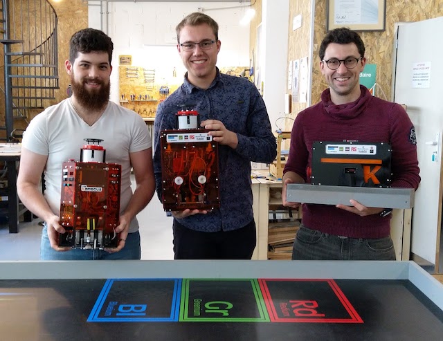
The conclusion is that it works very very well !! We didn’t had any issue due to my electronic or to the network between the two uc. The two robots worked perfectly and we managed to finish at the 20th places on 140 participants ! The better score we get in 9 years !!
If you want more informations, you can go to the website of my team Les Karibous.
And after the cup, we did some other tests and we managed to achieved very high speed with our robot … But it also mean that we have to better calibrate it !!