7. Electronics design
Assignments
- Redraw the echo hello-world board,
- Add (at least) a button and LED (with current-limiting resistor)
- Check the design rules, make it, and test it
Eagle
Eagle is an electronic CAD software use to design PCB. It’s a professional software but you can use it freely with some restrictions.
Importing the Fab Library
To redraw the board and add features, I’ve used the Eagle library for the FabLab with all the components of the inventory. You can find it here : Eagle library
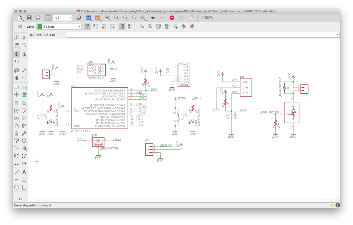
Design the Schematic
First, I’ve added the different parts for the original Hello-world board :
- ATTiny44
- LED
- Resistors
- Connectors
- Button
- Resonator
- Capacitor
Add also added some symbols like :
- VCC
- GND
I first tidied the schematic and connect all the alimentation signal. I’ve also added a Led to know if my board is well supplied. After that, I added some labels to help me during the design process and renamed them.
I’ve also changed the value of the components ( resistors for example )
After that, I decided to add some components to make some test for my final project, such as :
- Supply connector
- 3 pin sensor connector
- Analog Hall sensor
- A mosfet to drive a motor
For the moment I will not connect the different things I added to the board. I will try to make my board, tidy the placement of my components and see where is the best place for them and the simple way to connect them to the AtTiny.
Routing the board
I’ve created the board using the schematic. After that, I’ve moved the components to tidy the board and try to assemble the components by group.
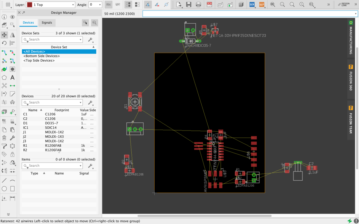
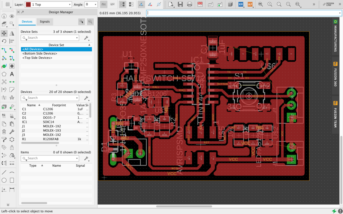
Before routing, I’ve opened the DRC menu and change the parameters so I can use a 1/64 mill bit every where. I’ve placed the added components and wire it to the more versatile pin of the Attiny.
Because I will need the timer1 for the PWM for my motor, I will use the same pin used for MOSI for the PWM motor and for the LED. So I can test the functionalities of the Mosfet directly with the LED.
To help me during the routing process, I’ve placed a Ground plane. I’ve also modified the hall sensor and use the one in the Fab inventory.
Here you can find the source file.
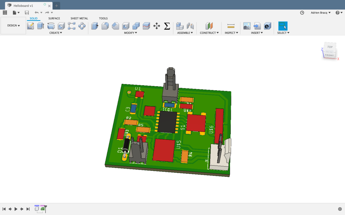
3D PCB with Fusion
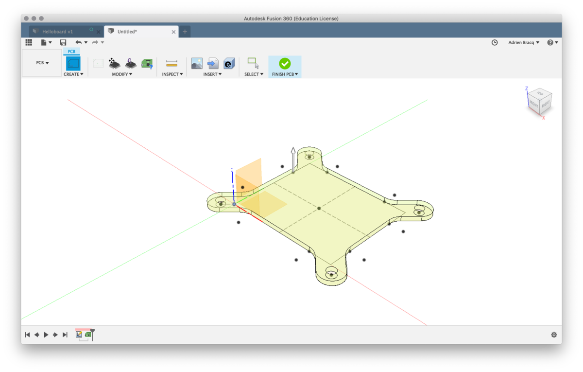
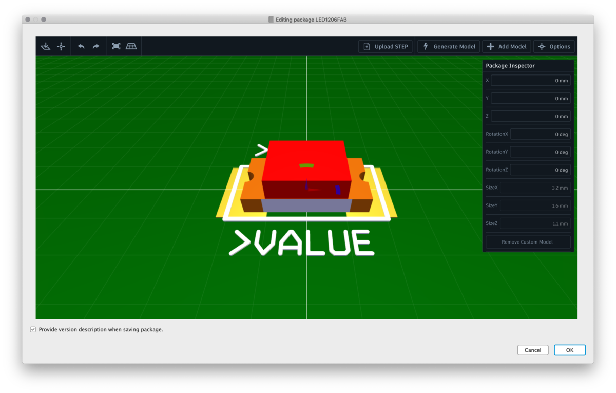
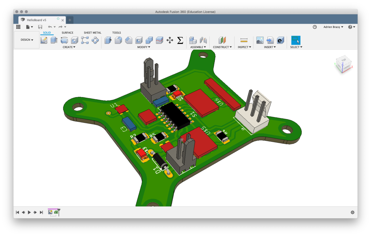
I’ve also experimented with the link between fusion360 and Eagle. I’ve made a custom outline of the board and imported some 3D components into the FabLibrary.
| 3D of my first version | custom outline | Creating/importing new 3D components |
|---|---|---|
 |
 |
 |
Using two side PCB
After a long time trying to route the board with only one face, I decided to move and redraw all the board because I didn’t manage to find a way to do it. So The idea was to route the board with a two-side version and try to do that with the OtherMill
Milling the board
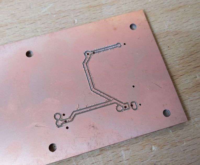
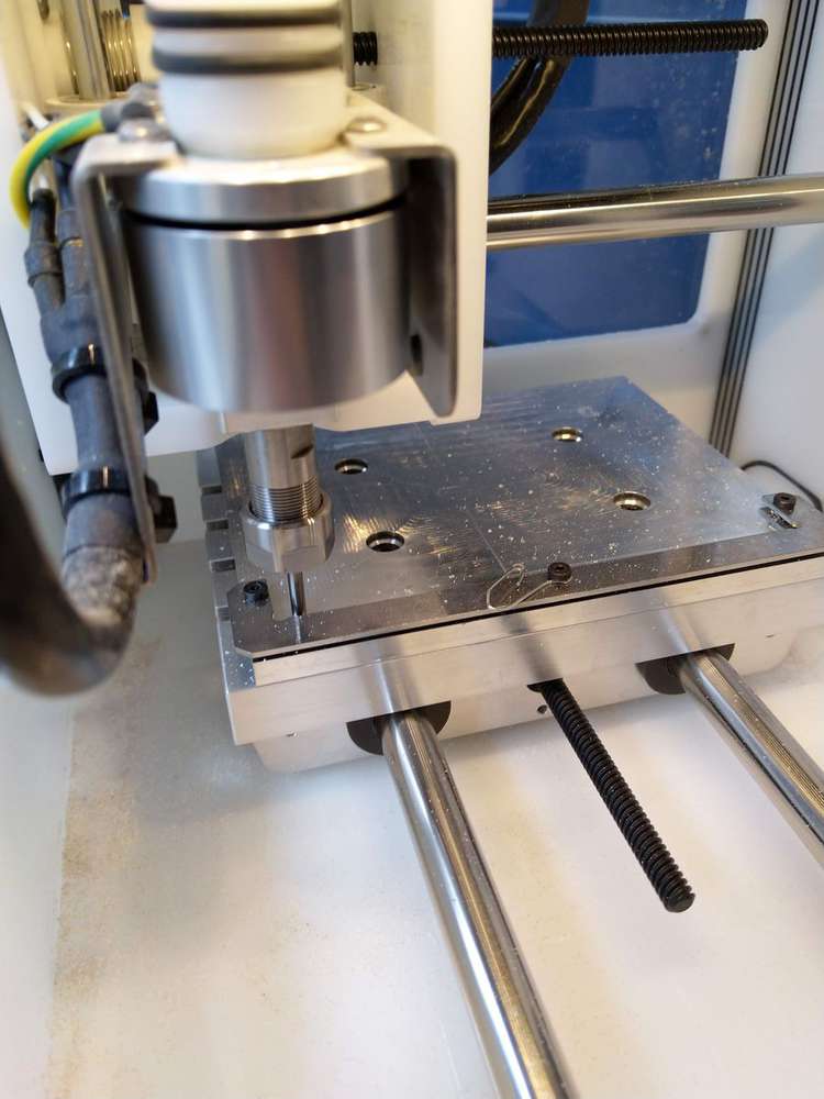
To mill the board, I’ve used the Othermill machine and 1/64 and 1/32 mill bit. I’ve got some issue with the two first try of double sided milling board. The two version were not aligned ( 2mm of error )
After checking a lot of things on the machine and the placement, I’ve find that the machine need to locate the fixturing by probing it. After doing this process, I’ve suceed in milling my board.
| Fail version | probing the fixturing |
|---|---|
 |
 |
| Top | Bottom |
|---|---|
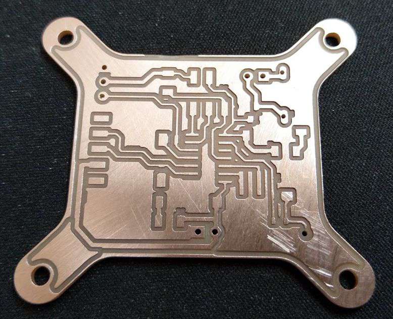 |
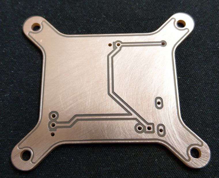 |
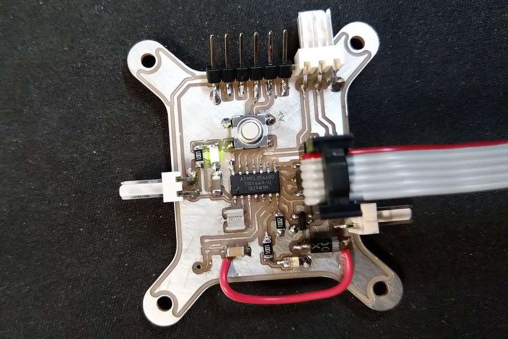
Soldering the board
Not a lot to say on this topic. I’ve soldered my board. You can see my previous assignment on the FabISP to see how I solder my PCB. It was exactly the same process here. I’ve just added a simple wire because one trace were damaged during the soldering process. I will need to make the less thinner for my next board.
| Top | Bottom |
|---|---|
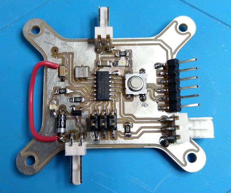 |
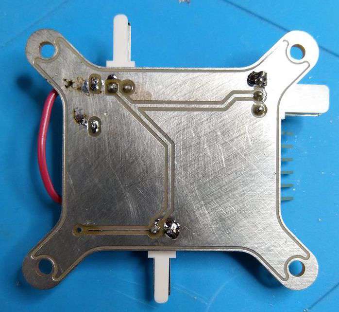 |
I also need to solder the hall sensor.
Testing and programming the board
First test, I’ve made a continuity test of the board, and it seems to be OK. So I supplied it, and the green LED turned ON so the board seems to be correctly supplied.
I’ve checked the voltage value on the board, and everything was okay, so I decided to test pushing some code in it.
To do that, I wanted to try the arduino IDE with my board ( before going into C language on Atom ). So I’ve tested some codes.
Blink LED
Status : Working 
const int LED = 6 ;

void setup()
{
  pinMode(LED, OUTPUT);
}

void loop()
{
  digitalWrite(LED, HIGH);
  delay(1000);
  digitalWrite(LED, LOW);
  delay(1000);
}
Push button
Status : Working
const int buttonPin = 2;
const int ledPin =  6;

int buttonState = 0;

void setup()
{
  pinMode(ledPin, OUTPUT);
  pinMode(buttonPin, INPUT_PULLUP);
}

void loop()
{
  buttonState = digitalRead(buttonPin);
  if (buttonState == HIGH)
  {
    digitalWrite(ledPin, LOW);
  }
  else
  {
    digitalWrite(ledPin, HIGH);
  }
}
Test sensor
Status : Working
Basically, it’s the same code than for the Push button as I used an TOR Optic sensor for my test, the OPB715Z. I’ve just change the value of the buttonPin variable like that
const int buttonPin = 3;
Test Motor
Status : Working
As the MOSFET is on the same pin than the LED, the code is the same than for the Blink LED test.
Hall sensor
Status : Not tested this week 
Before testing the hall sensor, I first need to solder it. So I’ve reserved this work for the week 11.
Results
I film myself doing the first test on my PCB. You will see the four tests I’ve made to check if the component and the board works well. And of cours, As for all my video, you can also enjoy the music “Canals” by Joakim Karud 