10 - Molding and casting
enough# 10. Molding and casting
This week, it’s molding an casting week. To do that, I will use as an example the molding of a wheel for my pedagogic robot Botly.
Assignments
- Explained how you designed your 3D mould and created your rough and finish toolpaths for machining
- Shown how you made your mould
- Shown how you cast the parts
- Described problems and how you fixed them
- Included your design files
- Included your ‘hero shot’ photos of the mould and the final object
- Reviewed the safety data sheets for each of your molding and casting materials, then made and compared test casts with each of them
The 3D design
The project
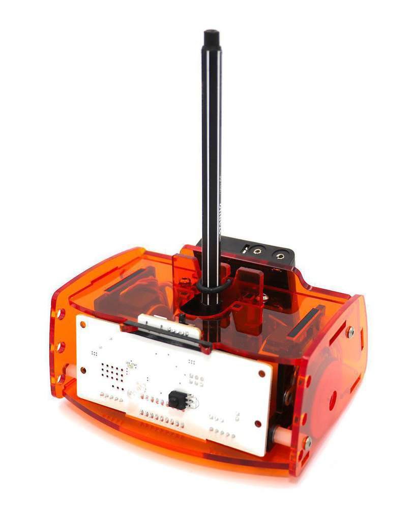
So for this week I would like to make a mold of the wheel of my pedagogic robot Botly. Botly is a robot that draw and can be programed by anyone using a dedicated interface based on Blokly framework from Google. With my team, we are working on this project since 2017 and all the robot is designed and produced by us :
- The frame are made by laser cutting 3mm PMMA
- The board is a dedicated one based on a Atmel 32u4 micro-controller
- The robot is driven by two stepper motors
- The pencil can go up and down using a servo motor
Actually, the wheel are 3D printed. But it’s not very efficient because the cylindricity is not optimal and the process is very time consuming. So, as a lot of people ask us for robot, I would like to test molding and casting the wheel to improve the quality of the part and the production time, because for the moment, it take 50 minutes to print just one wheel !
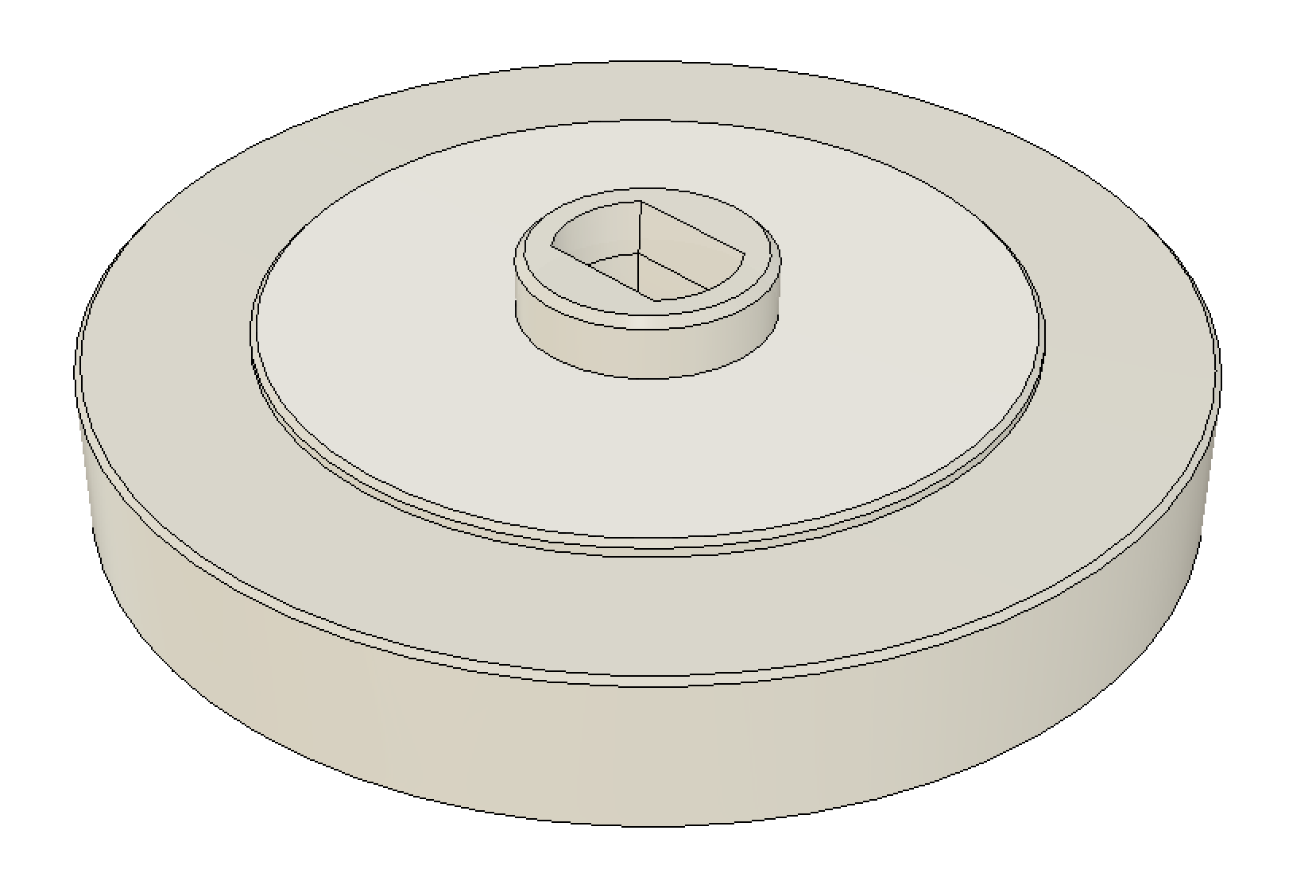
The actual wheel
The actual wheel look like this :
| Top view | Bottom View |
|---|---|
 |
 |
It’s clear that I will not be able to mold and caste the final part with just one process because I need more than 2,5 axes machine to mill the groove of the wheel. So, in my opinion, I would like to follow the following steps :
- Design a wheel without the groove
- Make a mold of this wheel into machinable wax
- Cast the wheel
- Make the groove of the wheel using a manual lathe
- Mold this new master piece
- Cast the final wheel
3D design
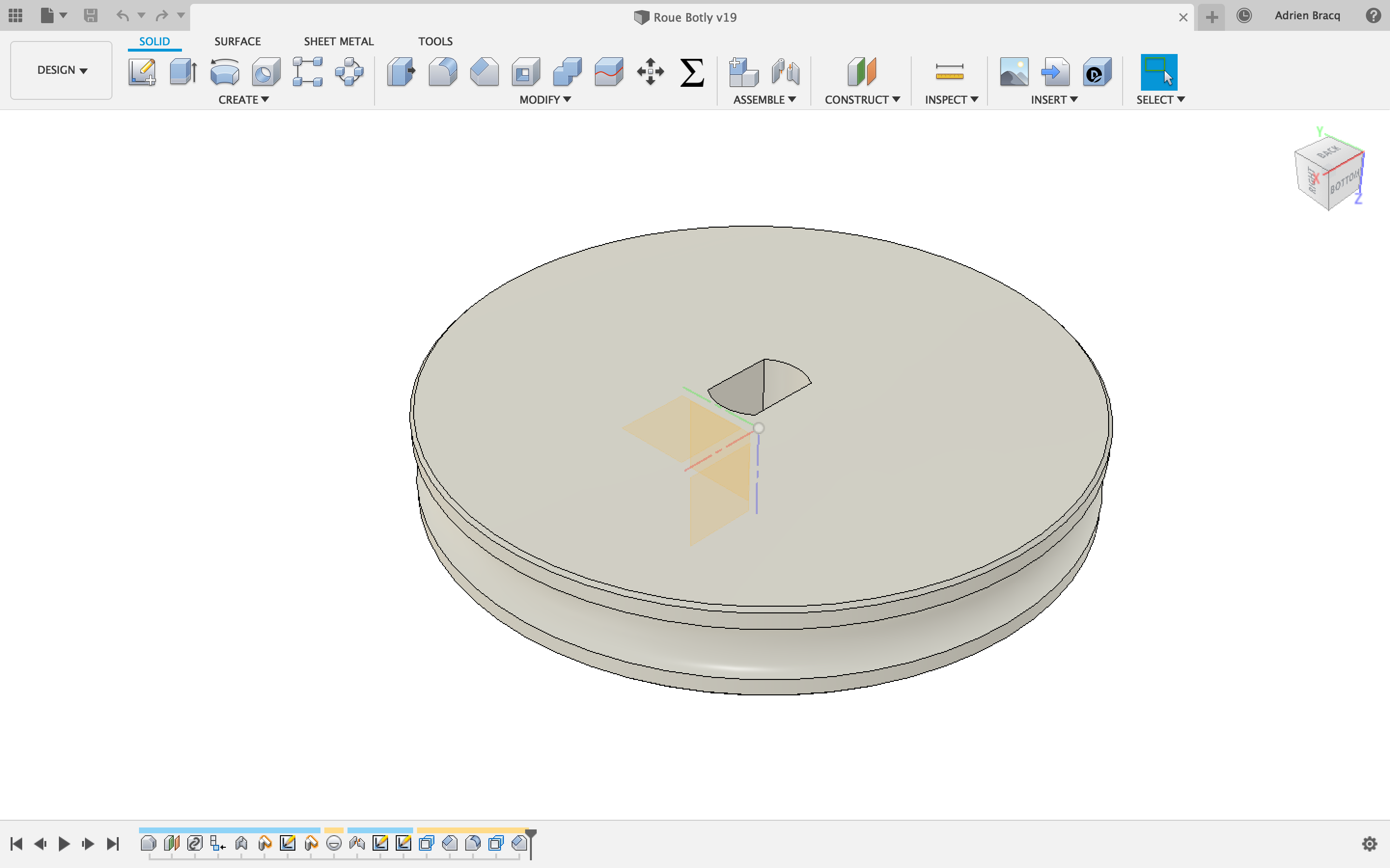
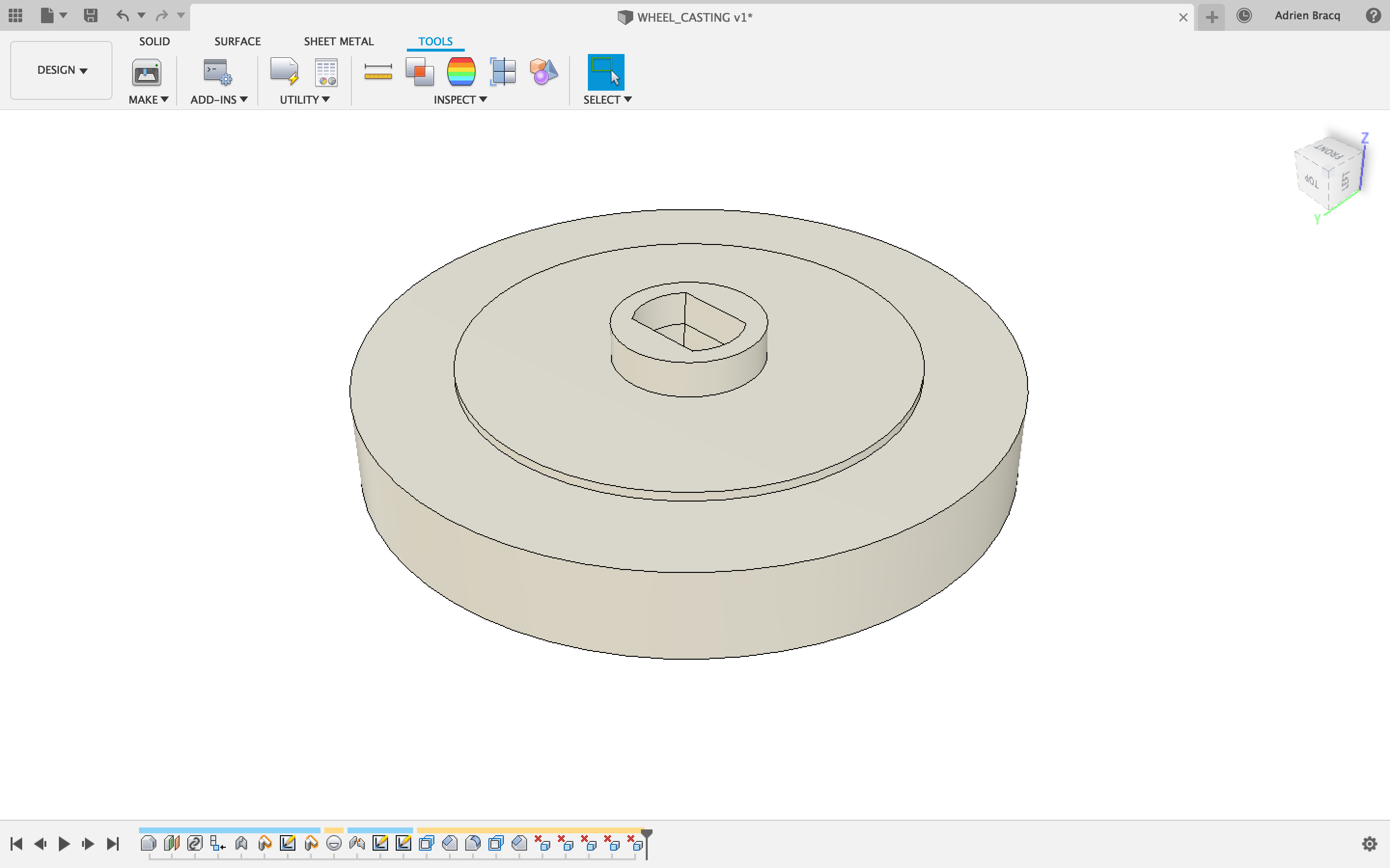
For this step, as my wheel is already designed into fusion, I will use this file and modify it to take off the groove.
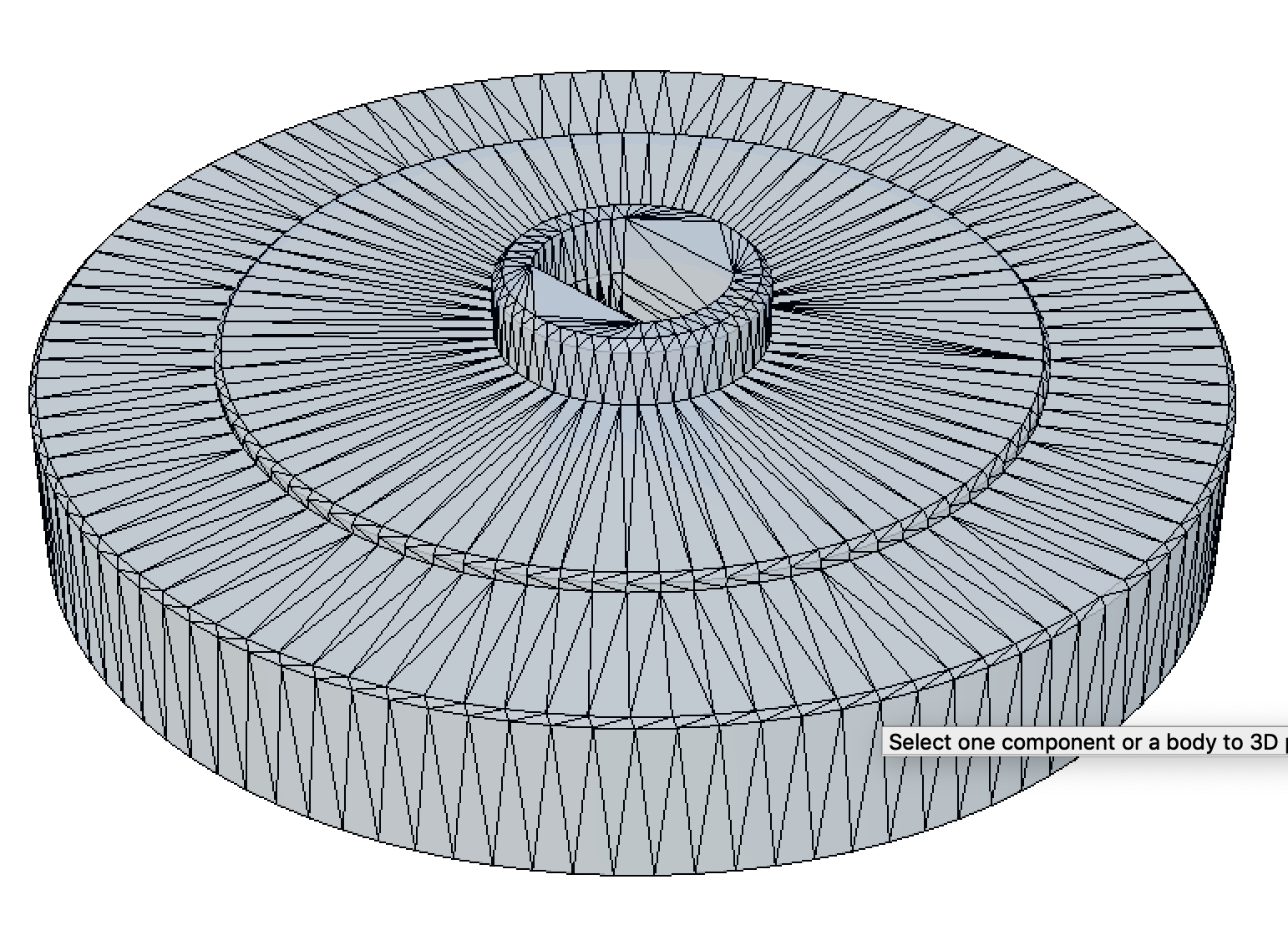
When the groove has been taking off, I have exported my file into an .stl and I am ready to importe it into my CAM software.
| Without the groove | Export the STL | STL view |
|---|---|---|
 |
 |
 |
Making the mold
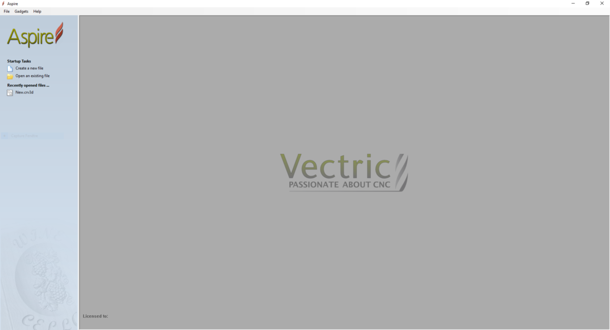
Aspire Vectric 4.0.1.5
To make the GCode for my CNC machine, I will use Aspire software from Vectric.
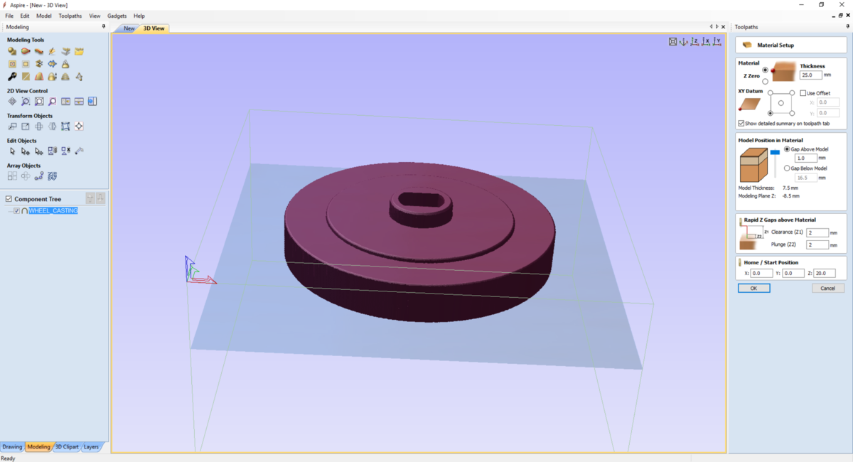
First, I will have to setup the job and material size and I will use machinable wax from inventables.
| Aspire Vectric | Setup the material |
|---|---|
 |
 |
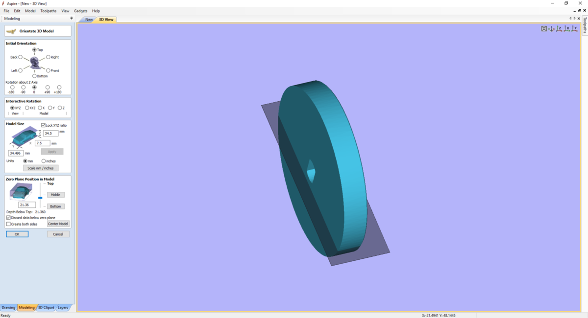
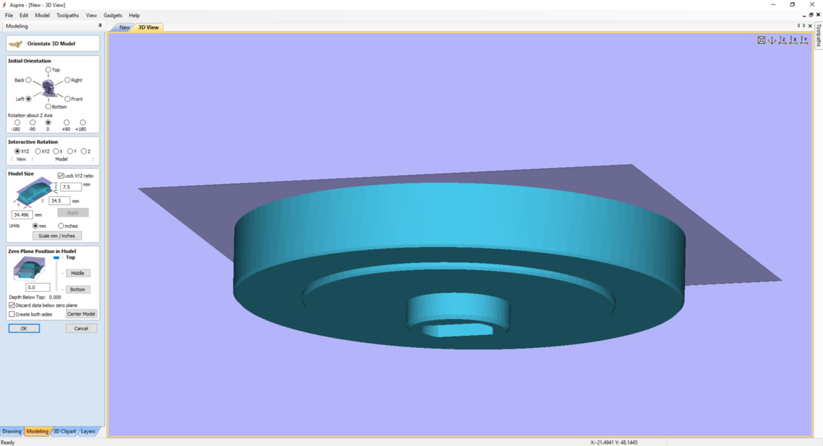
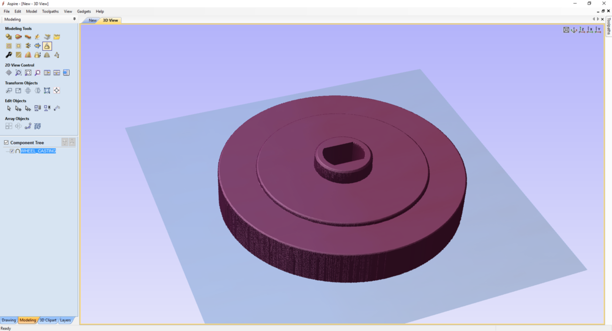
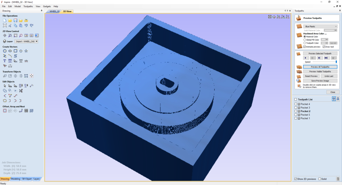
After that, I have imported my file into Aspire with the import function of the software. I will have to orientate the 3D model so it can be milled like a mold. I have also set my material to be sure that I let a gap of 3mm above the model so I have enough space to make my mold.
| Import the STL | Orientate the model | The model well oriented |
|---|---|---|
 |
 |
 |
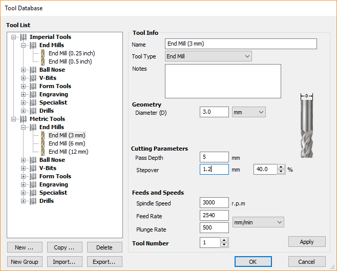
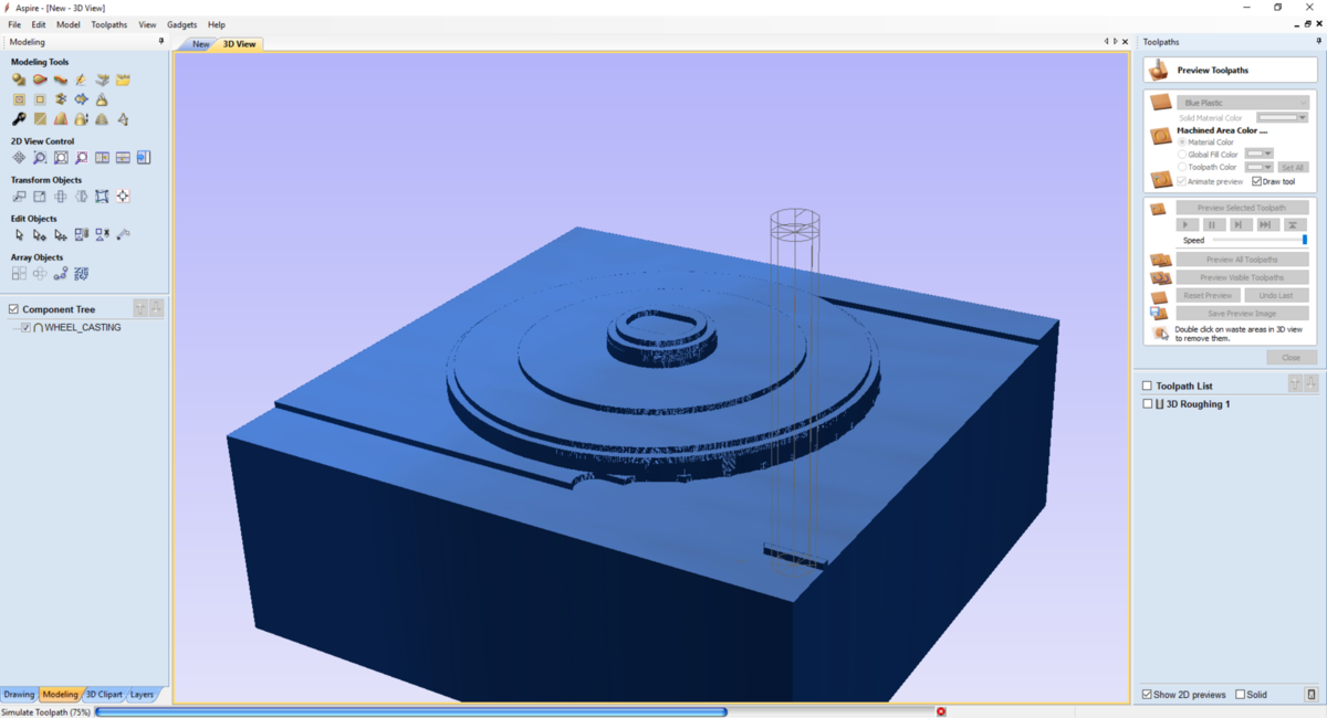
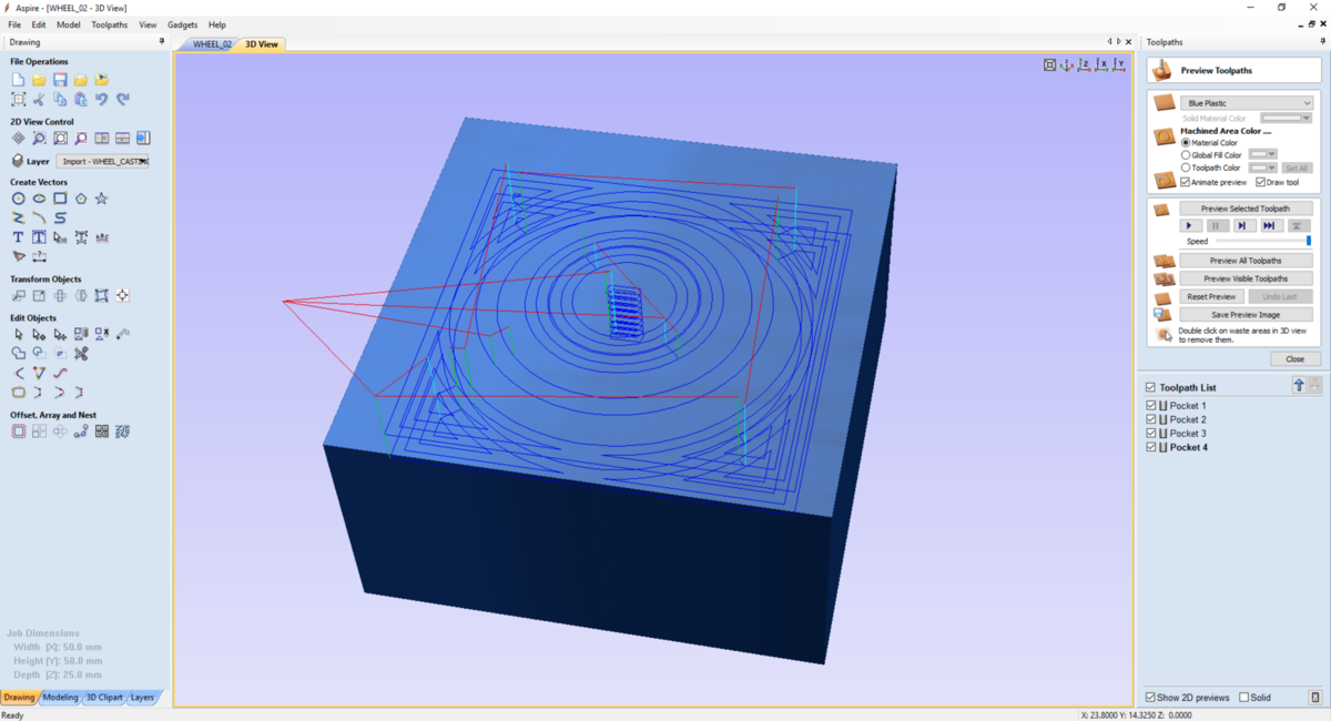
After, I made a first path of roughing with a straight end mill bit of 3mm. For the parameters, I use the one find into inventables documentation :
- Spindle Speed : 3000 RPM
- Feed Rate : 2540 mm/min
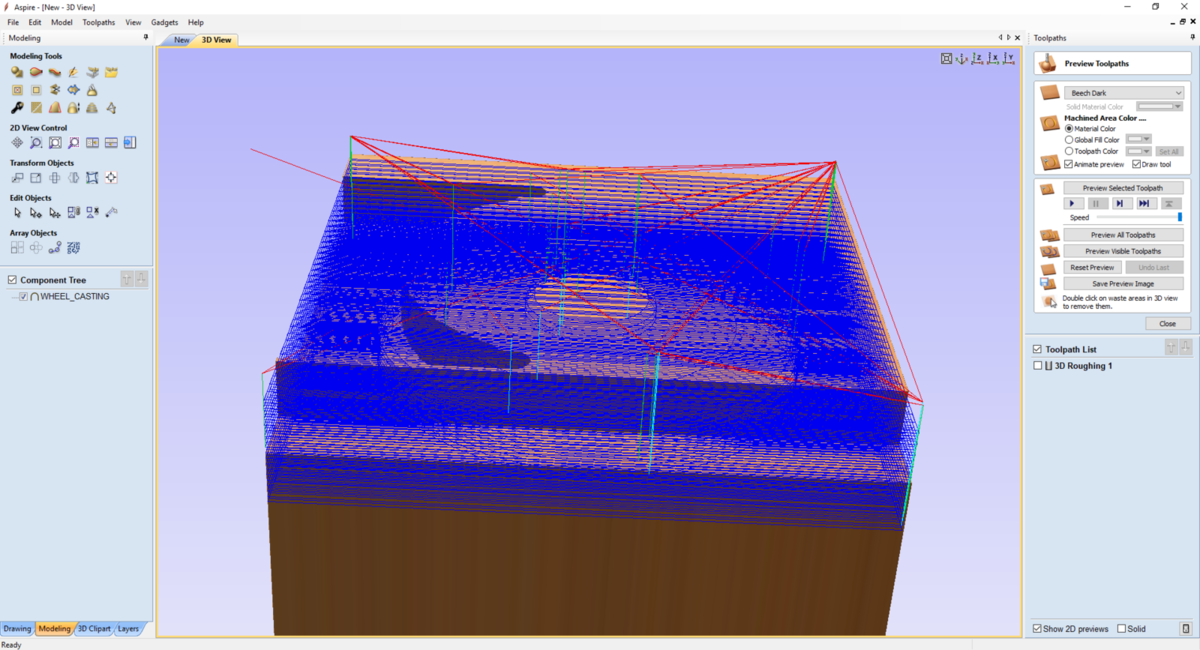
I have also let some machining allowance of about 0.5mm. I also change the path depth to have some details on the first roughing path. Pressing calculate and preview the path.
| 1 | 2 | 3 |
|---|---|---|
 |
 |
 |
| 1 | 2 |
|---|---|
 |
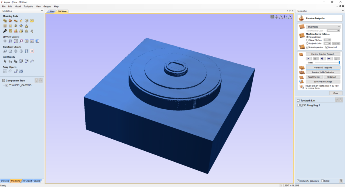 |
Next, I made the finish path with the following parameters :
- Spindle Speed : 8000 RPM
- Feed Rate : 1016 mm/min
But after previewing the result, I find that it will not be satisfying fo my use.
| 1 | 2 | 3 |
|---|---|---|
 |
 |
 |
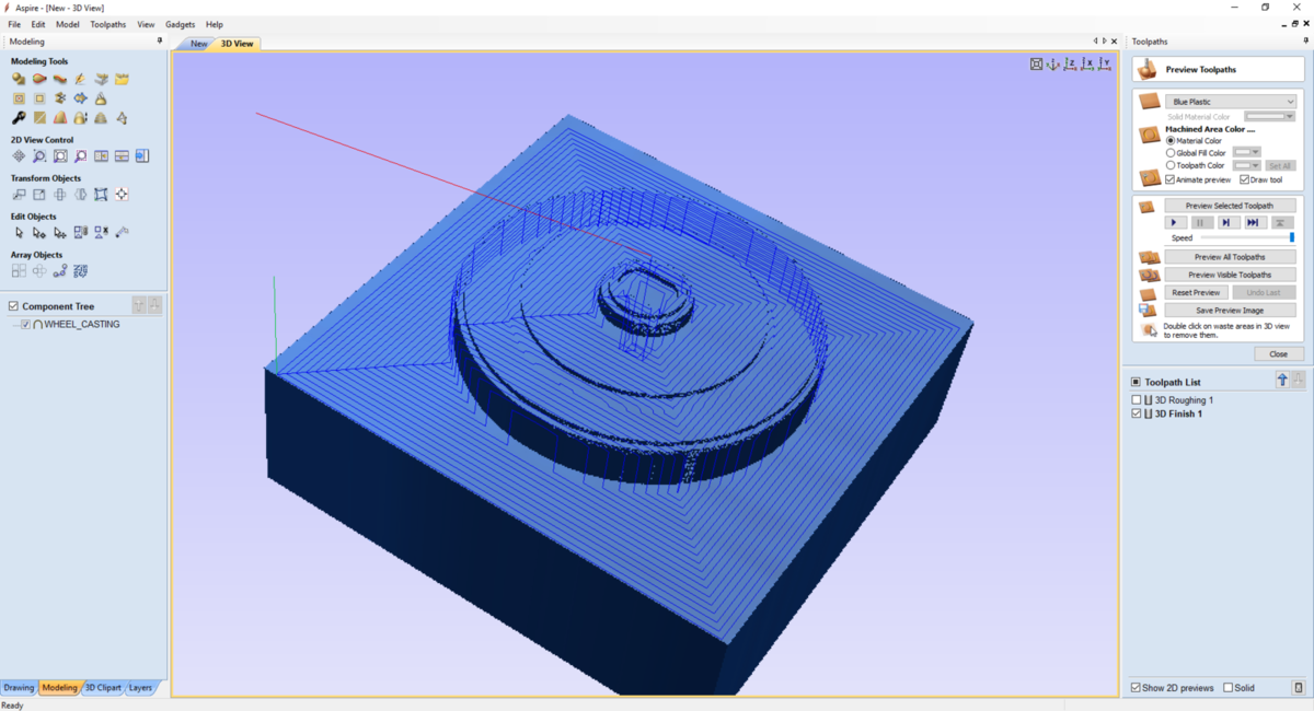
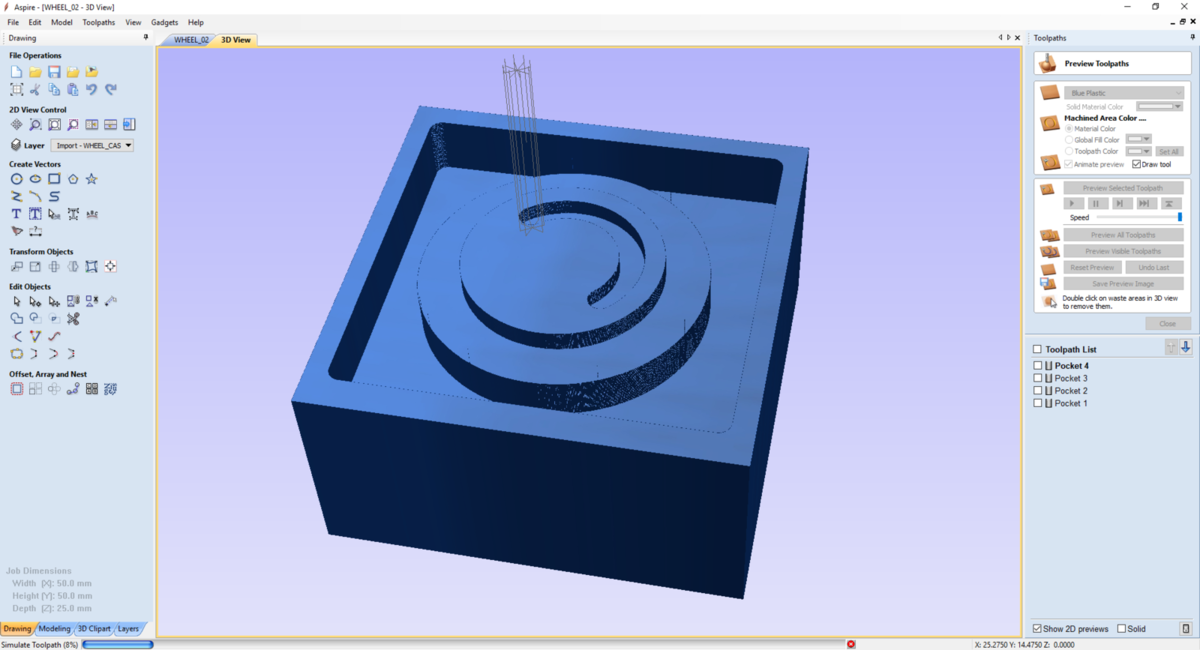
So I try to use the same tool and make an other roughing path but with an allowance of 0 mm and a path depth to 0,1mm and press test.
The results seems to be perfect, but the machining time will be verrrrrrrry long. So I decided to didn’t choose this solution and modify the way I generate my GCode.
My first error is to use an STL file as my part is mechanical part and not a modelled part.
Modify my design in fusion360
So, I will now try to make my Gcode from a dxf file so I can decided the best way to will it into Aspire. I will generate a pdf of the part with the drawing tool, and generate a DXf file into Inkscape.
First step, I cleaned my part and deleted the chamfer.
Second step, I generated the drawing from my part.
| Cleaning the part | Make a drawing | The drawing view |
|---|---|---|
 |
 |
 |
Warning
Be careful to the Scale of the part when you do that. the scale has to be set to 1:1.
After that, I generated a pdf file that I’ve imported into Inkscape to generate a DXF file. Now I can get back to Aspire
Aspire, the return …
In fact, after checking Aspire, it open also the PDF files. So the step to transform the PDF into DXF into Inkscape is optional.
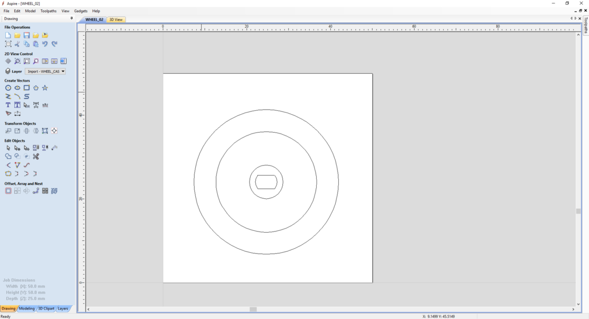
I’ve imported the pdf into Vectric and created a square around the model. So now I’ve access to all the vector so I can make all the path that I want to generate my file.
| 1 | 2 | 3 |
|---|---|---|
 |
 |
 |
Do do that, I’ve created a drawing of my part into fusion with dimension taken by the above of the part so I can have all the dimension of the deep of the path. I created 4 different toolpaths to mill my part, and the result is, as expected, more interesting for us, and I can modify easily if I want the deep of each path. For example, I will add 1 mm to the hole path to be sur that when I will do the casting, the silicone will flow inside.
| 1 | 2 | 3 |
|---|---|---|
 |
 |
 |
Generate the GCode
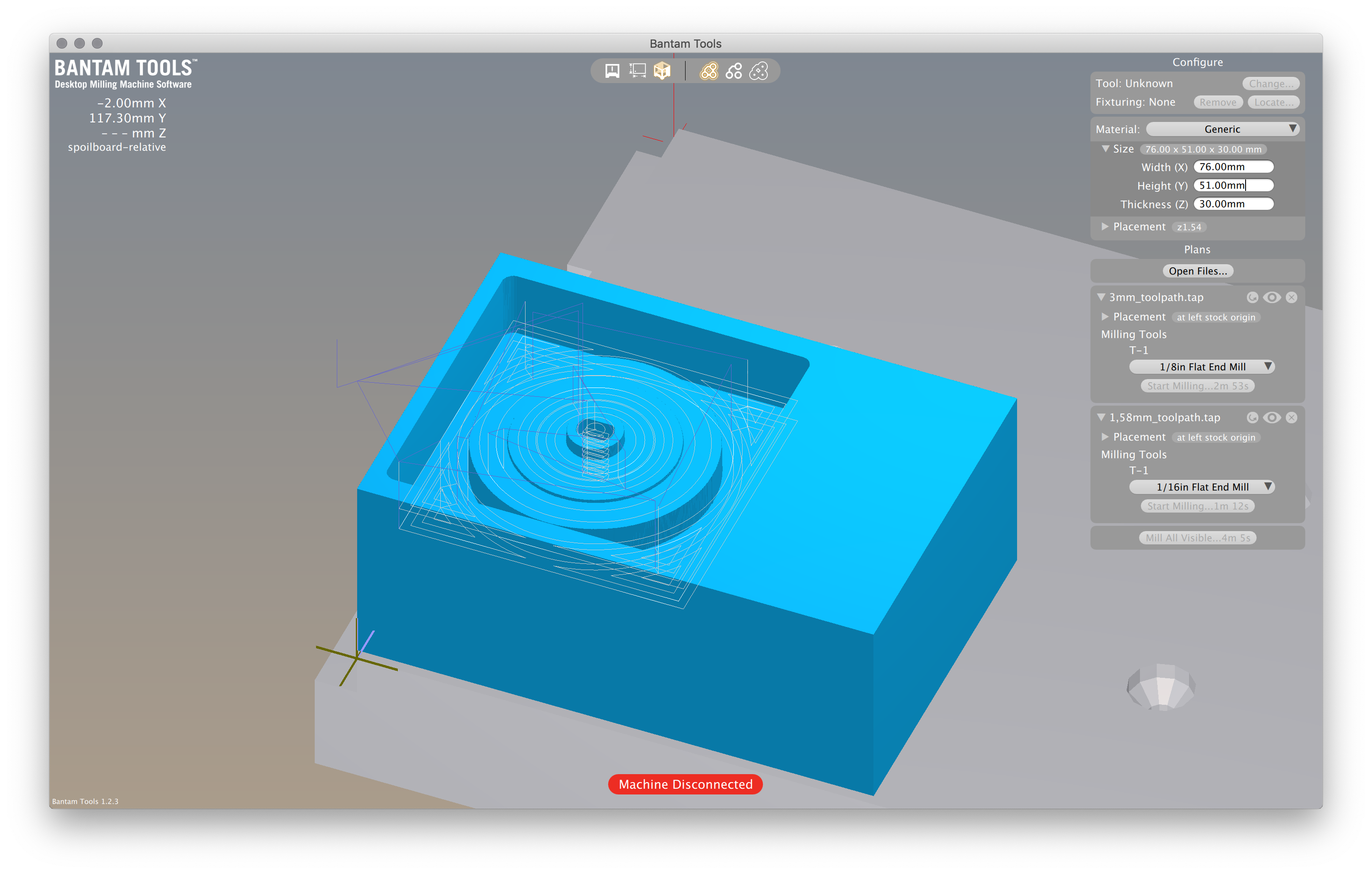
To generate the GCode, I will have to download the post-processor of my machine. As I will use the Othermill machine, I went to the vendor’s site and find the post-processor here.
The file has to be downloaded and put into the post-processors folder of VCarve. After that, I’ve generated two GCode because I’ve Two different tools.
Import the Gcode into bantamtools
After that, I imported the GCode into BanTamTools, and then just launch the process.
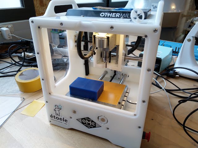
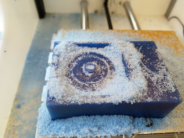
Milling
To mill my part, I will use the Othermill machine. The wax will be double tapped to the plate.
| Before milling | Milling … | Surprise ? |
|---|---|---|
 |
 |
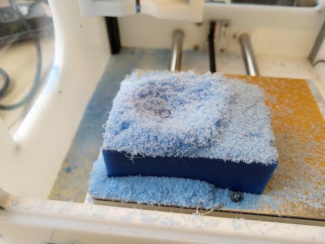 |
The result :
| Before cleaning | Result |
|---|---|
 |
 |
Making the Silicone mold
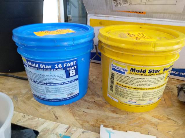
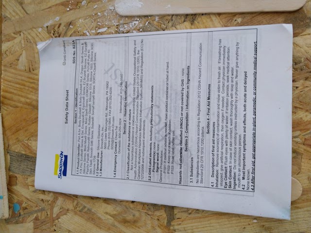
The product
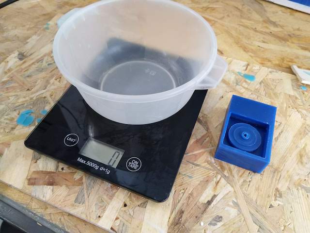
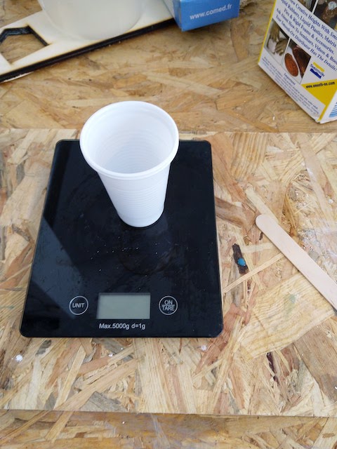
To make the silicone mold, I will use the silicon from Smooth-on. It’s the mold Star 16 FAST. I have also read the safety instruction that is always into the box of the product. I prepared my mixture into a plastic bowl, and use a balance to dose the product. It’s 1-1 product, so you have to put the same amount of A and B product. Very easy !
| The mold Star 16 FAST | The safety Datasheet | The tools |
|---|---|---|
 |
 |
 |
Making the mixture
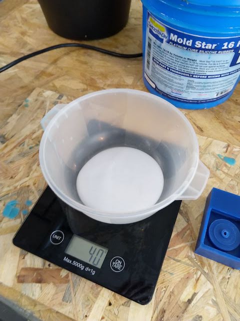
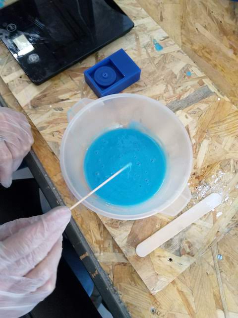
For my first attempt, I put 40gr of part A and 40gr of part B. I mixed them slowly to avoid bubbles and wait 3 minutes so the bubbles can be pulled up the mixture.
| Balance the mixture | Mixing |
|---|---|
 |
 |
Molding the part
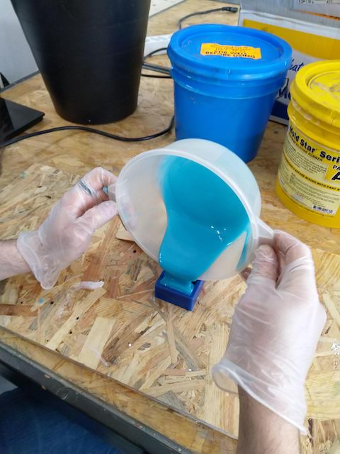
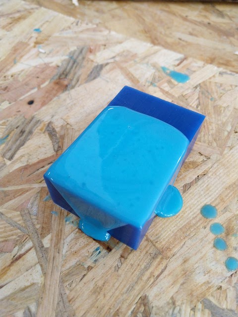
After preparing my mixture, I put it slowly into the milled part and wait till all the bubbles were pulled up.
| Put it into the milled part | waiting … |
|---|---|
 |
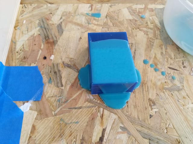 |
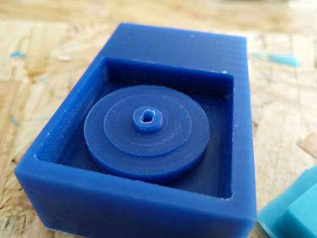
As I had some silicone in excess, I decided to make another mold of my 3D printed wheel.
| The wheel 3D printed | The quick mold I’ve made for it … |
|---|---|
 |
 |
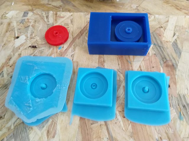
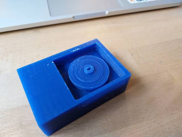
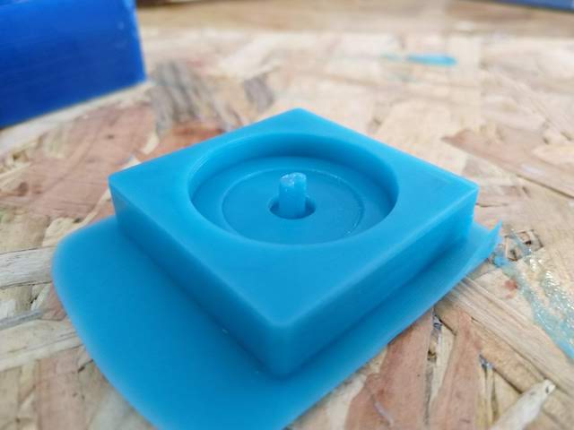
Unmolding the part
After 1 hour and a half, I decided to unmold the parts. The one with the 3d printed part worked very well as you can see :
| View 1 | View 2 | View 3 |
|---|---|---|
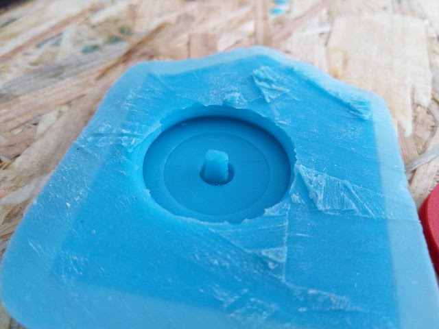 |
 |
 |
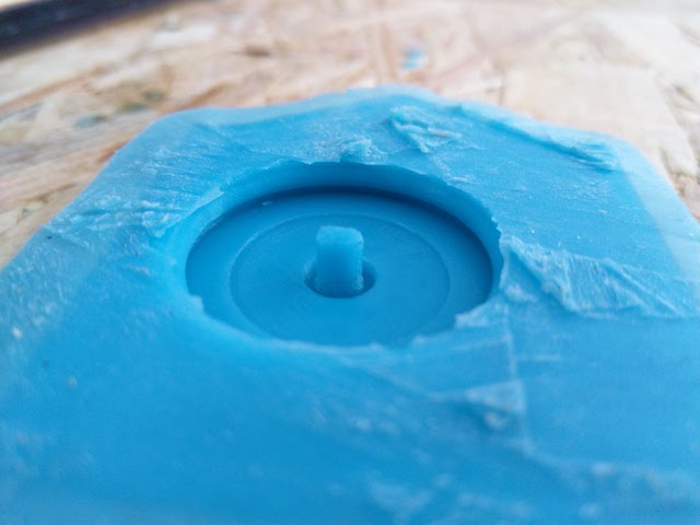
But when I unmold the one I milled, all the molding were perfect except the drilling … A bubble was trapped into the hole.
| View 1 | View 2 | View 3 |
|---|---|---|
 |
 |
 |
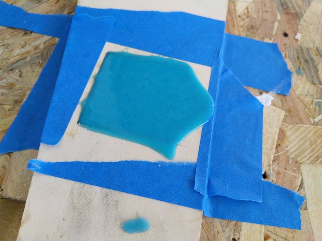
So I had to retry it and find a way to put the silicon into the hole, and avoiding bubble.
Molding the part, the return …
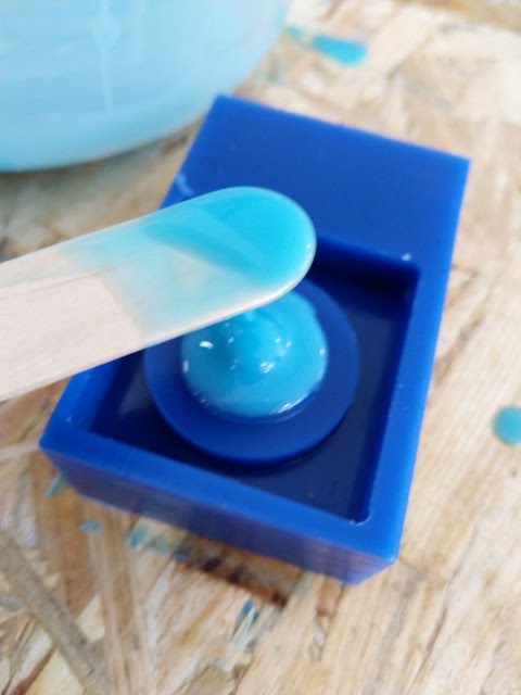
To avoid the bubble into the hole, I didn’t pour the mixture directly into the mold, but I use a tool to slightly put the silicone into the hole first.
| View 1 | View 2 | View 3 |
|---|---|---|
 |
 |
 |
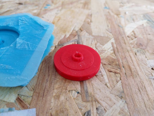
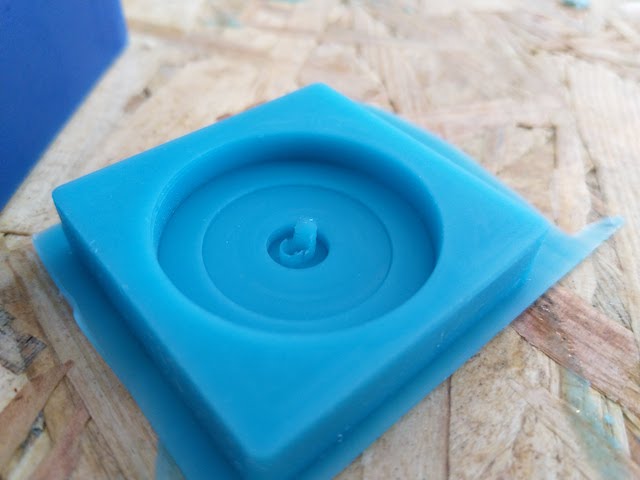
Unmolding the second try
And it’s a success !
So I can now go to the next step, Casting
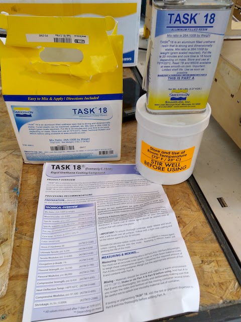
Casting
To cast the part, I used the TASK 18 from Smooth-on. It’s a relatively low viscosity aluminum filled urethane casting resin.
| The product and data-sheet | The ratio | The tools |
|---|---|---|
 |
 |
 |
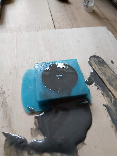
The mix Ratio is 26A:100B, so I have to use the balance to make my mixture. The process is the same than for the silicon.
I also use Ease release product from smooth on. This product will release polyurethane elastomers, epoxy resin, polyester resins, RTV silicones, rubber, and thermoplastic polymers. Effective on aluminum, chrome, RTV silicone, epoxy, rubber, and steel molds.
| The mixture | Ease Release 200 |
|---|---|
 |
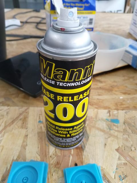 |
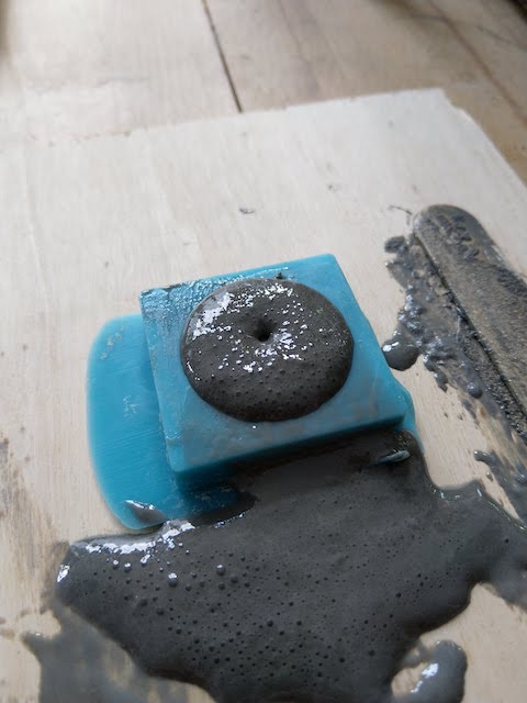
| Mold 1 | Mold 2 | Mold 3 |
|---|---|---|
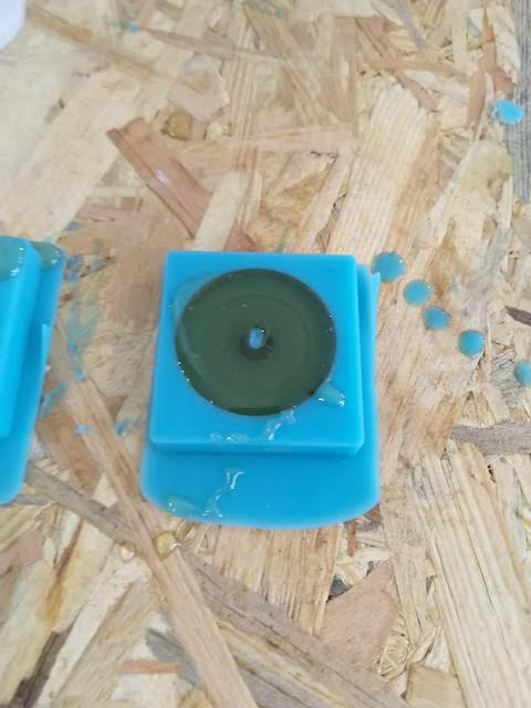 |
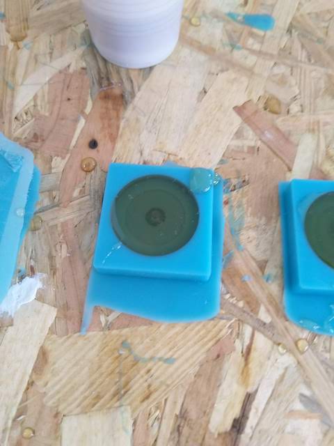 |
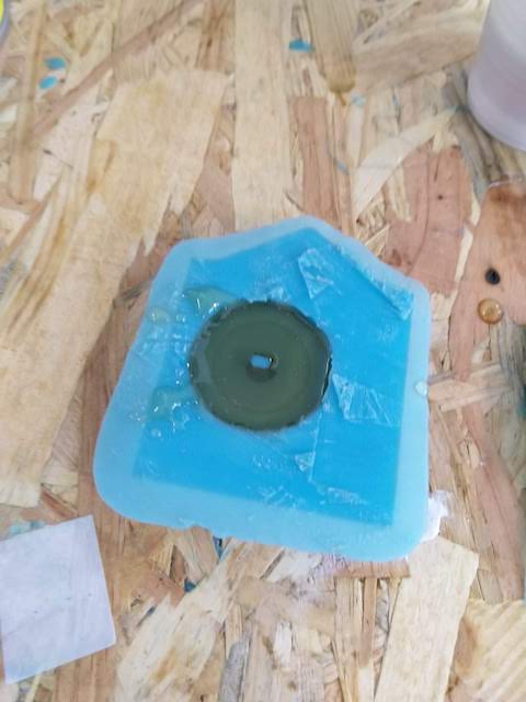 |
But my part didn’t dry because I didn’t mix the product enought and all the aluminum were still on the back of the pot. So I decide to clean the mold and try an other time with the same product.
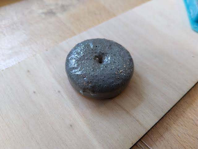
Results
| Before | After … |
|---|---|
 |
 |
After some drying time, the resin slowly started to gnawed, and the result were very bad. with the same resin, my friend Benjamin experienced the same problem with his mold for his final project. We don’t know if it’s a particularity of the resin or if the resin is not good at all.
| Recto | Back |
|---|---|
 |
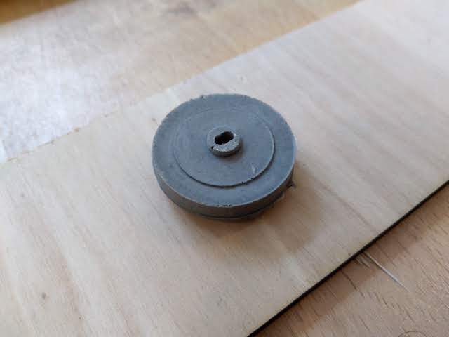 |
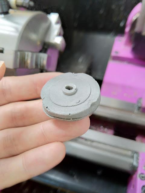
But, I decided to try to lath the part anymway…
Lathing the part
… and it didn’t work very well !  The piece was deformed at the first tightening in the jaw of the lathe.
Conclusion
As a conclusion, with any other type of resin, my mold could work. But for this assignment I would love to test the task18. And the result was for me a total disaster during the casting of the part. So, for the future, I will not use this kind of resin.