Laser Cutting
Assignments
This week We have to cut something with the laser and also design and cut a parametric press-fit kit. Our assignments were :
- Explained how you parametrically designed your files
- Shown how you made your press-fit kit
- Included your design files and photos of your finished project
The Press fit kit
- Explained how you drew your files
- Explained how you parametrically designed your files
- Shown how you made your press fit project
- Included your design files
- Included photos of your finished project
For my competition of robotic ( Makerfight and Eurobot ), we are making three different kind of robots. So I have decided to maker sticker of our logo on the Vinyl cutter.
To do that, I used two softwares :
- Fusion 360
- LaserCut
Design the files
I film myself doing the files. As for almost all my videos, the speed is x4, so you can, directly on youtube, increase the speed if you want, or slow down to the realtime speed ( x0.25 ). And of course, you can watch it at the normal speed and enjoy the music “Canals” by Joakim Karud 
You can find my files below :
Press fit kit :
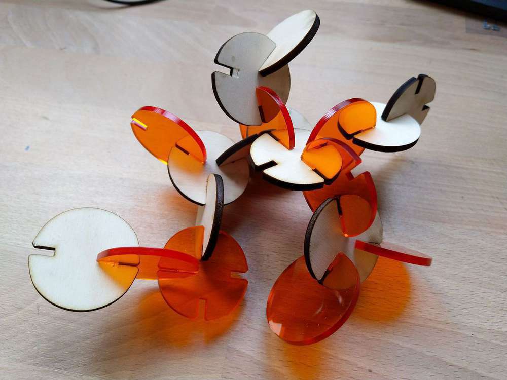
You can also visualize my project below :
The idea for this project is to always use a circle base form, and make modulation with the number of notches inside it.
Parameters
I have 4 main parameters in Fusion :
- Thickness : The thickness of the material
- Depth : The depth of the notch.
- LChamfer : The chamfer length
- LTotal : The total length of the part
LTotal is calculated with the other parameters :
Here you can see a pictures explaining how the parameters are working.

After that, I did a single version of my design so you can generate all the parts you want by added a parameter : The number of notches .
Concerning the skerf parameter, I will do this directly into the laser software which have a option for that.
Cut the file
Below you can see all the pictures I made during the cut of my project.


Result
Other projects
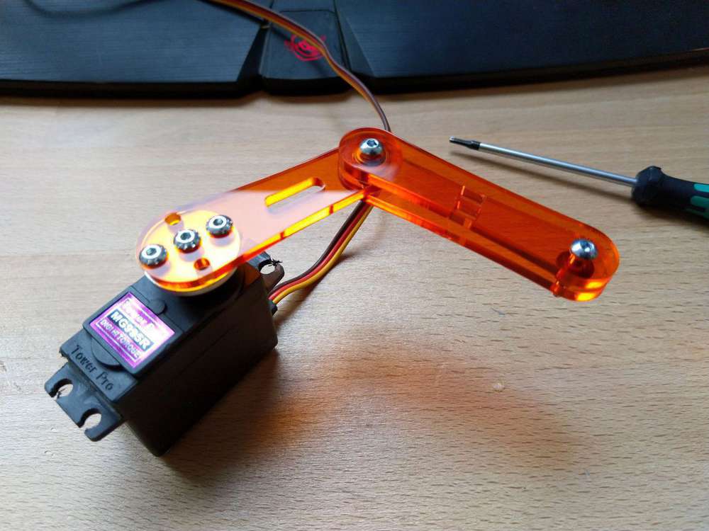
During this week I also made an other parametric design for my robot for the Eurobot cup. It’s a prototype of a rod-link to drive an arm up and down with a servomotor. You can find my design below.
I have 4 main parameters for this design :
- Thickness : The thickness of the material
- LArm : The arm length
- LRod : The rod length
- X/Y servo : Position of the servomotor that drive the rod
I adjusted the parameters so that the displacement of the platform is between 50 and 200 mm.
I cut it on plexiglass and assemble it to verify that all the parts fits well.


And here it’s the result assembled with the bearing and the servomotor :
You can find my files below :
Arm Rod :