Calibration - 3D printing
In fact, I have a 3D printer since 2013 ( an Ultimaker 1 ) so I print since this time and all the 3D printer of the lab are also ultimaker 1 printer. But since the last update of the firmware I’ve got some strange issue with the dimensions of my parts. So I decided to make a calibration file and try to solve this issue.
Machine presentation
The Ultimaker 1 is the first machine from ultimaker. It is a DIY machine you buy in kit and you have ta assemble yourself. It’s a very popular machine in the FabLab community and I have mine since 2013 …

Design a calibration part :
I designed my file with Fusion360 :

Here you can find the source file STL.
Fusion 360 have a great tool to export the .stl. You can choose the refinement of your model and directly send your file to your slicer.
| Basic tool | More options | Preview Mesh |
|---|---|---|
 |
 |
 |
Print the calibration file
Parameters for the print
To do my tests, I will use the parameters below into Cura 3.2.1. I used black PLA in 2,85mm.
| Menu | Parameters | Value |
|---|---|---|
| Quality | Layer height | 0.15 mm |
| Shell | Wall thickness | 0.8 mm |
| Top/Bottom thickness | 0.8 mm | |
| Infill | Infill density | 10% |
| Infill pattern | Grid | |
| Material | Temperature | 220°c |
| Diameter | 2.8 mm | |
| Flow | 110% | |
| Speed | Print speed | 50 mm/s |
| Infill speed | 30 mm/s | |
| Outer wall speed | 30 mm/s | |
| Inner wall speed | 40 mm/s | |
| Travel speed | 100 mm/s | |
| Build plate adhesion | Type | Brim |
| Brim width | 8 mm |
- Clic on the Prepare button.
- It took 2h of printing
- I put it on a SD card
Prepare the printer
First, you will have to set the temperature of your printer to the fuse temperature of your filament. For me, it’s 220 °C.
| Clean your plate | Open the extruder | Put the filament into the extruder |
|---|---|---|
 |
 |
 |
| Extrude “by hand” the filament | The fused filament should come from the noozle | Home your machine |
|---|---|---|
 |
 |
 |
Printing my file :
| Beginning of the brim | First layer | Second layer |
|---|---|---|
 |
 |
 |
Result :
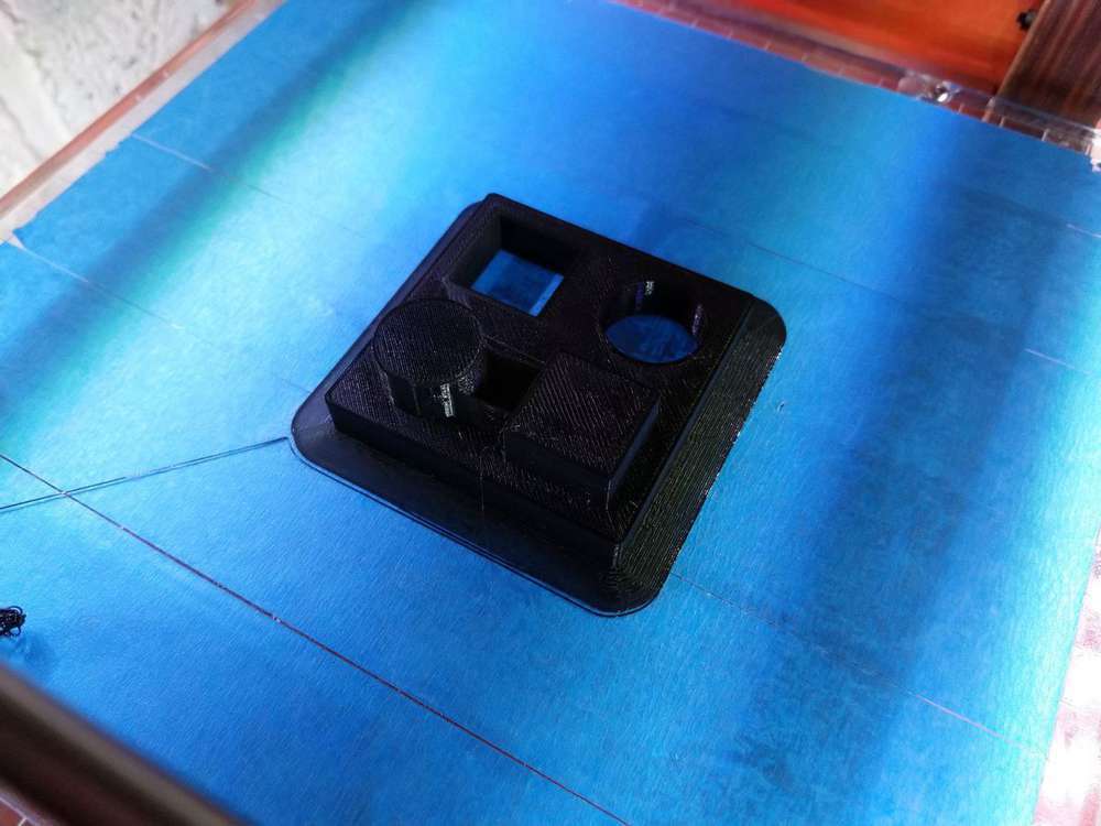
Measure and corrections
After the print, I took some dimensions as you can see below, an I compared them with those of my plan.
| Top view | Square outer dimensions | Outer dimensions |
|---|---|---|
 |
 |
 |
As you can see there are big offsets and I need to correct that. Below you can see a table with all the dimensions and the offsets :
| Info | Dimensions | Measures |
|---|---|---|
| Outer part | 60.0mm | 59.15 mm |
| Outer square | 20.0mm | 19.8 mm |
| Outer diameter | 20.0mm | 19.8 mm |
| Inner square | 20.0mm | 19.6 mm |
| Inner diameter | 20.0mm | 19.6 mm |
| Height Part | 10.0mm | 10.05 mm |
| Height Part | 20.0mm | 20.05 mm |
The offsets are very similar for the inner parts. The firmware of the Ultimaker 1 let you correct this offset by modifying directly into the menu the values steps/mm for each axis. The Z axis seems to be ok, but there is the same offset on the X and Y axis.
The value of X and Y are 078.74 steps/mm. So we will have to change it to correct it. I will use this fomula :
| Info | Dimensions | Measures | New Parameter |
|---|---|---|---|
| Outer part | 60.0mm | 59.15 mm | 79,87 steps/mm |
| Outer square | 20.0mm | 19.8 mm | 79,53 steps/mm |
| Outer diameter | 20.0mm | 19.8 mm | 79,53 steps/mm |
| Inner square | 20.0mm | 19.6 mm | 80,34 steps/mm |
| Inner diameter | 20.0mm | 19.6 mm | 80,34 steps/mm |
So I decided to test the parameter 79,87 steps/mm For a first try.
| The menu | Modification of the parameter |
|---|---|
 |
 |
Results
| First Layer ( seems to be better looking ) | Second layer | Measure OK |
|---|---|---|
 |
 |
 |
Conclusion
My Printer is now ready to print good parts. Let’s go to the 3D printing page for the following assignment.