Materials and Components
Here I put some informations about my choice on the electronical, electromechanical and mecanical components and materials that I will used into my project.
Summary of components and costs
| Components | Sources | Average prices |
|---|---|---|
| ATTiny44 | Multiple | ~ 1€ |
| Motor FF-030 | Multiple or recycle | 4€ ~ 6€ |
| Distance sensor OPB720B-12Z | Mouser, Digikey, Radiospare | 12€ |
| Hall sensor A 1324LLHLT | Mouser, Digikey, Radiospare | 2€ |
| Other electronical component for the PCB | Mouser, Digikey, Radiospare | 4€ |
| Silicium Mirror | Ebay | 10€ |
ATtiny 44
Specifications :
To make my beacon working, I will need to have a micro-controller to
- Control and regulate the speed of the motor using a hall sensor
- Read the distance sensor
- Calculate the distance between our robot and the opponent
- Calculate the angle of the position of the opponent robot
- Send the opponent position to another device
As the PCB need to be put into a very low spaces ( PCB of less than 10 cm diameter ), and as the beacon as to be low price, I choose to use a very simple but sufficient microcontroller, the ATTiny 44.
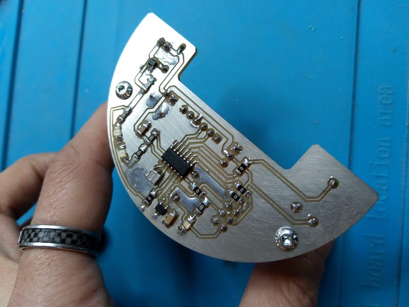
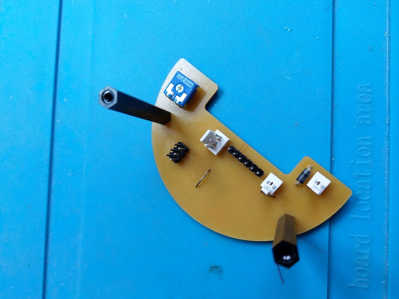
The board I build for my final project is documented into the assignments pages of week14.
Please see the related pages fo more informations.
| Top side | bottom side |
|---|---|
 |
 |
Motor
Specifications :
For the motorization of the beacon, I don’t need a very powerful motor but it has to be cheap and very small. Concerning the technology, I could use three kind of motors that I identified, and I try to find the advantages and disadvantages for my project :
| Motor type | Advantages | Disadvantages | Price comparison |
|---|---|---|---|
| Brushed DC | easy to find or recycle, very low price, easy to control, lot of size and choice | need speed reduction, low torque |  |
| Brushless | high torque, | need speed reduction, need specific driver, current consumption, too big | |
| Stepper | easy to find or recycle, lot of size and choice, angular position | current consumption, low speed | |
So, regarding this tab, I choose to work with a DC brushed motor. To find my motor, I’ve first list all the criteria it need to be fulfilled for my project, that is :
- Very low price (few €/$ or free if find into some recycle machines or toys)
- Small form factor (between 10 and 25 mm)
- Could be drive in 5V
- Low current consumption (under 500mA)
Choice :
A very popular motor (or type of motor) is the Mabuchi FF-030 which is a standard DC brushed motor use in a lot of different kind of applications. So you can by it for a very few dollars or just recycle it because you can find it in a lot of toys and the same form factor is used for vibration motor.

So it’s a vey good candidate for my project. And for information, the term “030” stand for the kind of mecanical dimensions of the motor. So, you can also find a lot of other type of motors, and not only Mabuchi’s one, from different brand that are compatible with this one.
The one I choose to use is a solarbotics motor that I had in the FabLab. The characteristics are the following :
| Characteristics | Value (at 4,7V) |
|---|---|
| Speed | 7400rpm |
| Current consumption | 150mA |
| Torque | 4 gm*cm |
| Stall torque | 17 gm*cm |

3D CAO :
To make my project, I’ll need to have the 3D CAO file of the motor. I used Fusion 360 and the above drawing of the motor to make it. See below :
Distance sensor
Specifications :
For the beacon, I need to find a efficient sensor but with the same problematic than the motor. It has to be :
- Very low price
- Small form factor (between 10 and 25 mm)
- Could be drive in 5V
- Low current consumption
- Reflective use
- If Laser, it has to be class 1M for security purpose
Choice
To detect only the opponent robot, I decided to use the reflective principle. The opponent will have a reflective passive beacon with a constant size and diameter. So I need to find a sensor that work in a reflective mode and fulfilled the rules of the french cup of robotics concerning the laser class( <class 2M for lasers).
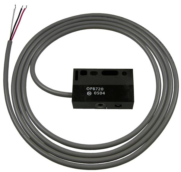
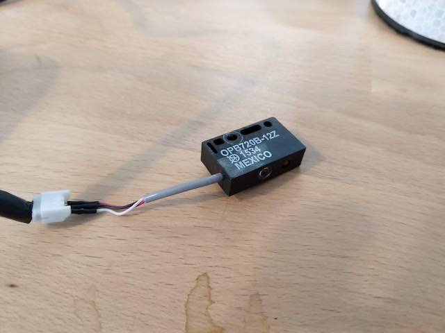
I found a perfect one from Optek. It’s a sensor from the OPB720 series. As we can see into the datasheet :
The OPB720A and OPB720B Series reflective switches detects objects as far away as 12” (305 mm) using standard 90% reflective material, and can detect objects as small as 0.08” (2 mm). The OPB720 series consist of three standard reflective switching distances -06Z for typically 6” (152 mm), -12Z for typically 12” (305 mm) and -30VZ for typically 30” (762 mm). The power supply voltage range of the OPB720A series is 10 to 30 volts while the power supply voltage range for the OPB720B is 4 to 7 volts.

The OPA720A and OPB720B sensors are NOT affected by ambient light in most conditions. Ambient light conditions are compensated by using a synchronous driver detection scheme.
So, for my use concerning the supply voltage range of our project, I will use the OPB720B version in 5V.
Also, regarding the range informations into the datasheet, the 12Z version is very interesting because it’s an infrared version of the sensor with a maximum detection of 0.04” to 12” (1.0 mm to 305 mm) 39” (991 mm) lead length with 28 AWG wire, using white 90% reflective paper.
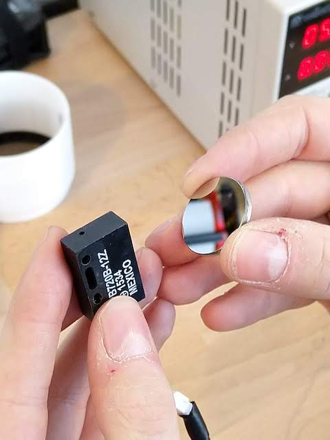
So, my choice will be to use the OPB720B-12Z version.
Concerning the output, this sensor has a logical output that switches from a high level with reflective target to a low level with no reflective target. With the addition of hysteresis, the OPB720 series minimizes output switching oscillations. So, it’s perfect for my use because I don’t need any analog input and I can use directly the internal pullup of the ATtiny to read the sensor.
3D CAO :
I used the drawing inside the datasheet to make the 3D model of the sensor into fusion 360 :
Hall sensor
To control the speed of the rotating part of the beacon, I will used a hall sensor directly soldered on the PCB, and magnets will be put on the rotating part so I can detect the speed and control it.
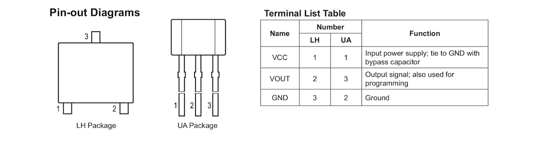
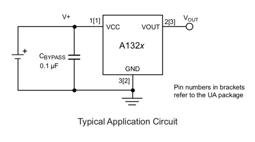
To do that, I’ve choose the hall sensor A 1324LLHLT. It’s a low noise linear hall sensor with an analog output.
All my work and presentation of the sensor has been done during week 11. So you can see it on this page.
| Pin-Out Diagrams | The typical application circuit |
|---|---|
 |
 |
Silicium mirror
Search :
As I don’t want to rotate the sensor because of the cables, I need to have something to reflect the signal of the sensor. The issue is that if I use a classic mirror, the sensor detect the mirror instead of detecting the reflection of the object into the mirror. But I knew that it was possible to do it because I already saw this kind of technic into similar conception.
Searching about that, I remembered that inside Laser cutter there are some special kind of mirror that can reflect laser. So, I tried my sensor into the mirror of the laser cutter of the FabLab, and it seems to work.
Tests :
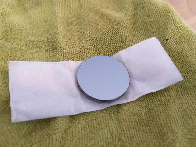
To verify this correctly, I ordered a silicium mirror for CO2 laser, and made some test with my sensor.
| The sensor | The mirror | I put a pullup on the output of the sensor | 5V supply |
|---|---|---|---|
 |
 |
 |
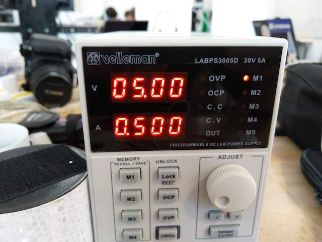 |
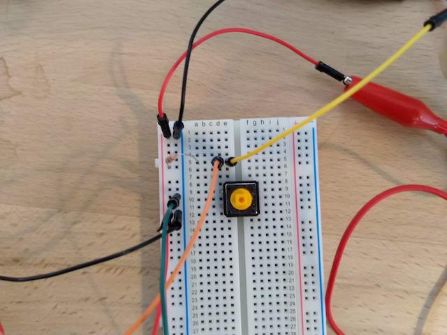
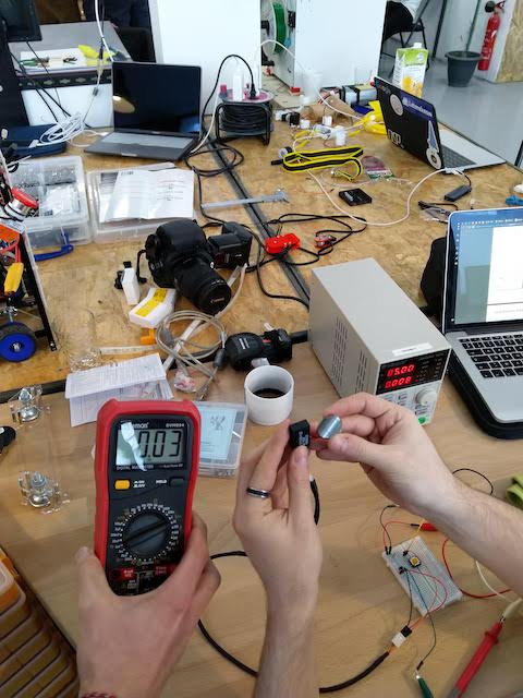
The idea is to quickly test the sensor with the mirror. So I manually took the mirror in one hand and in the other hand the sensor. Normally, when nothing is detected, I’ve to measure 0V. And when I put a reflective surface near the mirror, the sensor should detect it and the voltage should be near 5V.
The experimental protocol  |
With nothing | with a reflective surface (the passive beacon) |
|---|---|---|
 |
 |
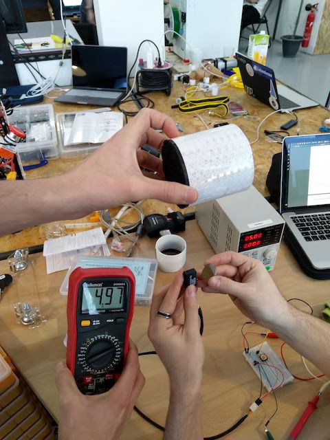 |
And it worked very well !
So now, I’ve a solution to detect my passive beacon that will be put on the opponent beacon mast, and I need to make my mirror turning so I can detect in 360° the position of the opponent.