Mill, solder and test the FabISP board
Assignments
Now that we have the correct workflow to mill PCB, We will use the machine to mill the FabISP board and we will then solder it and test it.
- Described the process of :
- milling
- testing
- soldering
- de-bugging
- programming
- Find the correct workflows
- Explain your choices
Milling
So first of all, we have to mill our PCB. We will use the parameters found during the characterization process to do that.
I choose to mill the FabTinyISP because there are less components and the shape of the board is more complex and I want to experiment withe complex of board because for my final project I will probably need to will board with complex shapes.
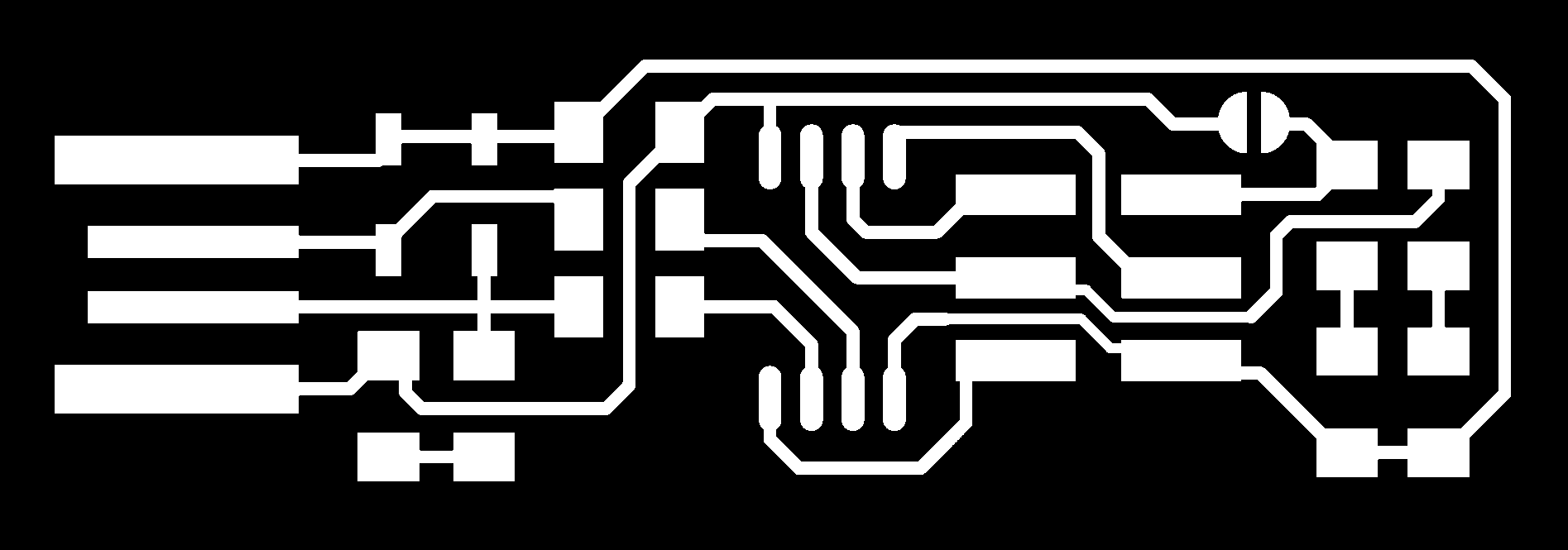
So first of all, I’ve downloaded the two .png file on this page:
Concerning the workflow I have :
- Vectorized the .png using Inkscape
- Imported the .svg file into BanTamTools
- Used the parameters found here
- Putted the copper board FR1 into the machine
- Automatically probed the thickness of the board
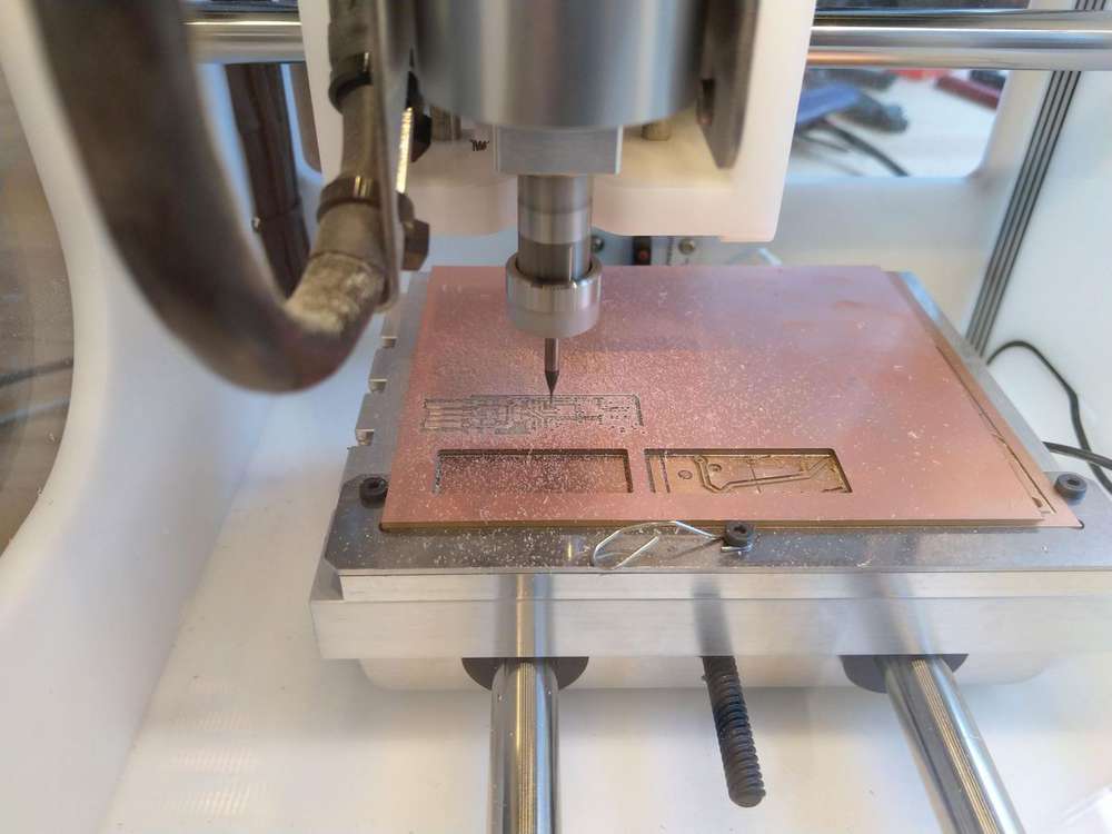
- Launched the milling process
| The BanTamTools soft during milling | Milling of the board | End of the process |
|---|---|---|
 |
 |
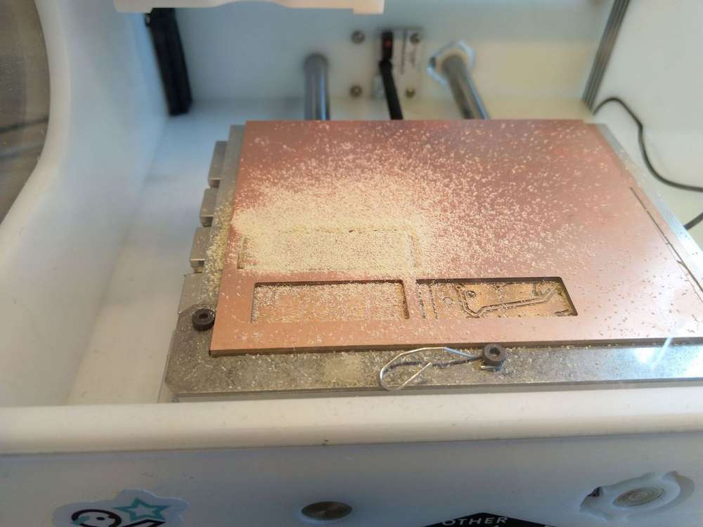 |
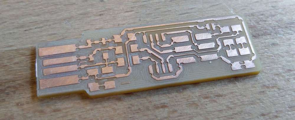
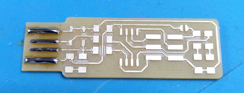
But, the result was not a great as expected … I got some strange hole on the traces and on some pads. After cheacking the parameters and the tool, I find that the 1/64 tool was not correctly put on the machine. So I decided to retry the milling and double check the tool before milling.

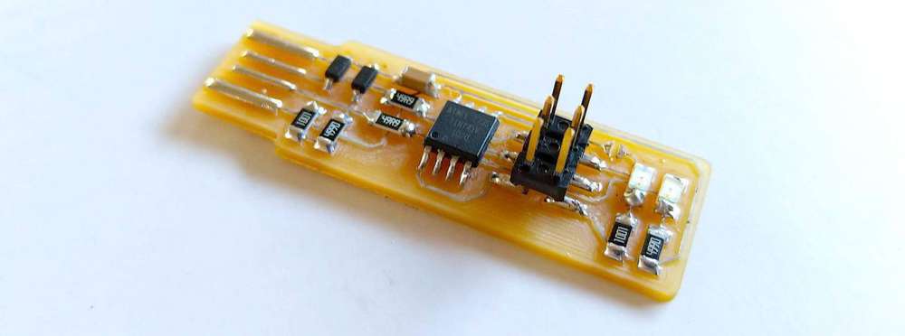
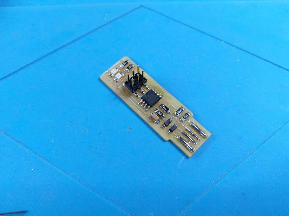
The results was great this time so I decided to keep this board and solder it.
Tinning
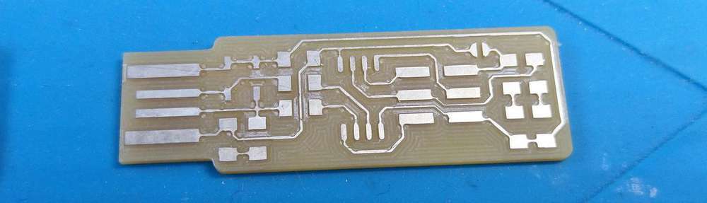
Before soldering the board, I decided to cold tin the board so it will help me to solder it correctly. To do that I used a special product that will tin the copper board.
Warning
Be careful during the process. The board don’t have to be plunged into the product more than 1 minute. Otherwise, the copper layer can be weakened.
After tinning process :
Soldering
Tools
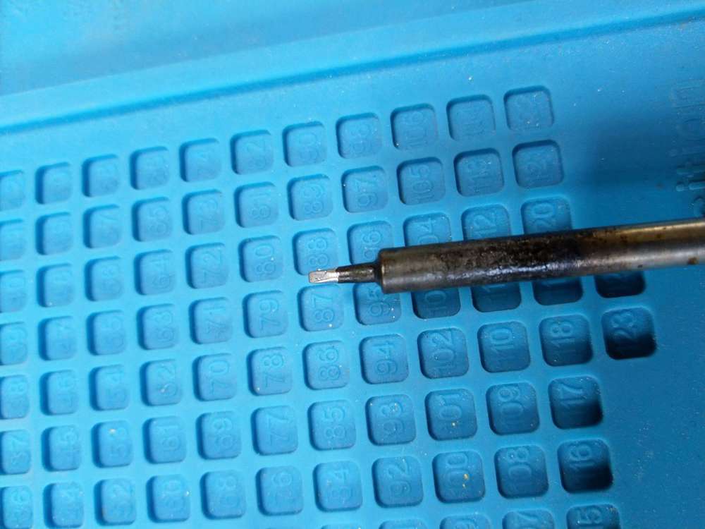
Is used two different iron tip to solder my board and I have the chance to have two iron in the same time so I didn’t has to change the tip all the time.
| Large tip | Thin tip |
|---|---|
 |
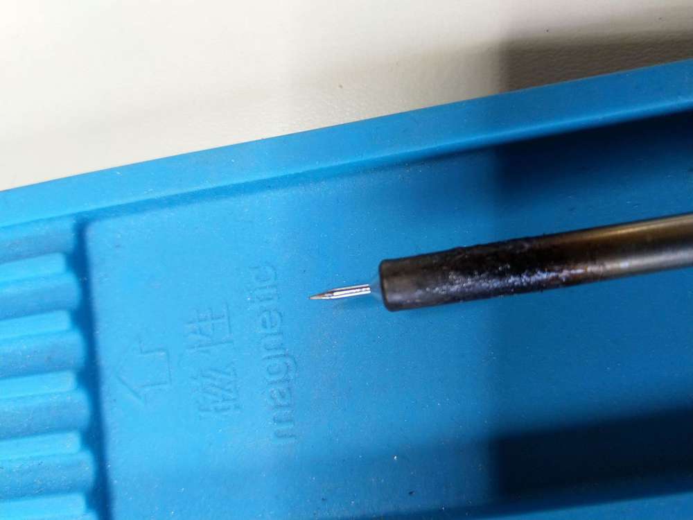 |
I used the large tip to make some roughing jobs like put a lot of tin onto the USB pad, and the thin tip for precision jobs.
I also used some welding flux to help during the soldering process and some tweezers to manipulate the components.
Process of soldering SMD components
For every components I followed nearly the same process :
- Put some welding flux where I will work
- Put some tin onto just one pad where the component will be solder
- Take the component with the tweezers and put in place
- Solder the pin of the component where I previously put some tin
- When the component is correctly in place solder the others pins of the component
- Inspect the solders and correct it by removing or adding tin
Solder the pad of the USB
I’ve just put a lot of tin on the pads with the large tip.
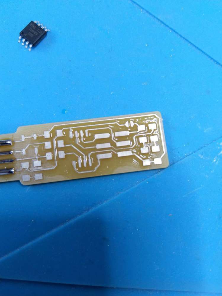
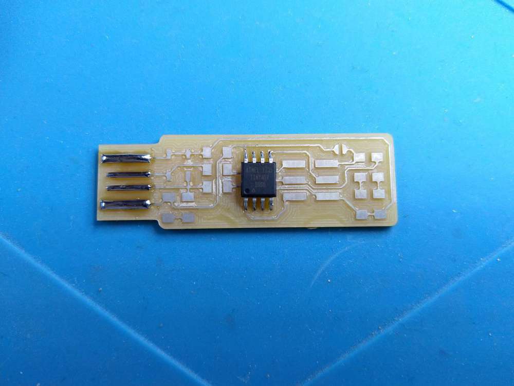
Solder the ATtiny45
To solder this kind of components, I followed this process
- Put some welding flux on all the pads of the component
- Put some tin onto just one pad where the component will be solder
- It will be an external pin of the component
- You don’t need to put a lot of tin
- Take the component with the tweezers and put in place
- Solder the pin of the component where you previously put some tin
- When the component is correctly in place, solder the exact opposite pin
- Solder all the other pins
- Inspect the solders and correct it by removing or adding tin
| Put some welding flux | Solder one pin | Solder the opposite pin | Solder all the other pins |
|---|---|---|---|
 |
 |
 |
 |
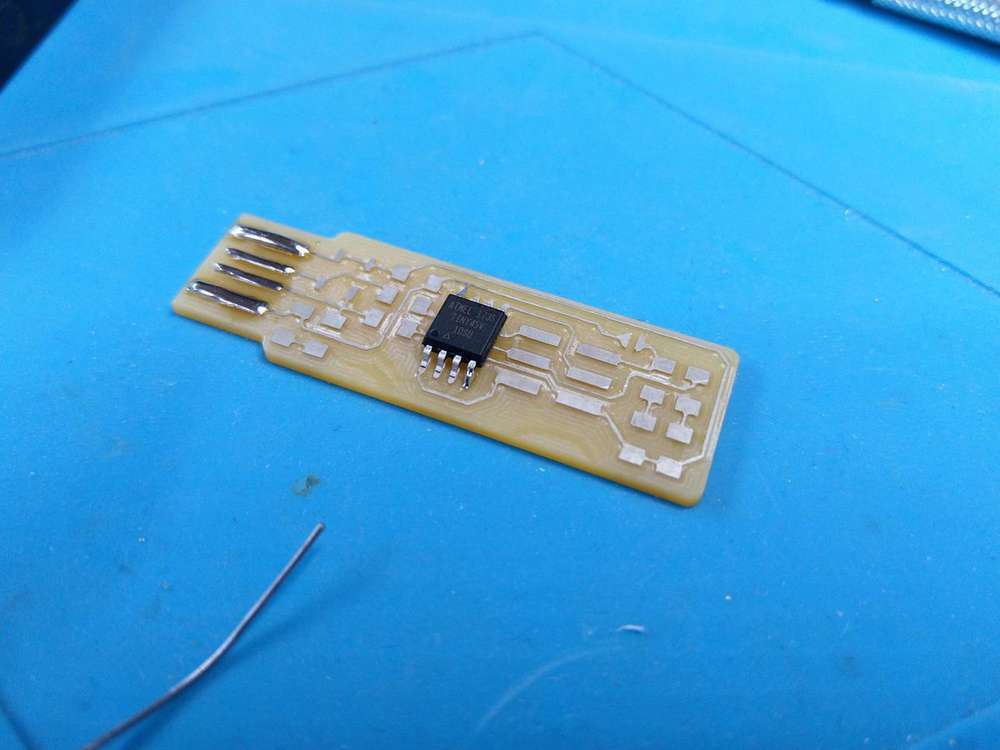
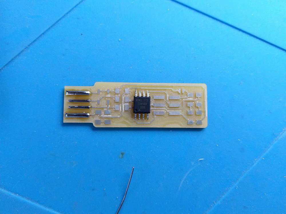
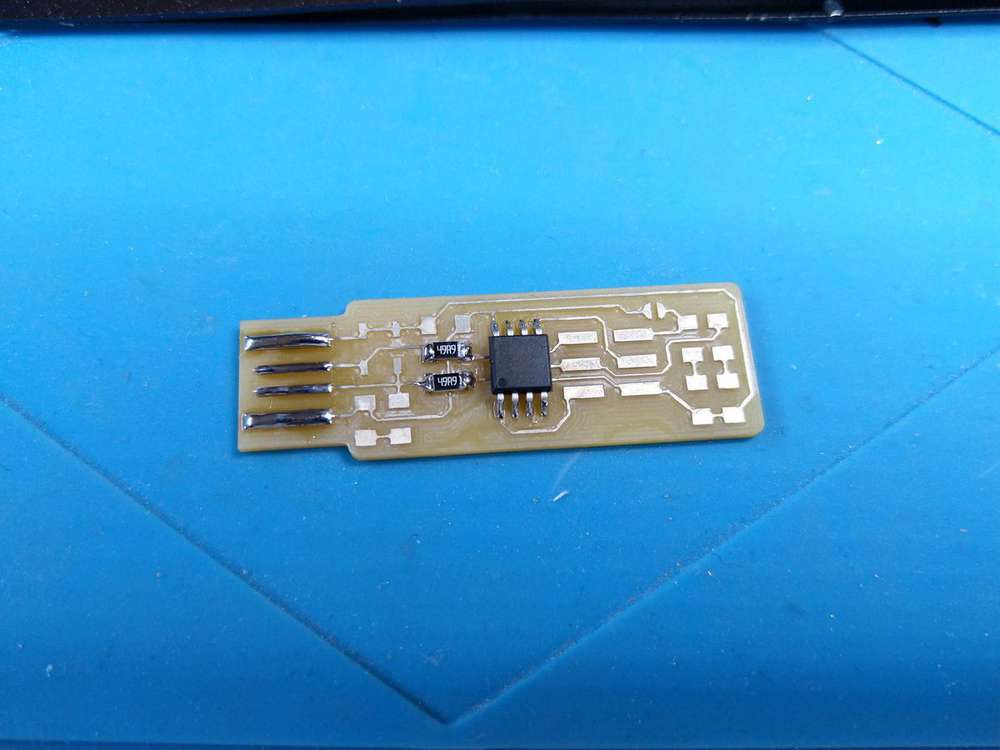
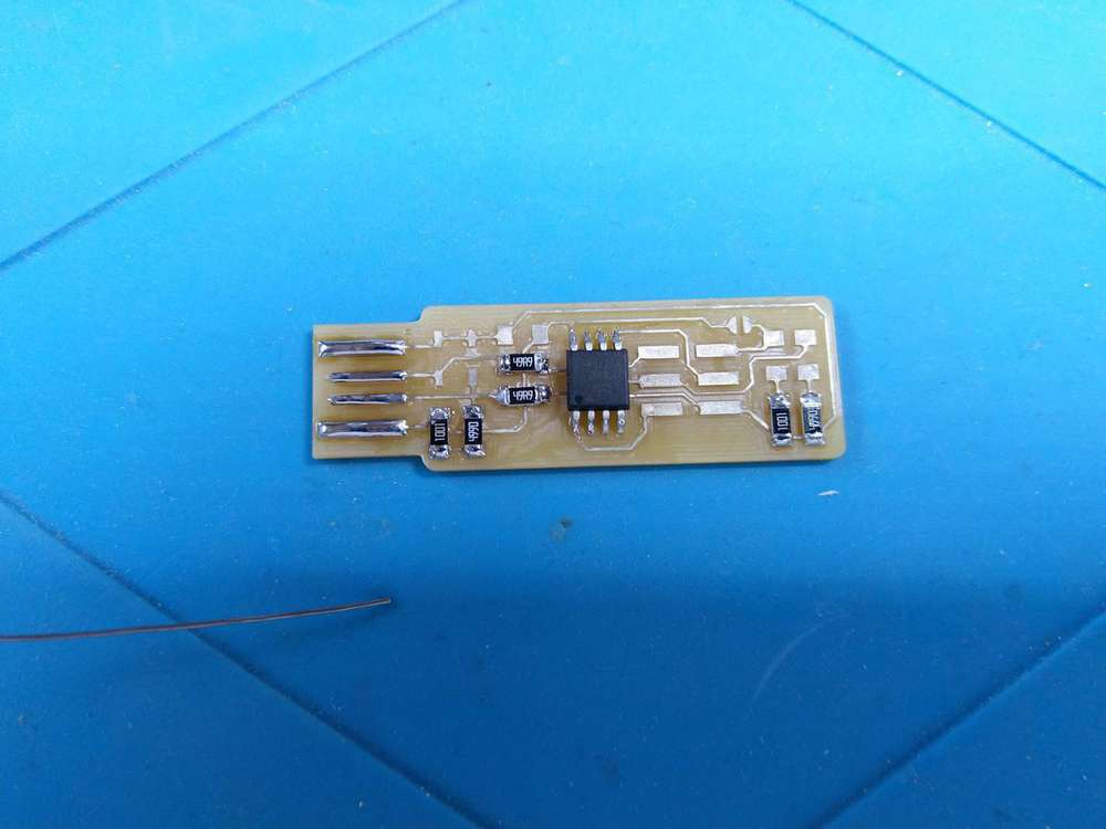
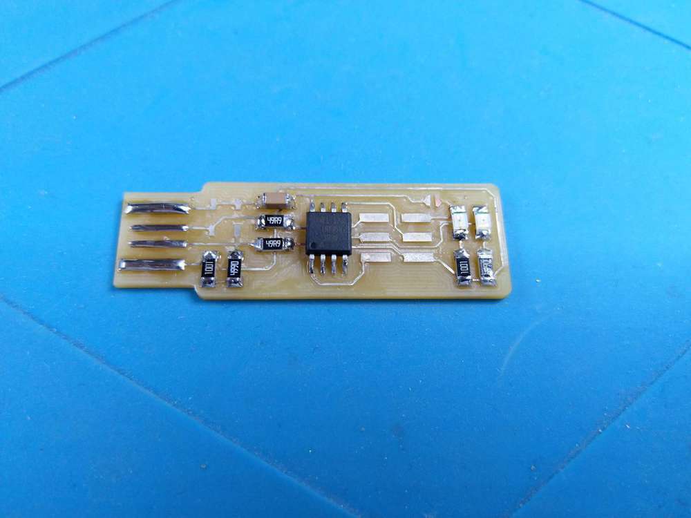
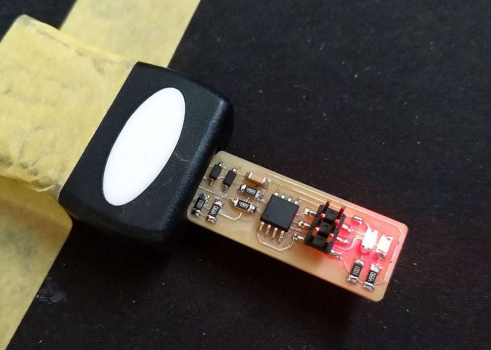
Solder the other components
After the ATtiny45, I’ve solder the other components and I’ve solder the connector in last.
| Resistors | Resistors | LEDs and capacitor | Diode and connector |
|---|---|---|---|
 |
 |
 |
 |
Testing
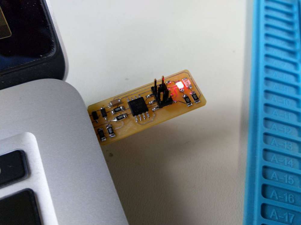
First test, I’ve checked the continuity of the traces and it feels good so I put it on my USB port and the LED turned red  So now I have to program it.
Programing :
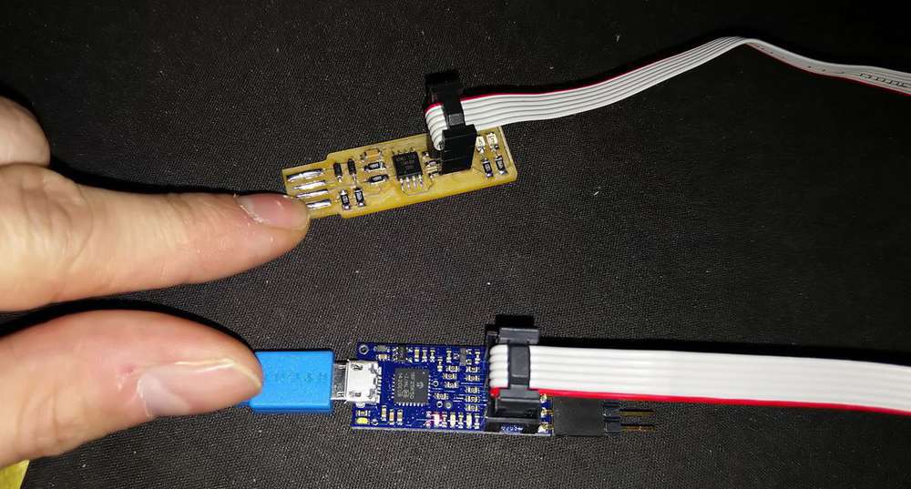
To program the board, I will use an USB extension tapped onto my desktop and the Pololu USB AVR Programmer v2.
| My board with the usb extension | My board connected to the Pololu USB AVR Programmer v2 |
|---|---|
 |
 |
First, I try the command make but it didn’t works and I got the following error :
avr-gcc: No such file or directory
So I installed the GNU AVR Toolchain with homebrew, following this link : https://github.com/osx-cross/homebrew-avr.
brew tap osx-cross/avr
brew install avr-gcc
But still an error :
make: avrdude: No such file or directory
So, I try this procedure : http://www.ladyada.net/learn/avr/setup-mac.html and after that, my command make worked and the .hex file was generated. So I tried a make flash but I got the following error :
Error: Could not find USBtiny device (0x1781/0xc9f)
So I took a look to the makefile and discover that my Pololu USB AVR Programmer v2 were not recognized. So, I make my own command line because the programming port of my Pololu USB AVR Programmer v2 is always the same : /dev/cu.usbmodem001950102
avrdude -p attiny45 -c avrisp2 -P /dev/cu.usbmodem001950102 -U flash:w:fts_firmware.hex
And it works. So, with the same idea, I set the fuses with this CL :
avrdude -p attiny45 -c avrisp2 -P /dev/cu.usbmodem001950102 -U lfuse:w:0xE1:m -U hfuse:w:0xDD:m -U efuse:w:0xFF:m
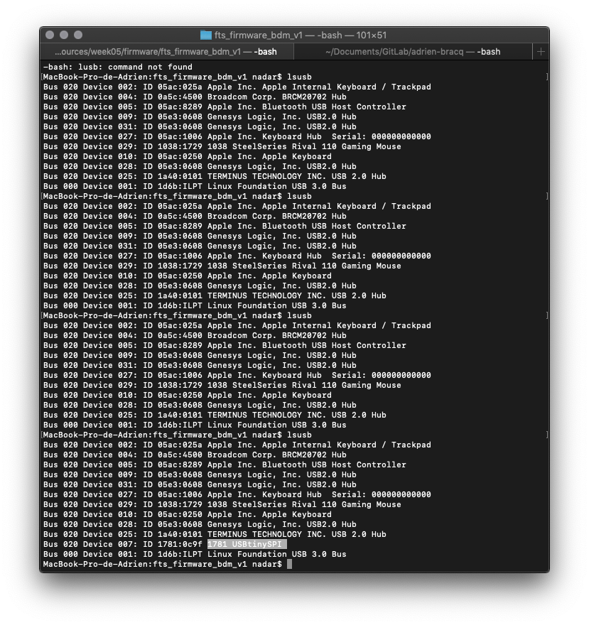
It works but I didn’t manage to find the board into the usb list of MacOs after that. So I installed lusb which is the equivalent of lsusb on linux. So, when I use the CL lsusb the terminal show me a list of all the USB port plug into my MAC.
Unfortunately, the device didn’t appear in the list. So I double check the connexion and the continuity but it was OK. So the last thing to try is to put some tap under the board to have best connexion with the USB port.
And it finally works ! It’s here ! Look :
Me in the lab after that :

So now, last step, I’ve got to blow the reset fuse. To do that, I used this CL :
avrdude -p attiny45 -c avrisp2 -P /dev/cu.usbmodem001950102 -U lfuse:w:0xE1:m -U hfuse:w:0x5D:m -U efuse:w:0xFF:m
I disconnected the Vcc from Vprog pin by removing the bridge on the solder jumper. And that’s all !! After that I’ve just checked that the board is still recognized by my computer with lsusb
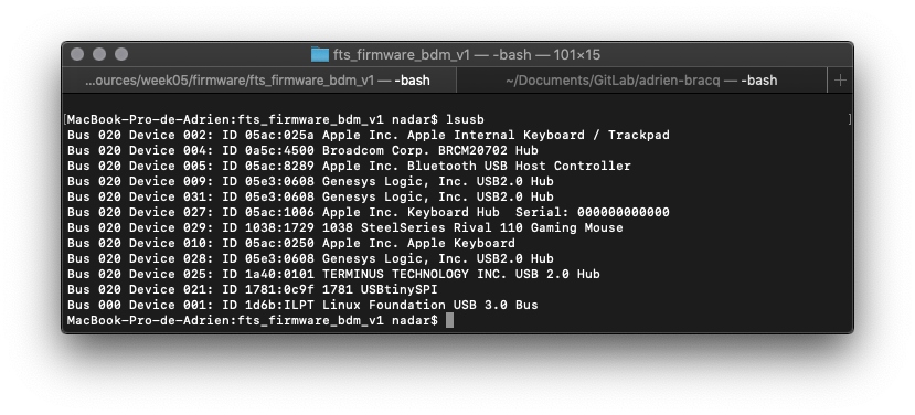