15. Mechanical design
1. Assignments :
- Document your individual contribution.
Learning outcomes :
- Work and communicate effectively in a team and independently
- Design, plan and build a system
- Analyse and solve technical problems
- Recognise opportunities for improvements in the design
Have you?
- Explained your individual contribution to this project on your own website
- Outlined problems and how you fixed them
- Included design files (or linked to where they are located) and original code
2. Project
2.1 Presentation
For this week we decide to make a badge dispenser for a comic salon in Amiens in June. The badge are mettalic and will be placed into a receptacle shaped like a funnel inside the dispenser. When it will be activated, the dispenser has to take a badge and give it to the children  .
.
On this project I’m in charge of the mecanism that will take the badge and throw it into a receptacle of the machine.
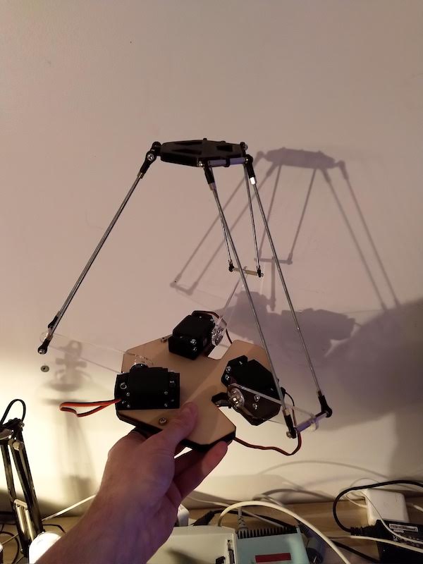
To do that, instead of a traditionnal 2/3 axis cartesian machine, I would like to create a delta robot like the one you can find on the industries for pick place or food industries. As the badge are very light, the delta robot will work fine and it also will be very fun to design and use.
2.2 Work in team
To work with the other members of my team, we have a basecamp project that will be used to exchange informations and discuss when we are not in the same places.
We also setup a project into fusion 360 so every body have access to the 3D files of each other, and we can work on our part and assemble them together.
3. Designing the machine
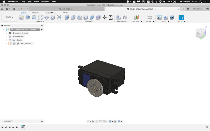
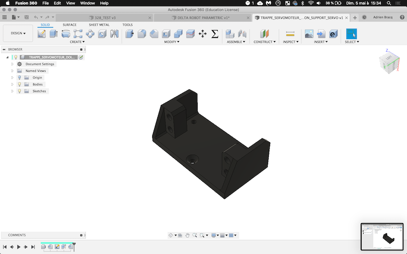
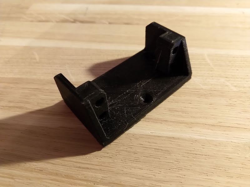
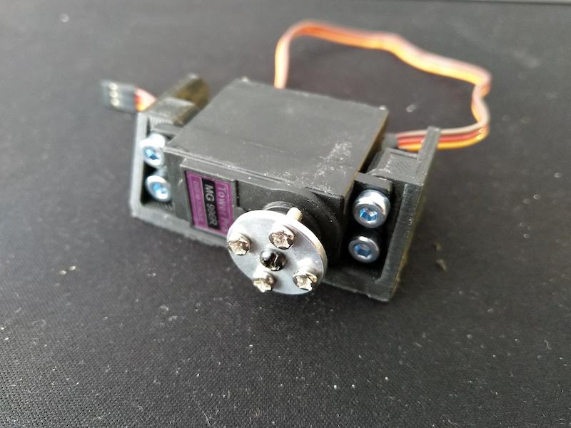
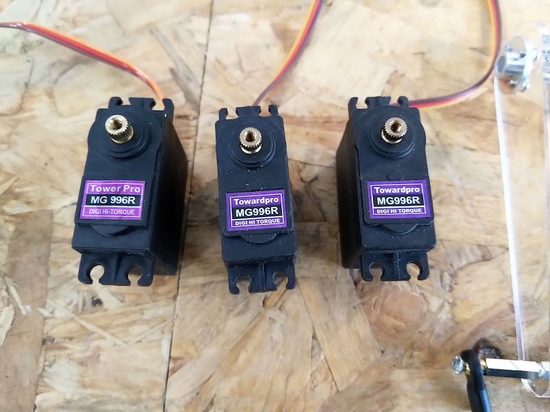
So, I Fusion 360, I first design the servomotor I will use : towerPro 996R., and I designed the servomotor support that I will 3D print.
| Servomotor | Support |
|---|---|
 |
 |
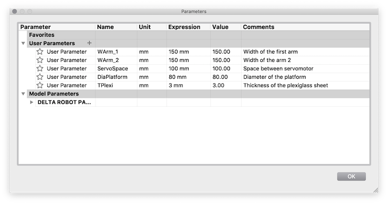
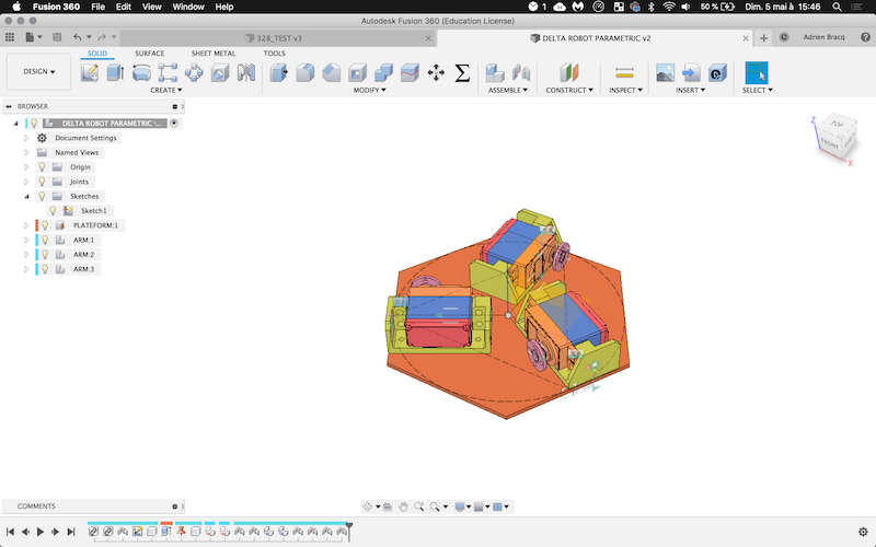
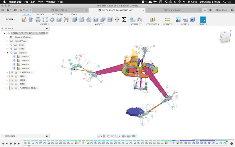
As I know that I will have to make a lot of modifications on the dimensions of the robot, I made it parametrical at the beginning :
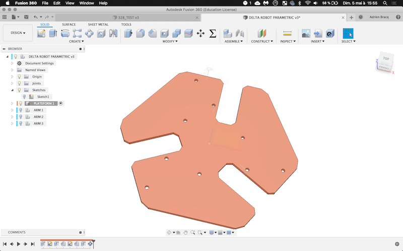
After that, I import the two previous parts created, and assembled them into a file. I created a component for each arm and create the main platform. I created the first arm and the notches on the platform.
| Platform | Arms | Notches | Notches and holes |
|---|---|---|---|
 |
 |
 |
 |
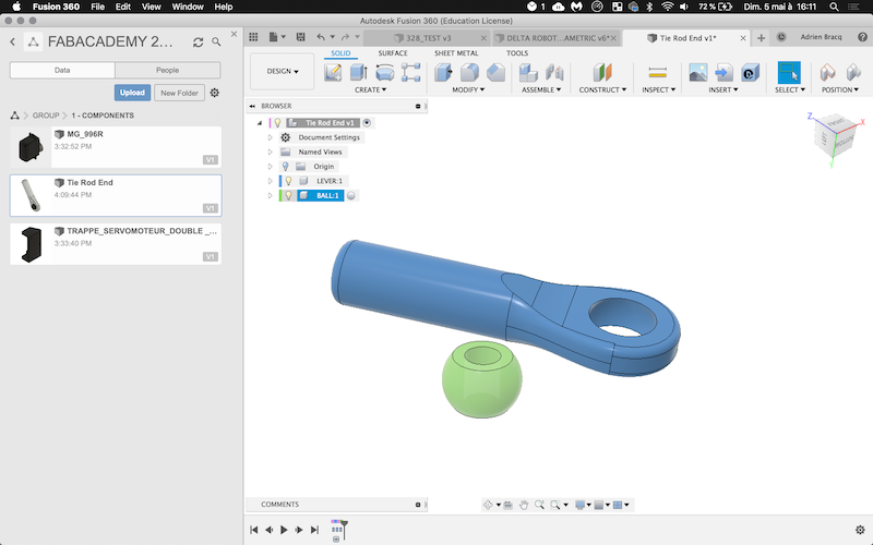
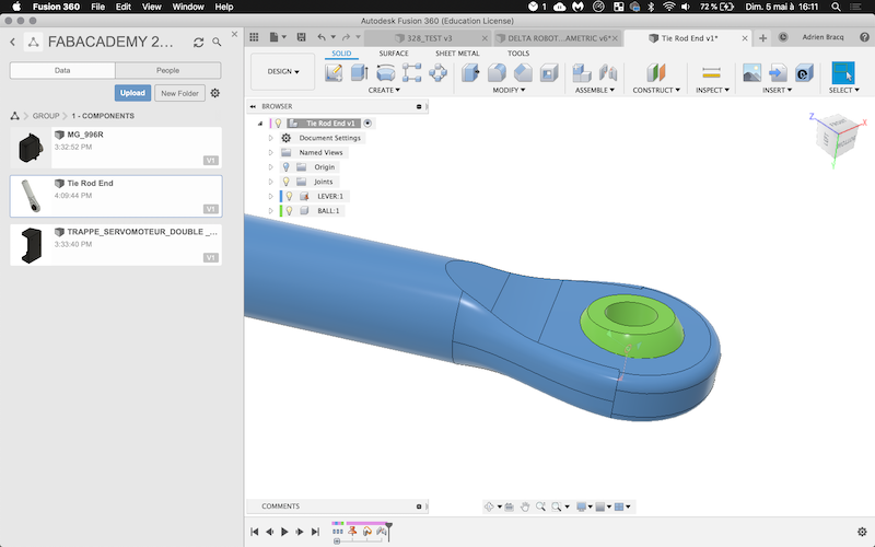
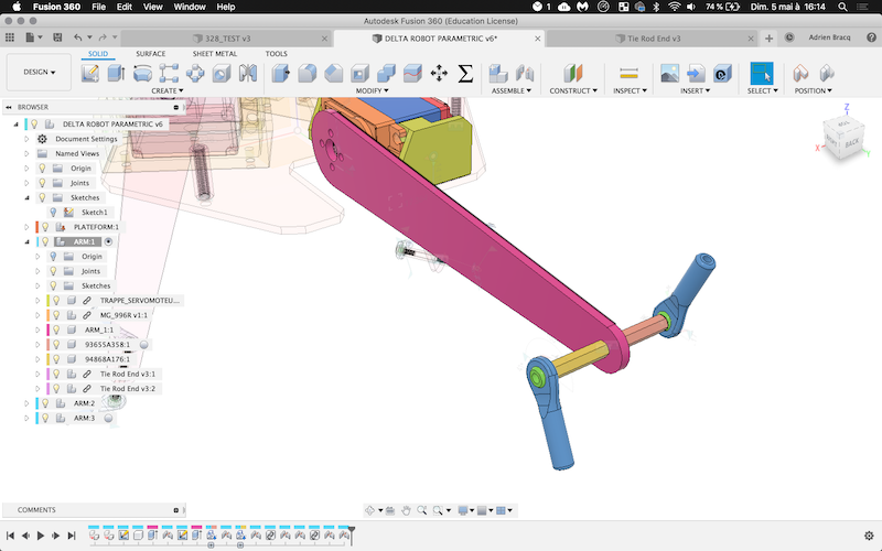
Now that I have the first arm, I need to design the second arm. To do that I have to create the RC tie rod lever of 3 mmm that I will use in my design :
| Tie rod | Assembled with ball join | Assembled on the arm |
|---|---|---|
 |
 |
 |
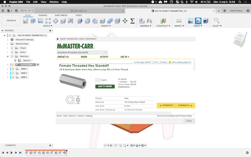
Note
To integrate screw or threaded standoff, I didn’t created them but I imported them into my design using the McMaster-Carr plugin inside Fusion 360
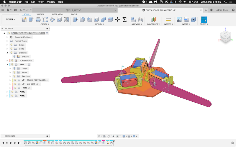
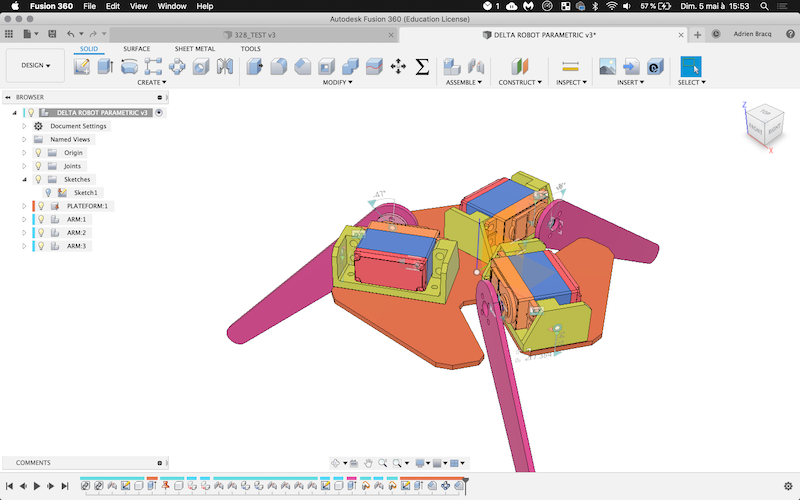
By creating all the join on the design, I’ve got a lot of issues. I think Fusion360 didn’t like a lot ball join on this design … And I din’t manage to make a clean assembled of my design for the moment …
| All the join | The delta bot assembled but … a little bit “twisted” … |
|---|---|
 |
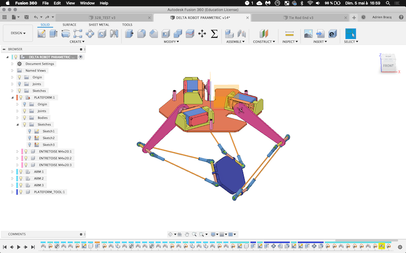 |
You can find the 3D design below and you can download all the file below :
4. Making parts
4.1 Printing
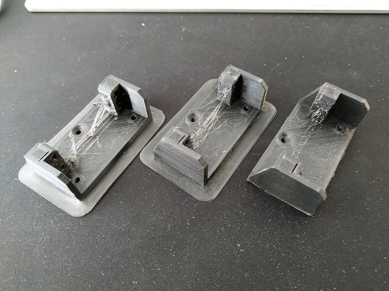
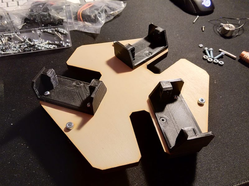
On this project, 2 parts has to be 3D printed : - The main platform - The servomotor support
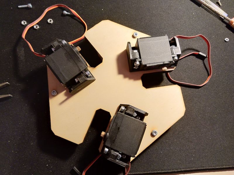
| The servomotor support printed | 3 support printed | Testing the servomotor inside it’s support |
|---|---|---|
 |
 |
 |
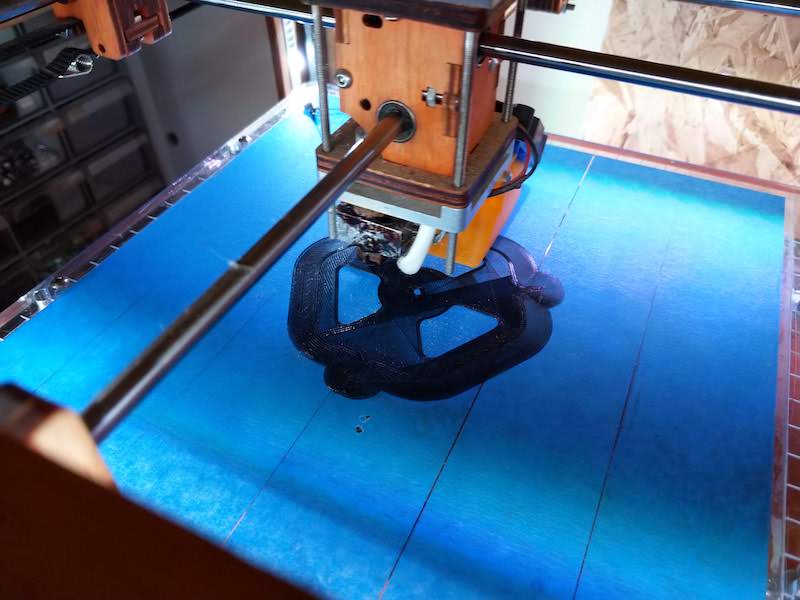
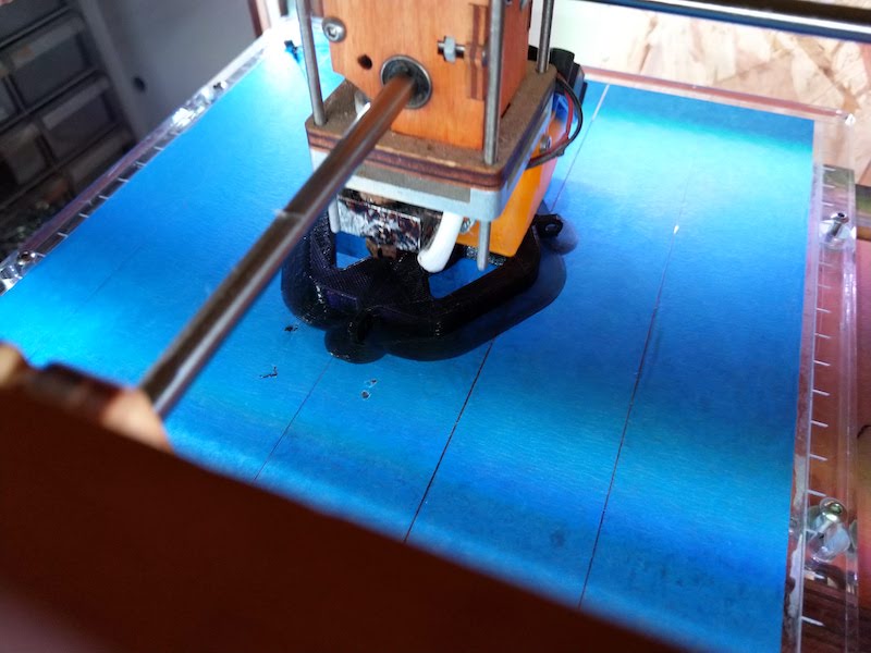
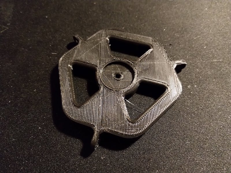
The main platform has been also 3D printed has you can see below :
| Printing the platform | Printing the platform | The platform |
|---|---|---|
 |
 |
 |
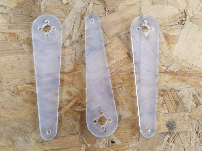
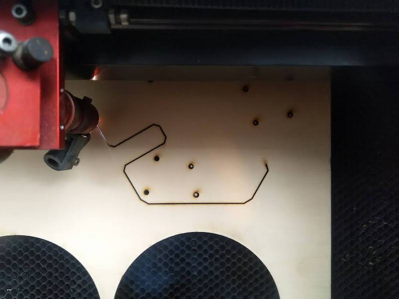
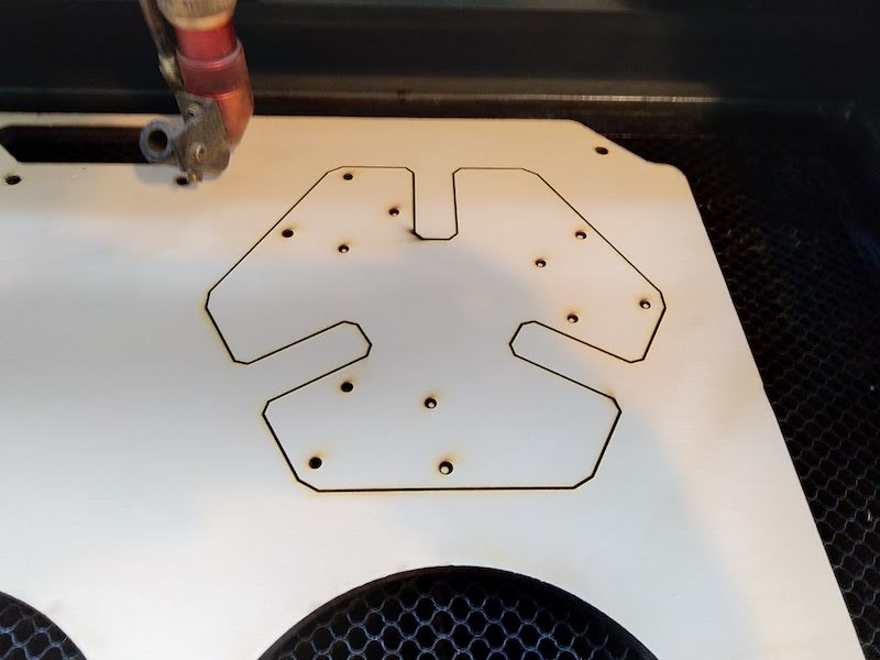
4.2 Laser cutting
The arms has been cut into a 4mm acrylic sheet and the base into a 10mm wood sheet.
| Cutting the arms | The arms | Cutting the base | The base |
|---|---|---|---|
 |
 |
 |
 |
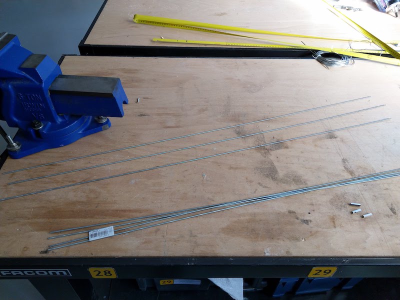
4.3 Hand making
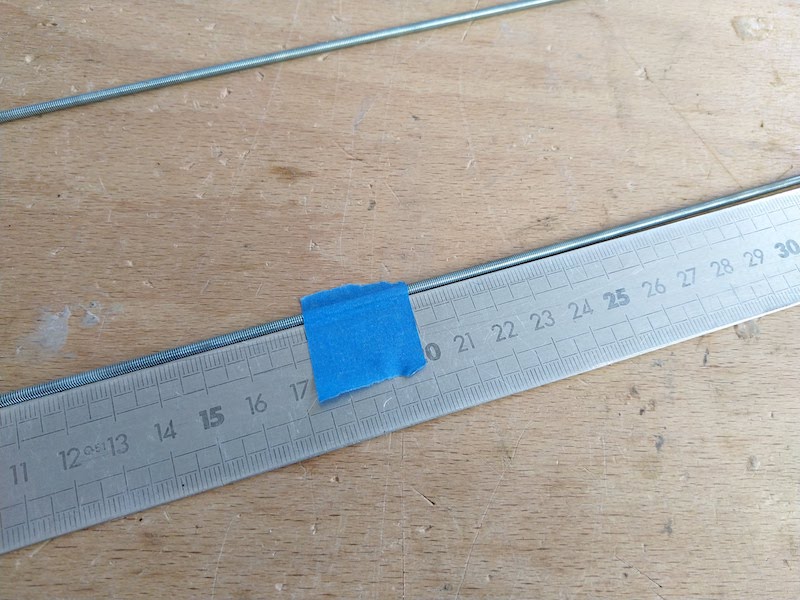
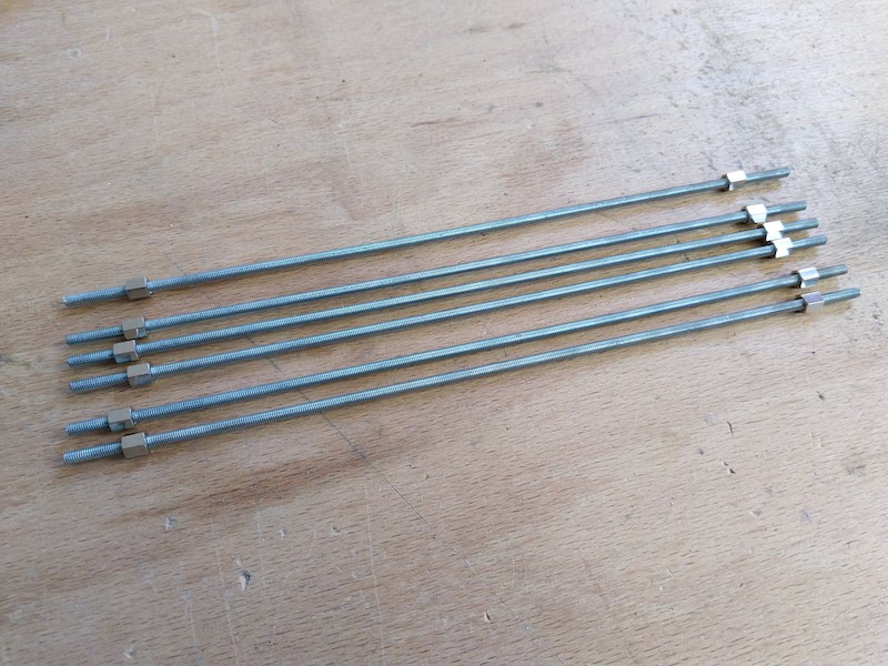
To make the rod, I use 3mm threaded rods cutted to 200mm long. I cut them with a hacksaw and use 10mm spacer on them.
| The threaded rods | Measuring the rods | All the rods |
|---|---|---|
 |
 |
 |
5. Assembling the robot
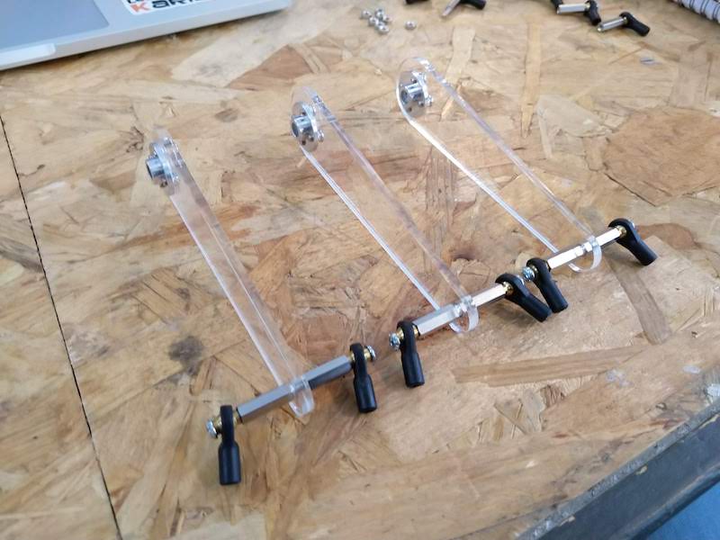
5.1 Assembling the arms :
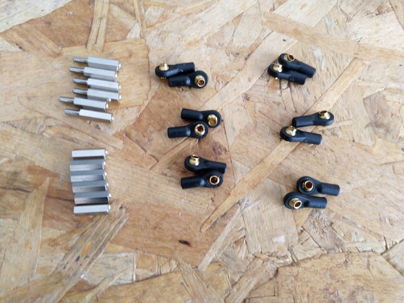
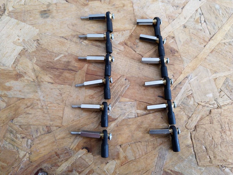
First, I assembled the three arms with the part made before :
| The ball join | Assembly the ball join and the spacers | Add the acrylic arms |
|---|---|---|
 |
 |
 |
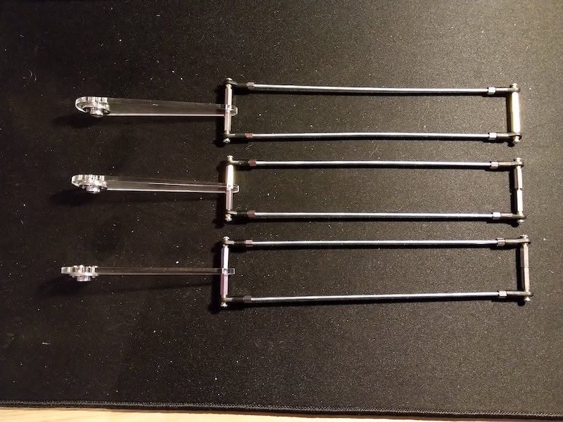
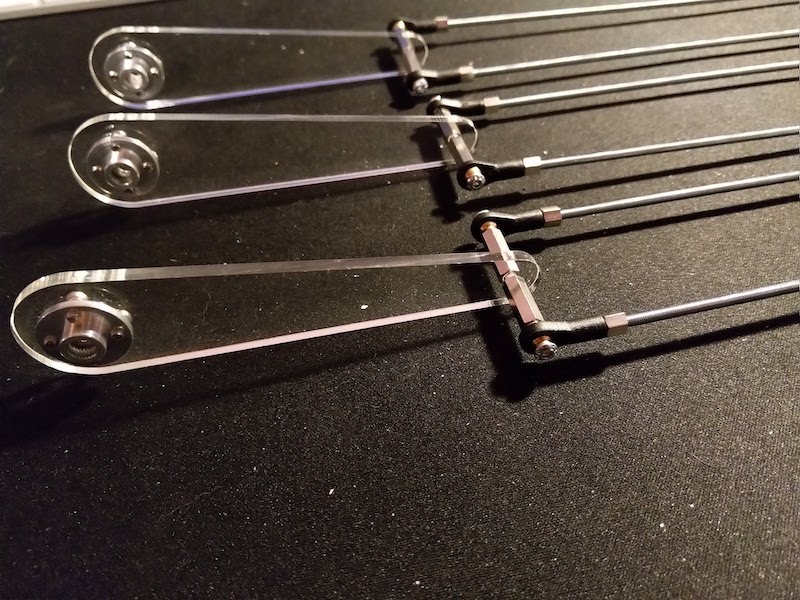
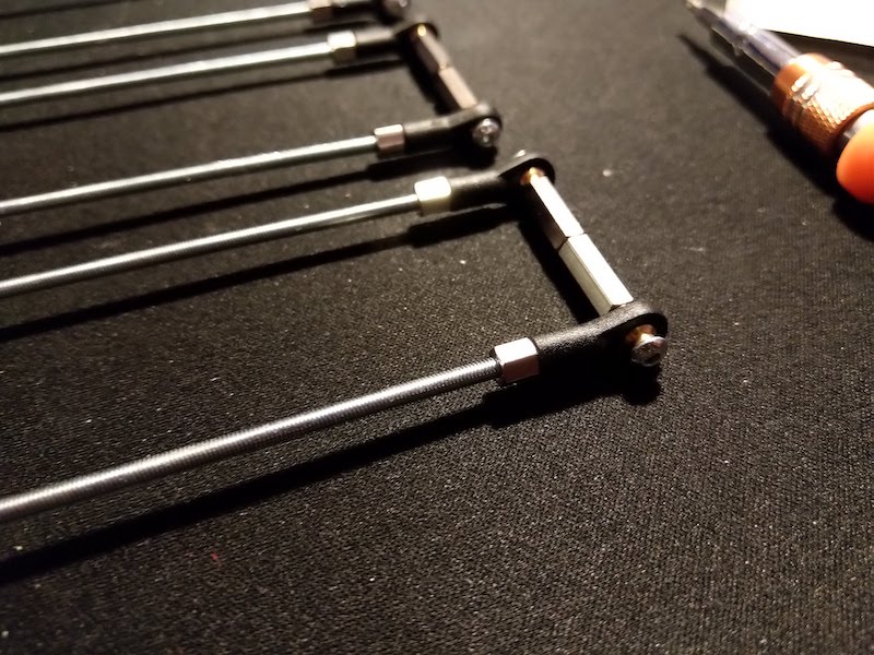
| Add the threaded rods | View of the first arm | View of the end of the rods |
|---|---|---|
 |
 |
 |
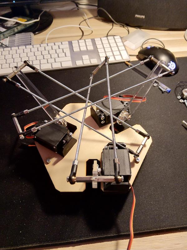
5.2 Assembling the delta
Now it’s time to assemble the robot :
| The Servomotors | Base with the support | Add the servomotors | Add the arms |
|---|---|---|---|
 |
 |
 |
 |