11. Input devices
1. Assignments
- Described your design and fabrication process using words/images/screenshots or linked to previous examples.
- Explained the programming process/es you used and how the microcontroller datasheet helped you.
- Explained problems and how you fixed them
- Included original design files and code
2. Project :
For this assignment I choose to work on a hall sensor which could be use for my final project. During week 7 “Electronic design”, I’ve made a PCB with some input and output on it. I’ve the emplacement for a hall sensor, but I didn’t solder it this week.
So, this week, I had to :
- Solder the sensor
- Test it
- Write a program to test the readings
- Test the functionalities of the datasheet
- Debug if there are some issues
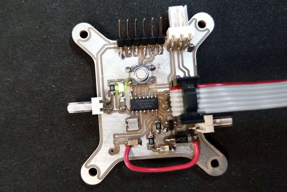
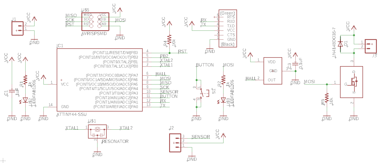
3. The board :
As explained before, this week I’ve used the previous board designed during week 7 “Electronic design”. You can have more informations about it following the link on the left side.
Just as a remember :
| The board | The schematic |
|---|---|
 |
 |
I use a ATTiny44 for this board. SpenceKonde made a great pin mapping cheat sheet for the attiny44 on GitHub as you can see below :
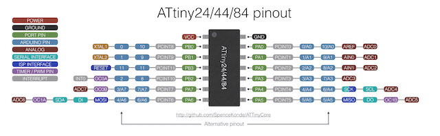
As I didn’t manage to make my board working with PlatformIO, I will use C++ with Arduino for the moment. So, In that condition, the pin mapping for my board is the following :
| Function | Pin |
|---|---|
| Button | 2 |
| External Sensor | 3 ou A3 |
| Hall Sensor | A7 |
| Mosfet ( Motor ) | 6 ( PWM ) |
| Led | 6 ( PWM ) |
| RX | 0 |
| RX | 1 |
4. The sensor
4.1 Presentation :
I used a hall sensor A 1324LLHLT. It’s a low noise linear hall sensor with an analog output. I used the SOT23-W package for my board.
4.2 Schematic and board
To make my schematic, I used the datasheet of the component, and especially two sections :
| Pin-Out Diagrams | The typical application circuit |
|---|---|
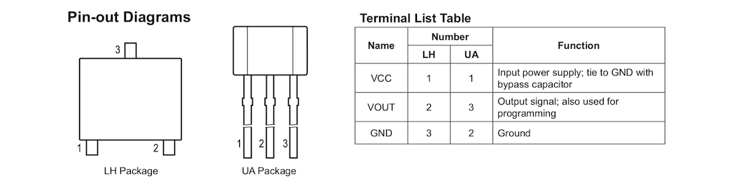 |
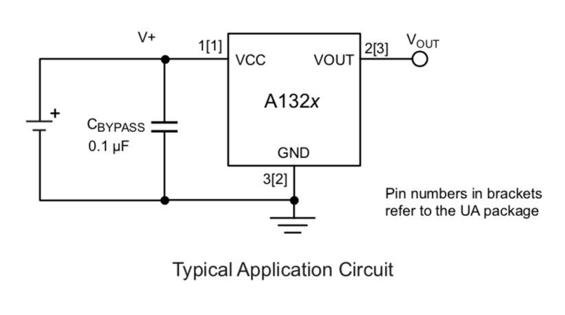 |
As we can see, the sensor need a 0,1uF capacitor to work well, between the VCC and the GND. That’s what I’ve done on my board. The sensor is also plug to a analog pin so you can detect the variation of the sensor.
Warning
Some component have different supply voltage. It’s common to have sensor whiwh has to be supplied in 5V but also in 3V. You can check this specification into the datasheet. You should have inside a table with the Operating characteristics.
In our case, the supply voltage of our sensor is between 4,5V and 5,5V with a typical supply voltage to 5V.
Remember to always check the datasheet before making a board with a component.
4.3 Some interesting features and characteristics
Reading the datasheet, I saw some interesting features that I would like to test :
There is an output saturation voltage that can be achieved by putting a pulldown or a pullup resistor. As the ATTiny have internal Pullup that can be activate, It could be interesting to test it. Why ? - For my use in the final projet, I just need an TOR signal - Reading a digital signal is quicker than reading an analog one - We can easily change the operation mode without changing the circuit
There is a Power-On Time. Below this time the sensor will not be ready for reading. It’s about 32us. I had to keep it in mind if I want an effective software.
The chopping frequency (fc) is 400kHz, which means that I can read 400 000 time the sensor during one second. Or in other terms, the time between two readings cannot be less than 0,0000025 seconds, so 2,5uS . The datasheet also notice that “fC varies up to approximately ±20% over the full operating ambient temperature range and process.”. So in worst case, the sensor can only assumed a 320 kHz frequency, so a time between two reading of about 3,125 uS.
The last characteristics is very interesting in my case because I would like to use the sensor to control the speed of the rotation of my beacon. So let’s do some math to check if the sensor is correct for my use : if I have a magnet on the disk of my beacon in rotation, what max speed can I measure ?
As I can make one turn in 3,125uS max, I can achieved a speed rotation of about 320 000 turns by seconds  I think it will be enough …
5. Software
5.1 Testing the sensor ( analog )
To test the sensor, I will just read it and send the value to my serial port. I used the program below :
#include <SoftwareSerial.h>

SoftwareSerial mySerial(0, 1); // RX, TX

void setup()
{
  mySerial.begin(4800);
}

void loop()
{
  mySerial.print("Value :");
  mySerial.println(analogRead(A7));
  delay(250);
}
Note
I used a 250 millisecond delay between each read so I can see the value correctly on the serial port.
Results and conclusions :
When I put a magnet on the sensor, I see that the values are changing between approximatively 1000 and 1. When there is not magnet, the value is at about 500.
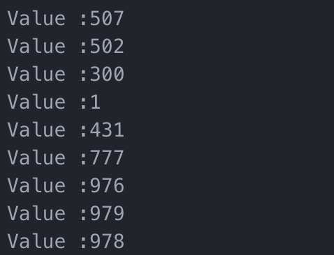
For the moment, it’s totally logical and in line with the datasheet and the components :
- The Attiny have an analog resolution of 8bit ( 1024 ) so, the reading cannot exceed 1024 when the sensor reach 5V.
- The Sensor is linear between 0 and the supply voltage ( 5V )
- The sensor feature a quiescent voltage output of 50% of the supply voltage, so, when there is nothing on it, the output value will be 2,5V approximately. In 8bit, throw the analog reading, you should have 1024/2 = 512.
5.2 Testing the sensor ( digital )
Now testing it in digital mode with the internal pullup activate :
#include <SoftwareSerial.h>

SoftwareSerial mySerial(0, 1); // RX, TX

const int hallSensor = 7;

void setup()
{
  mySerial.begin(4800);
  pinMode(INPUT_PULLUP,hallSensor);
}

void loop()
{
  mySerial.print("Value :");
  mySerial.println(digitalRead(hallSensor));
  delay(250);
}
Results :
And when I test it, the result was completely different from what I was thinking about !
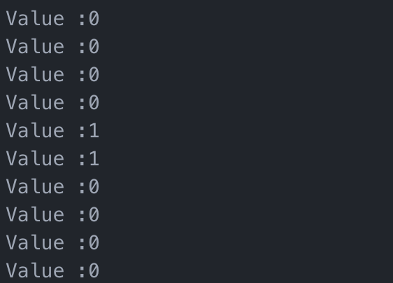
What I expected : The value will change from 0 to 1 if the magnet is here or not.
What happened : The value change from 0 to 1 when you change the magnetic pole of the magnet !
Conclusion :
The digital way is very interesting for me and the way the sensor change its output with the magnetic pole can help me a lot to measure the speed. I can imagine putting more than one sensor with an alternance of magnetic pole, to measure speed with a higher efficency. I will definitively use this way for the rest of my experimentations.
5.3 Measure time to measure speed
To measure speed, I need to measure the time between two readings. I will use the digital way here, and I will measure the time between two change of magnetic pole, assuming that I have only two magnet.
To measure time, I will use the micros() function which calculate the elapsed time in microseconds since the power on of the microcontroller.
#include <SoftwareSerial.h>

SoftwareSerial mySerial(0, 1); // RX, TX

const int hallSensor = 7;
unsigned long elapsedTime = 0;
bool control = 0;

void setup()
{
  mySerial.begin(4800);
  pinMode(INPUT_PULLUP,hallSensor);
}

void loop()
{
  bool sensorState = digitalRead(hallSensor);
  if ( sensorState && control )
  {
    elapsedTime = micros();
    control = false;
  }
  if ( !sensorState && !control )
  {
    elapsedTime = micros() - elapsedTime;
    control = true;
    mySerial.print("Time :");
    mySerial.print(elapsedTime);
    mySerial.println(" uS");
  }
}
Results :
It works great and send me the elapsed time between each change of magnetic pole.

Conclusions :
So now, by knowing the diameter of the spinning disk where the magnets are placed, I can know the rotating speed of the disk and adjust the speed of the motor proportionally.
6. Next Steps :
During the next week, the assignments will be about output device. So the idea for next week is to use the previous code in complement with the driving of a motor and try to adjust speed.