Parts
Operating principle
To explain how the project work, I decided to make a simplify drawing of the main parts :
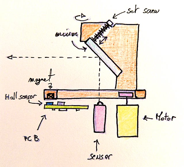
As you can see on the drawing, there are 4 main parts :
- The mirror support (orange)
- The motorization - Motor + wheel (yellow and pink)
- The PCB (green)
- The sensor (purple)
The parts that I didn’t represent are the following :
- The main support
- The Shell
- little mechanical parts like bearing, screw and other …
Processes that will be used
At the beginning I planned to do the following part using some process. I add into the table a percentage of sureness, because I know that when I will design the parts, I may find other way to do my parts.
| Parts | Planned process | Sureness (%) | Further information |
|---|---|---|---|
| The mirror support | 3D printing | 80% | Maybe some parts of the support will be done by laser cutting |
| Motor wheel | Molding and casting | 80% | Mold will be done by 3D printing and or lathing |
| PCB | Milling | 100% | The PCB will be milled, but I also would like to test PCB production by SeeedFusion |
| Main support | 3D printing / laser cutting | 60% | I’ve not designed the parts in my head for the moment, but I think it will be an assembled of several parts |
| Shell | 3D printing / laser cutting | 80% |
Description of the parts
Mirror support
The mirror support will be a key part because it will be the rotating part and also the support for the tricky part : the mirror  ! At first, I draw it as you can see below :
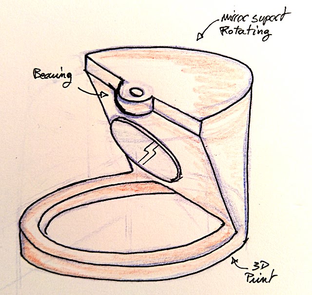
I was not happy with this solution. Specially because I find it ugly and massive. So, during the process of 3D design a decided to redraw it completly.
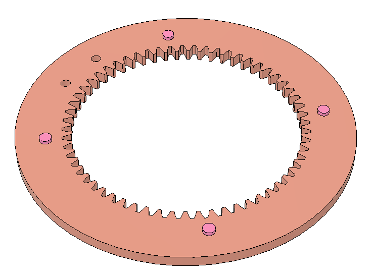
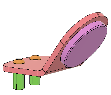
So now the support is a two parts component made by laser cutting 3mm PMMA :
| The ring | The mirror support | The complete support |
|---|---|---|
 |
 |
 |
As you can see, the mirror support is a piece of PMMA that will be bend to obtain the right angle.
The magnet are also directly implemented into the disk.
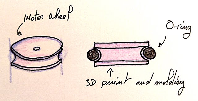
Motor support and wheel
First idea of the motor wheel :
As the mirror support is now a cylindrical gear, I need to change the design of the motor wheel. It’s now a gear that will be 3D Printed :
| View 1 of the motor gear | View 2 of the motor gear |
|---|---|
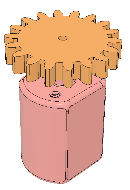 |
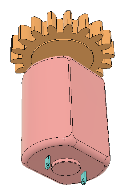 |
I also designed a support for the motor so I can adjust the pressure of the gear onto the ring.
| View 1 of the motor support | View 2 of the motor support |
|---|---|
 |
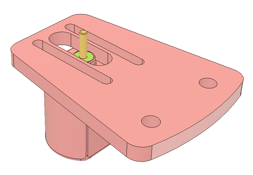 |
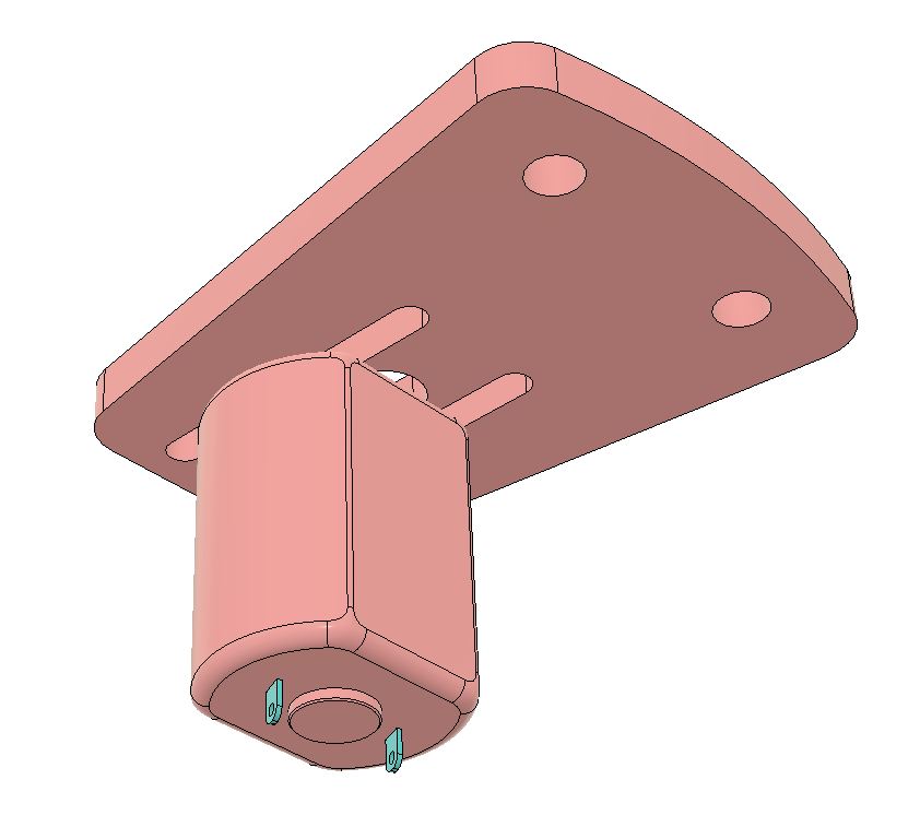
The sensor support
I design two part for the sensor support :
- The support, which will be into a piece of acrylic
- The fixation triangle that will be 3d printed
The function of this part is to maintain the reflective sensor and to be able to adjust it if necessary.
| View 1 | View 2 |
|---|---|
 |
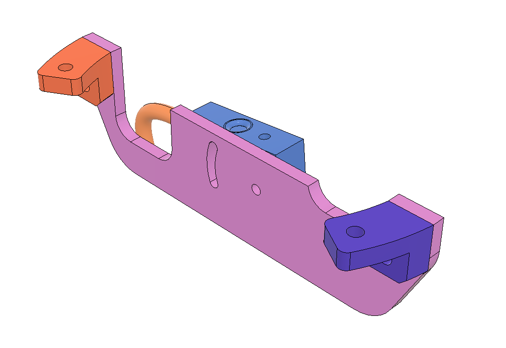 |
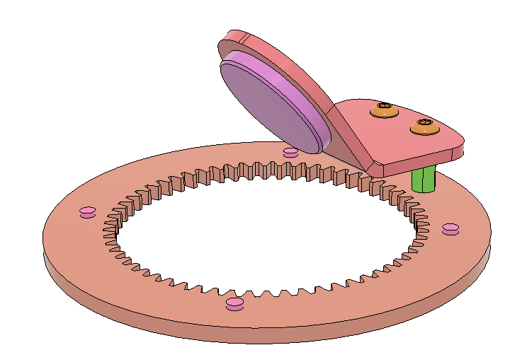
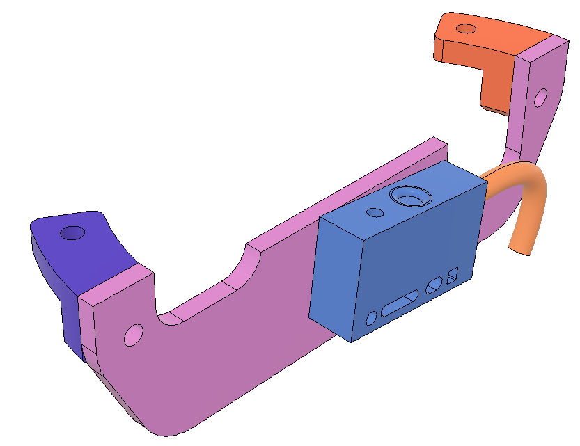
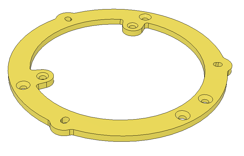
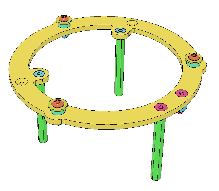
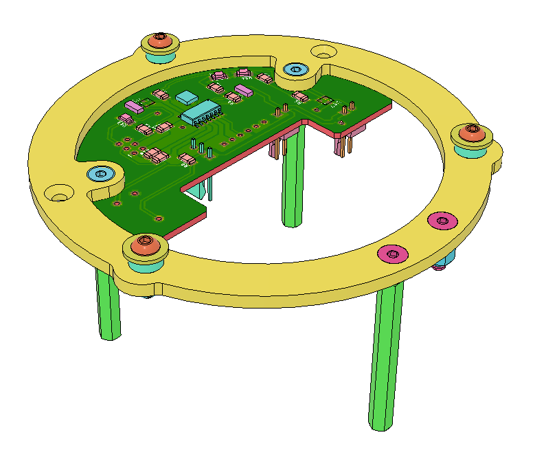
Support ring for the beacon
After that, I designed a support ring that :
- will be the support of the bearings for the rotating mirror ring
- will be used to screw the fixed parts :
- the motor support
- the sensor support
- the PCB
| Support ring | With all the screws and bearings | With the PCB |
|---|---|---|
 |
 |
 |
Shell
The first drawing of the shell was the following but as the design of the rest of the parts changed, I also changed the shell design.
Original design :
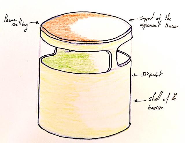
Now, there is two parts for the shell. One is 3D printed, the other is cut by laser in acrylic.
| View of the acrylic part beside | view of the shell on the top |
|---|---|
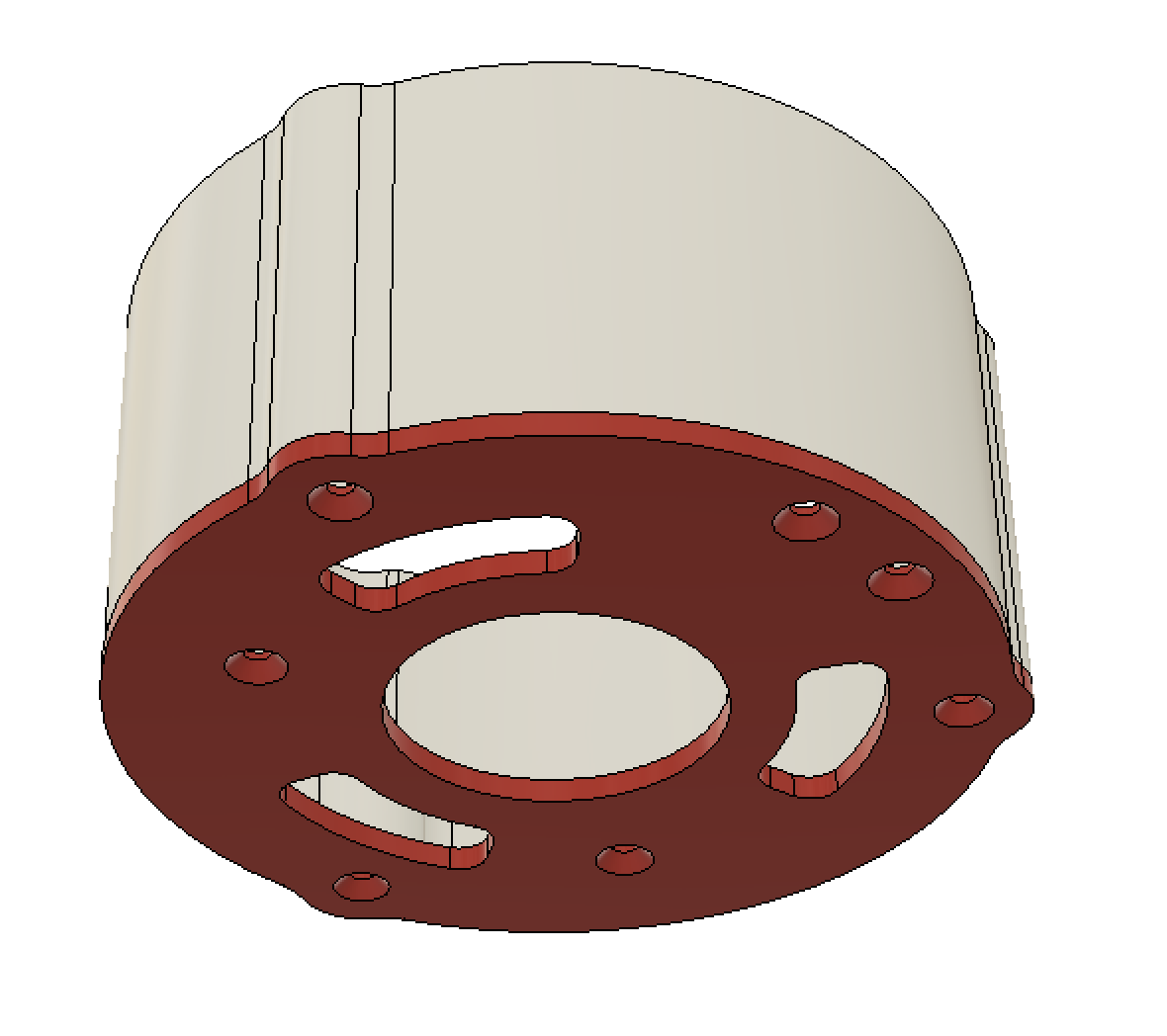 |
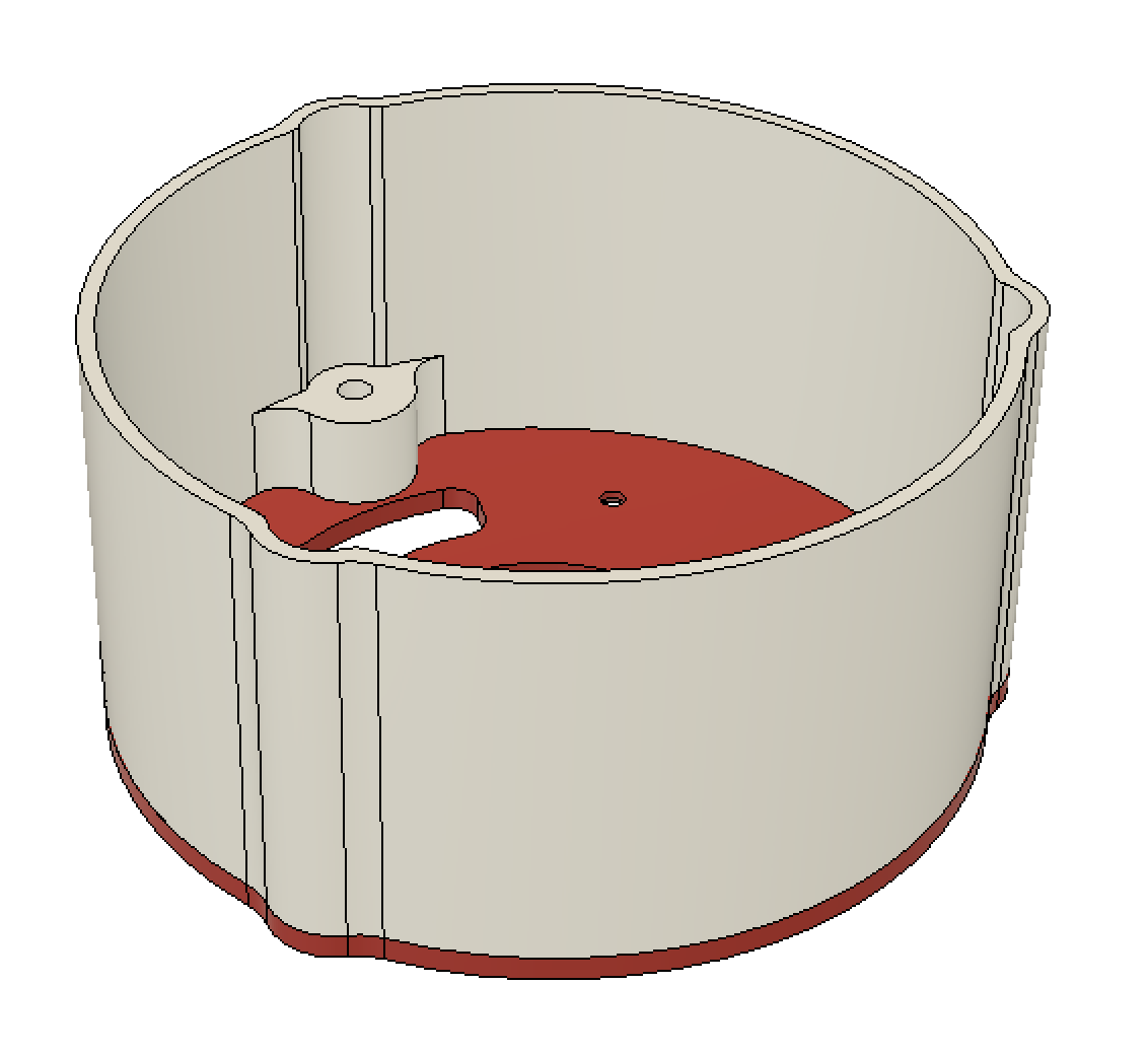 |
First 3D View
To test the project before making the different parts, I test it into Fusion360 by trying to join and move all the components. You can see it on the video below :
And here you can have the 3D view of the project :
And finally you can find the project sources following this link..
So now, next step : fabrication.