14. Networking and communications
1. Assignments :
- Design, build, and connect wired or wireless node(s) with network or bus addresses
Learning outcomes :
- Demonstrate workflows used in network design
- Implement and interpret networking protocols
Have you?
- Described your project using words/images/diagrams/schematic screenshots.
- Explained the programming process/es you used.
- Outlined problems and how you fixed them
- Included design files (or linked to where they are located) and original code
2. Project
For the previous week, I use the same PCB I’ve designed week07. But for this week, I would like to create a more complex PCB to test the following communications :
- UART ( To interface with my first board but also with my computer for week15 )
- I2C ( to interface with my robot or other PCB )
- SPI ( to interface with a LCD screen )
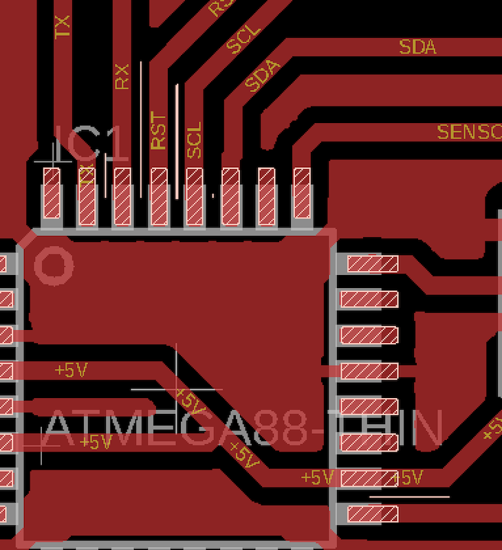
I also want to have more IO and a more powerful microcontroler. So I decided to :
- Use an Atmega328P
- Have two outputs for motor or solenoids
- Have two inputs for sensors
- Have two outputs for servomotors
- Have the possibility to separate or unified the supply for the actuators a the rest of the board.
AND : it have to be tiny and on 1 layer … Challenging 
3. Design the new board
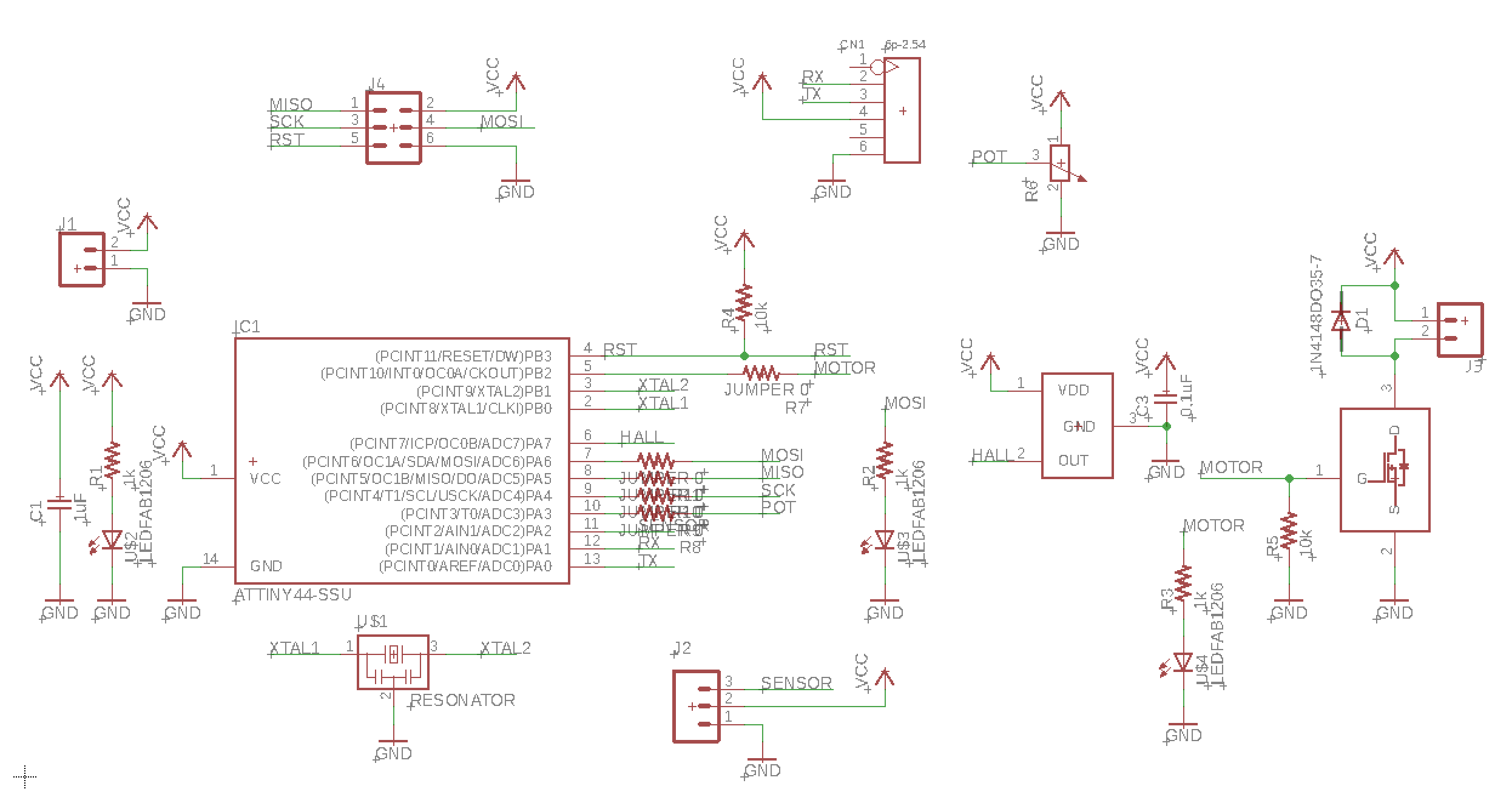
3.1 Design the Schematic
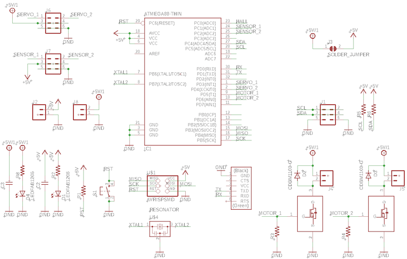
So for this board, the schematic is simple and I’ve use what I learned during the previous week, specially on week 7.
All the function are separated so you can easily distinguish all of them.
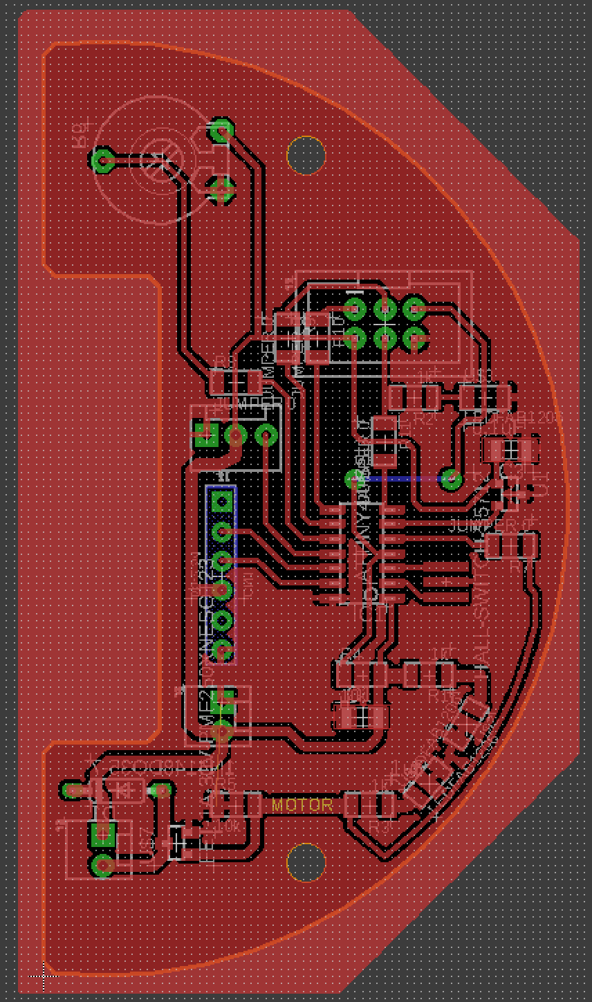
3.2 Routing the board
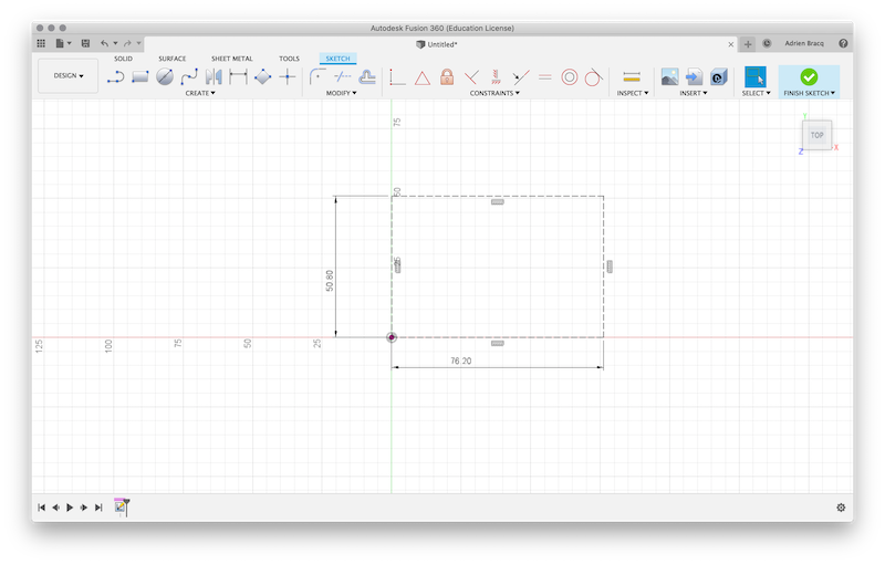
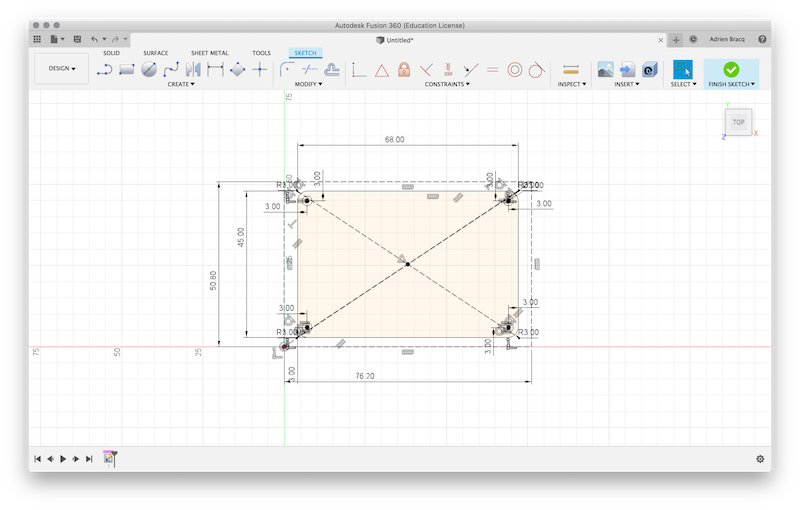
Before creating the board, I create a PCB into Fusion 360 so I was able to make my own outline design.
| The maximum size of my PCB | Creation of the outline | Creating the PCB |
|---|---|---|
 |
 |
 |
After that : - I push the modification on Eagle to have the right outline of my PCB. - I’ve created the board using the schematic. - I’ve moved the components to tidy the board and try to assemble the components by group.
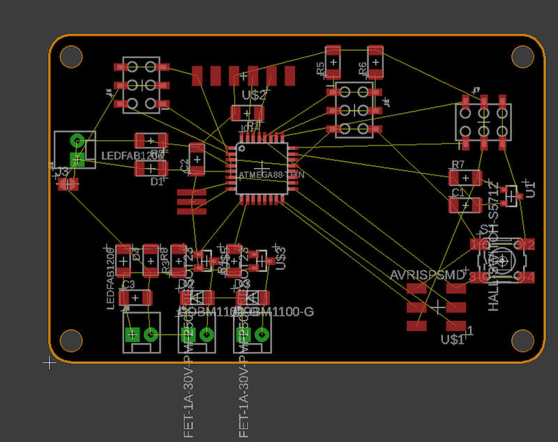
Before routing, I’ve opened the DRC menu and change the parameters so I can use a 1/64 mill bit every where. I’ve placed the added components and wire it to the more versatile pin of the Attiny.
To help me during the routing process, I’ve placed a Ground plane.
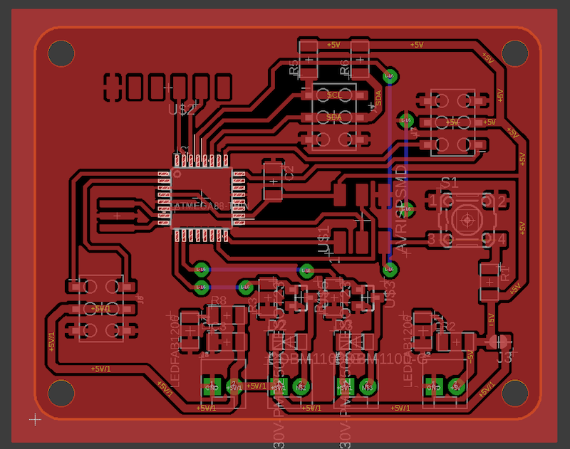
After running the DRC, I find some little issue due to the space between some wire. I correct them by locally change a bit the thickness of the wires.
You can find all the files into the sources of this week on gitLab.
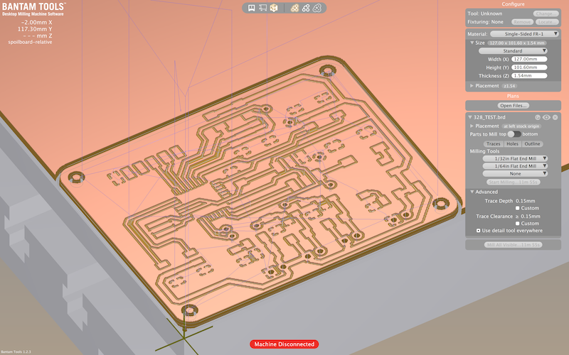
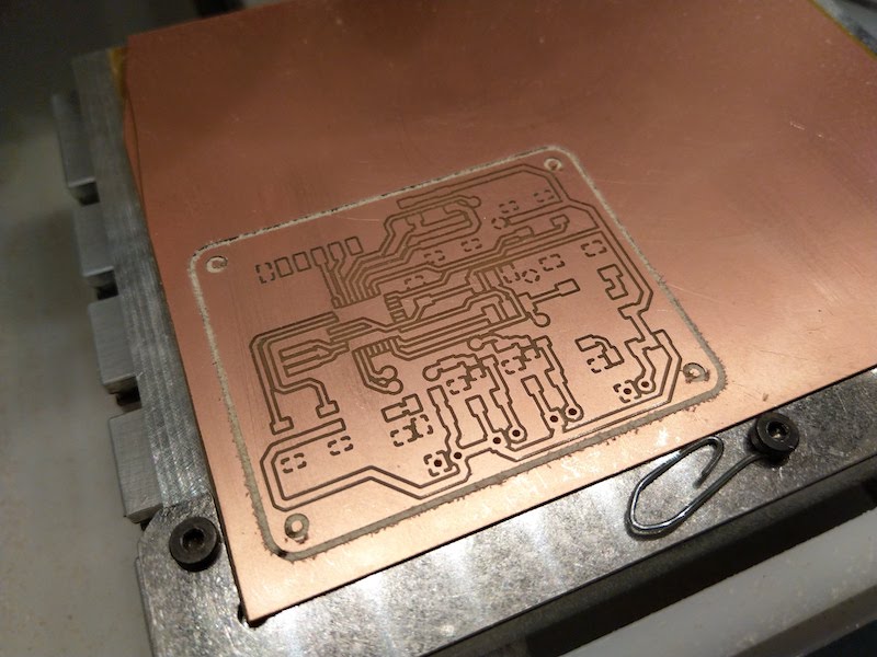
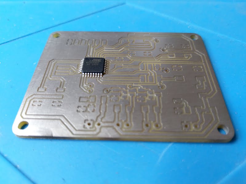
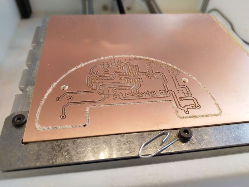
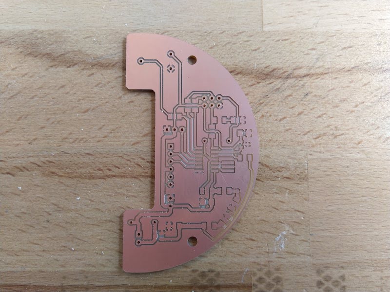
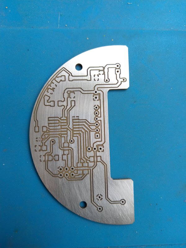
4. Milling the board
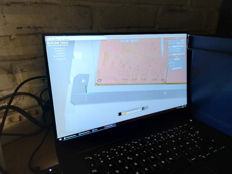
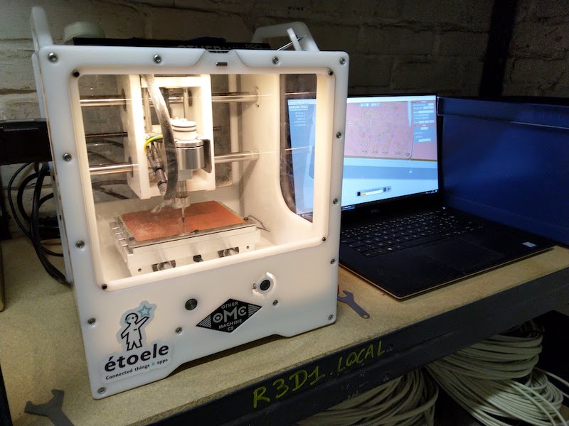
To mill my board, I will use the OtherMill machine and the Bantam software. I opened the file into BanTam to verify that every thinggs are correct and choose the right parameters for the PCB milling I found during week 07.
| The maximum size of my PCB | Creation of the outline | Creating the PCB |
|---|---|---|
 |
 |
 |
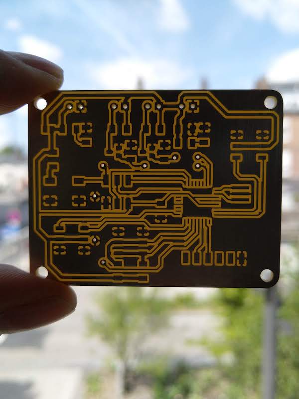
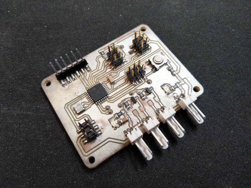
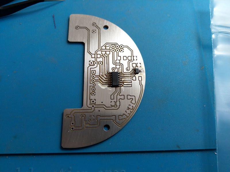
5. Soldering the PCB
Concerning the soldering of the components, I found a great Youtuber named Androkavo that made a lot of videos about how solder CMS packages and others tips. I put a vidéo about CMS soldering. Hope it will help somebody.
| Soldering the 328P | Board finished | Ready to be programmed |
|---|---|---|
 |
 |
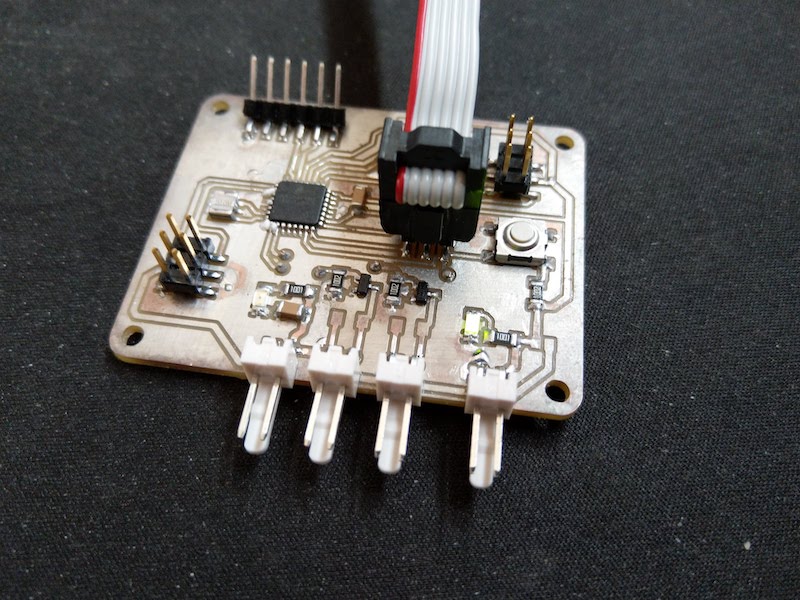 |
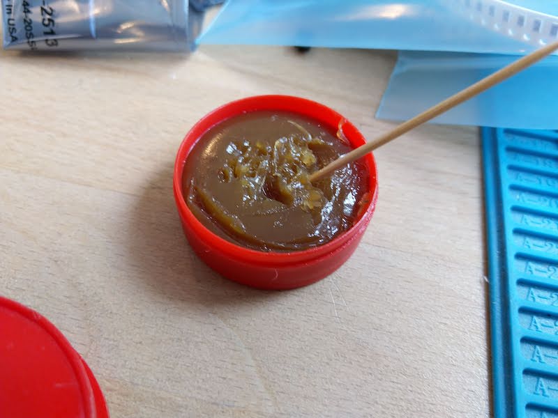
To solder my PCB, I use some flux I bought on Amazon
| The flux | View of the board |
|---|---|
 |
|
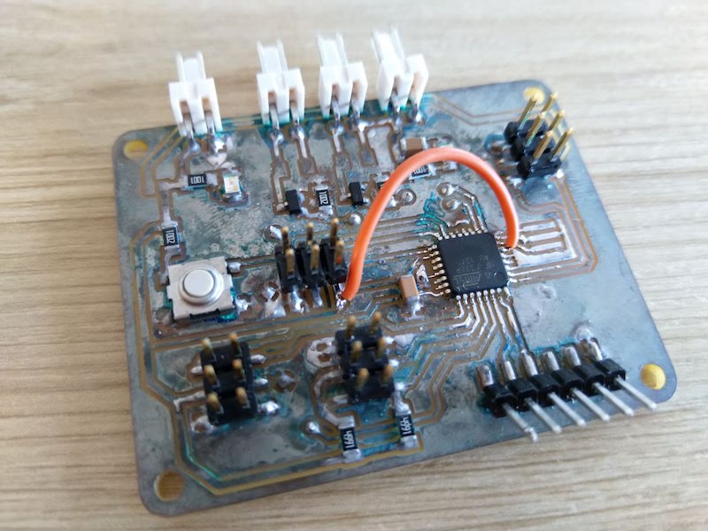
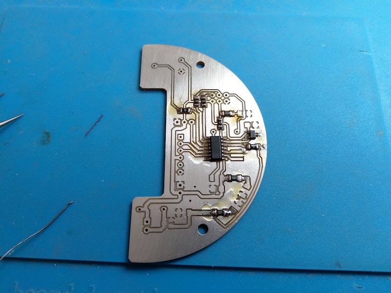
Warning
After one night, the flux I’ve putted on my board and that cleaned with Isopropylic alcohol had completely ruined my board  … Anyway, I try to upload some kind of code into it, but nothing happened. Moreover, some “bubble” appeared under the micro-controller . After trying to clean it, I saw that some traces were completely nibble by the flux …
| My poor board … | |
“Time of death …”“ |
|---|---|---|
 |
 |
 |
So, conclusion : don’t use this kind of flux ! It’s terrible and it make me loose two days of work …
So, at this point, it’s a complete fail. And as I was running out of time, I decided to designed my final project PCB and use it for this week assignment. I will review the 328 board another time because I really think it could be a great board.
6. Create the new Board
6.1 Design of the board
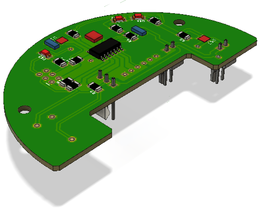
This board will be very similar to the board of week07 but with several improvement :
- I change the pin mapping so :
- The MOSI pin is now linked to a LED (showing the upload and other useful thing like serial communication)
- The Motor pin and led motor have their proper pin
- The button has been moved away
- I add a potentiometer
- The board has a new circle outline so it can fit into my beacon
- The sensor is now on the edge of the board
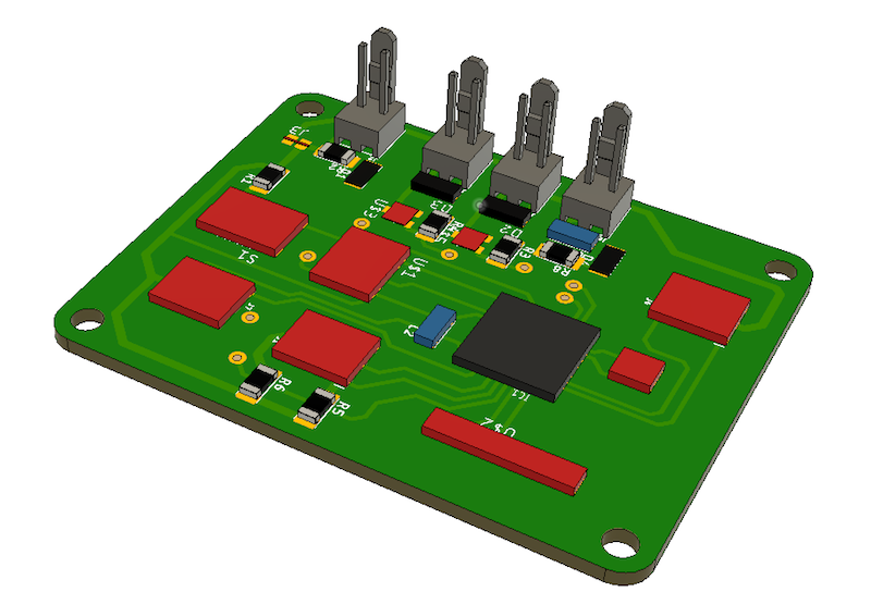
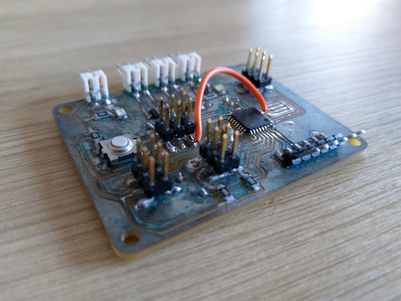
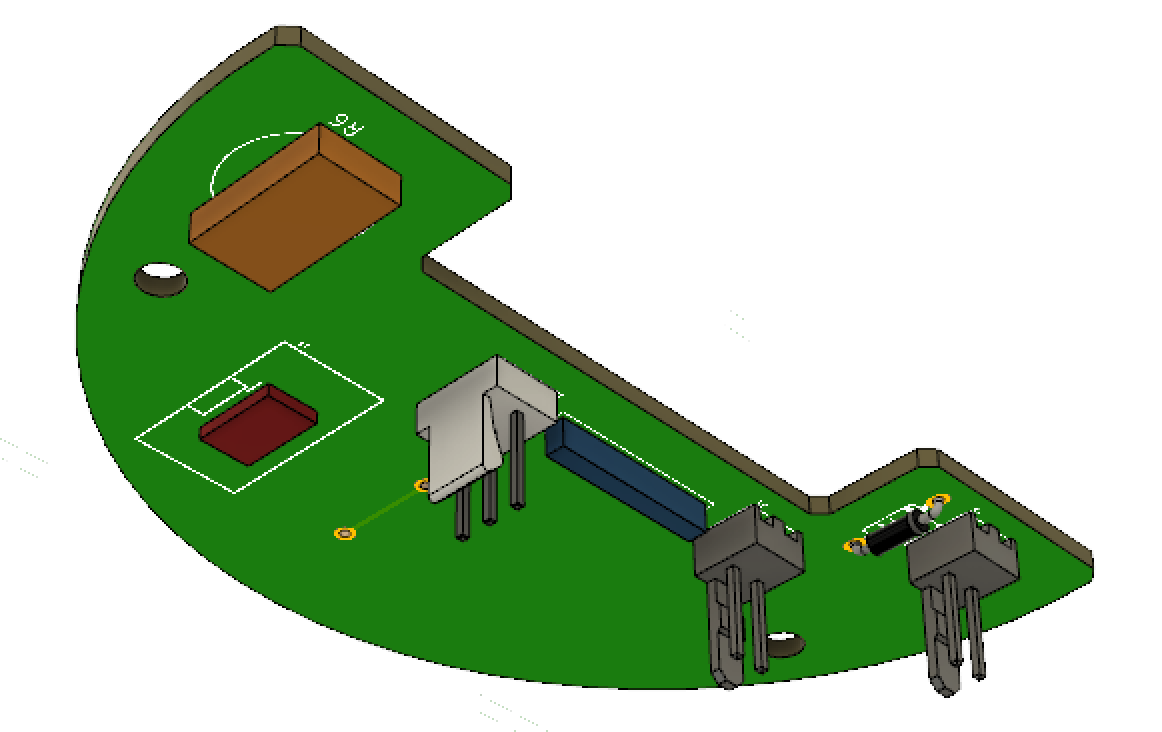
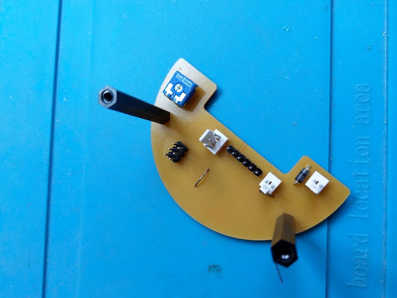
Other improvement, All the CMS and low profile components are on one side, and the connector are on the other side. This will allow me to put the hall sensor just below the mirror support (see my final project).
I will not explain all the process as it is the same as above.
| The schematics | the PCB | 3D view of the low profile components | 3D view of the connectors side |
|---|---|---|---|
 |
 |
 |
 |
The sources can be founded here.
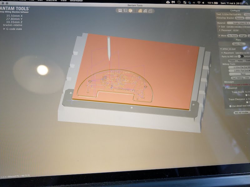
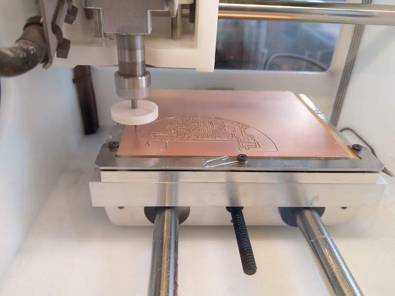
6.2 Milling
For the milling process, I use the same process as above : banTam tool and othermill machine withe to drill bit of 1/32” and 1/64”.
| BanTam tool | Milling | Milling | Results |
|---|---|---|---|
 |
 |
 |
 |
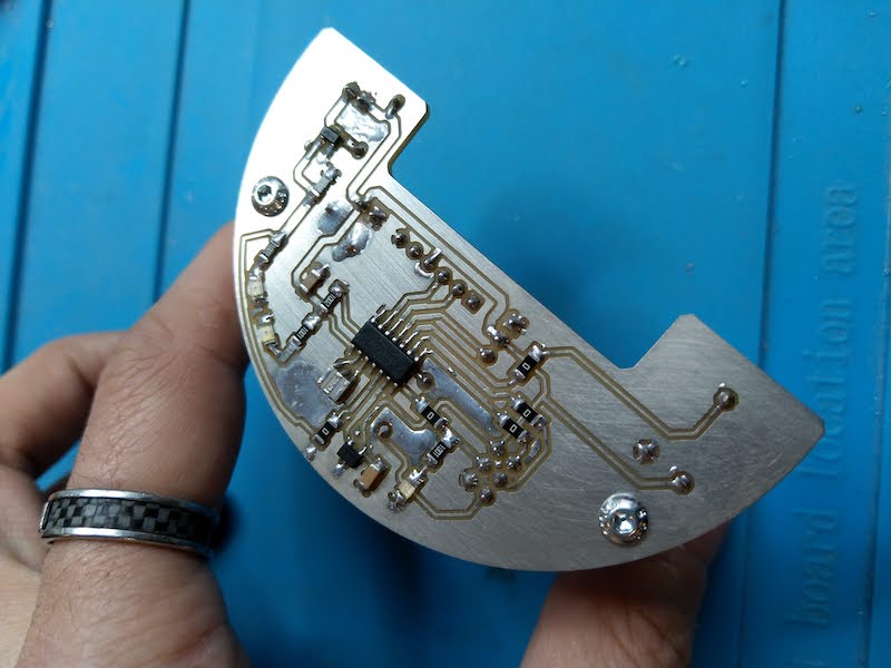
6.3 Soldering
To solder the board, I first cold tin the board and after I use a new flux available at the FabLab.
| The PCB | The flux | Soldering the attiny44 | Soldering the resistors |
|---|---|---|---|
 |
 |
 |
 |
And the results after soldering all the components :
| Top side | bottom side |
|---|---|
 |
 |
7. Programming
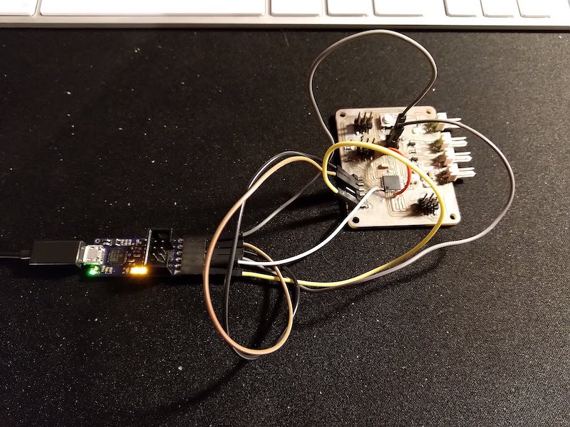
For this assignment, I will use a Uart link between two boards : the one I did in week 07 and the one I did previously for my final project.
The Idea is to, on the sender side :
- Simulate my robot sending speed value to the board in my beacon ( final project )
On the receiver side (final project)
- Update the speed value of the motor into my beacon according to the message received
- Send a simulation of opponent position to my simulation ( see week 16 : Interface and application programming )
Warning
When trying to program my board with the new version of the AVR platform on plateform IO, I got an issue with libusb. To make it work again, I had to re-install libusb :
brew install libusb
and for an unknow reason, also re-install liftdi :
brew install libusb-compat libftdi
For the next parts, I use what I learned during week 16 on the networking. The code are very similar. Please, go to the week 16 assignment if you want more informations.
7.1 Sender
On the sender side I will just send 1 byte to the receiver. this byte will contain the speed value of the motor of the beacon. To do that, I created a function that send 1 byte with a ending charater.
So the buffer send is two bytes long with the message contained into the first byte.
void sendByte(byte message)
{
  digitalWrite(ledPin,HIGH);
    sendBuffer[0]=message;
  sendBuffer[1]='\n';             // Byte that end the communication

  for(int i=0;i<=1;i++)
    {
        Serial.write(sendBuffer[i]);
    }
  digitalWrite(ledPin,LOW);
}
To test it, I will just send an incremented and decremented value into my loop :
void loop()
{
  for(byte i=0;i<=250;i+=10)
  {
    sendByte(i);
    delay(100);
  }
  for(byte i=250;i>=0;i-=10)
  {
    sendByte(i);
    delay(100);
  }
}
The sources are into the gitlab repo : Sources of week14
7.2 Testing Sender
On the video below you can see the results of the data sending to my computer. The board send a byte from 0 to 250 and to 250 to 0 with an incrment / decrement of 10. The raw value you can see are ASCII values prompt by the serial terminal.
7.3 Receiver
On the receiver side, the code is very similar of what I did on week 16 because it send a 6 bytes long message to the computer and receive a 2 bytes long message to update the motor.
The core of the code is the sending function. I need to send the following informations from my board to my application :
- byte - a char to signify the begin of the communication. It will be ‘b’
- unsigned integer - Distance of the robot
- unsigned integer - Angle of the robot
- byte - a char to signify the end of the communication. It will be ‘\n’
As I cannot send int value with my serial communication, I will parse each unsigned integers into two bytes.
To do that I will use the following to parse an integer into two bytes :
byte1=distance >> 8;
byte2=distance & 255;
And then implement it on the ATTtiny sending side :
void sendPosition(int distance,int angle)
{
  digitalWrite(led,HIGH);
  sendBuffer[0]='b';              // Byte that begin the communication
    sendBuffer[1]=distance >> 8;
    sendBuffer[2]=distance & 255;
    sendBuffer[3]=angle >> 8;
    sendBuffer[4]=angle & 255;
  sendBuffer[5]='\n';             // Byte that end the communication

  for(int i=0;i<=5;i++)
    {
        Serial.write(sendBuffer[i]);
    }
  digitalWrite(led,LOW);
}
I also need to receive value from the sender. To do that I created a function that update parameters into the receiver. The idea is that this function can be easily modified in the futur if a need to update multiple paramaters, as long as the parameters are byte and not int.
void updateParameters()
{
  if (Serial.available()>0)
  {
    byte c = Serial.read();
    analogWrite(motor,c);
  }
}
The updateParameters() function will be call the most frequently as we can into the code so we can detect quickly when a message is received.
The sources are into the gitlab repo : Sources of week14
7.2 Testing Receiver
As the receiver part is almost the same as in week 16, I put below the video of the testing during week16 :
8 Testing the complete network
Below you can see the results of the sending value to the beacon board ( the motor led is changing ) and the sending of the value from the beacon board to the computer. So we have a functional network like this :
Sending PCB —motor parameter—> Beacon PCB —positions values—> Computer
Sources files
- Code for receiver part
- Code for sender part
- Board file for PCB
- Bantam file for PCB
- Schema file for PCB