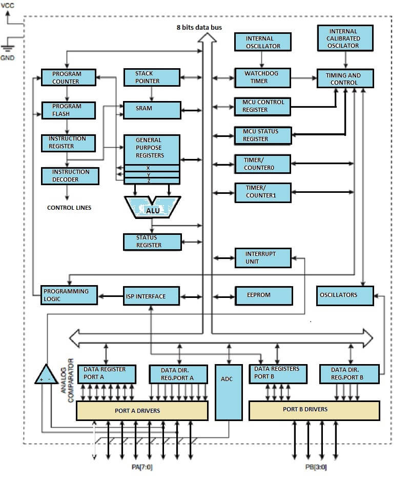
The ATtiny 44A provides the following features: 4K byte of In-System Programmable Flash, 256 bytes EEPROM, 256 bytes SRAM, 12 general purpose I/O lines, 32 general purpose working registers, an 8-bit Timer/Counter with two PWM channels, a 16-bit timer/counter with two PWM channels, Internal and External Interrupts, a 8-channel, 10-bit ADC, Analog comparator, and Interrupt system to continue functioning. ADC Noise Reduction mode minimizes switching noise during ADC conversions by stopping the CPU and all I/O modules except the ADC. In Power-down mode registers keep their contents and all chip functions are disabled until the next interrupt or hardware reset. In standby mode, the crystal/resonator oscillator is running while the rest of the device is sleeping, allowing very fast start-up combined with low power consumption. The device is manufatured using ATmel's high density non-volatile memory technology. The chip ISP Flash allows the Program memory to be re-programmed in-system through an SPI serial interface, by a conventional non-volatile memory programmer or by an on-chip boot code running on the AVR core. You can download the datasheet here.
I have some question, for example ,when I program the fuses, in what stage of the above figure these fuses are programmed?, another questions, whas is the difference between internal oscilator, internal calibrated oscilator and oscilators?, like show the above figure.
I would like to learn more about stack pointer and interrupt unit.
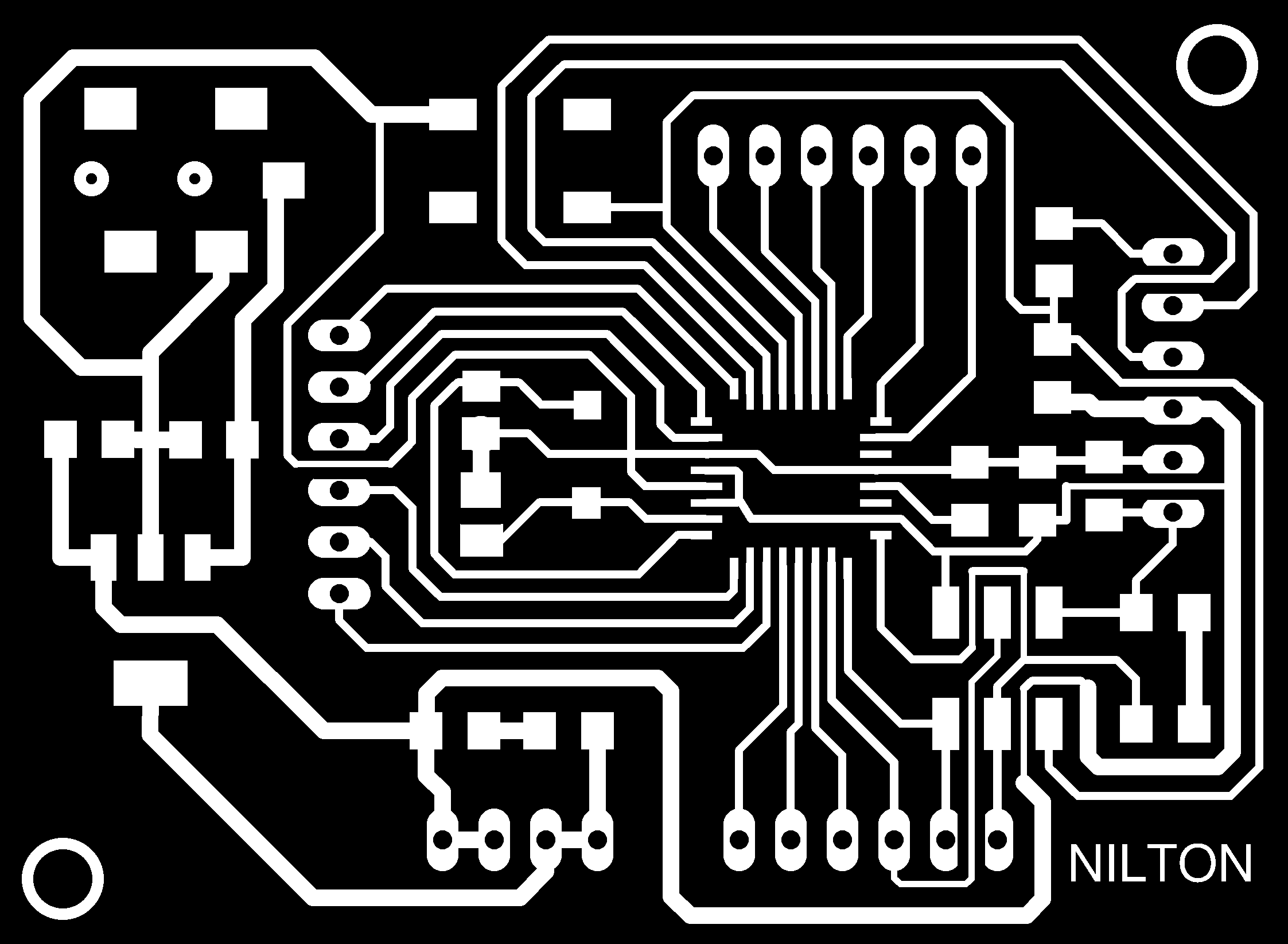
For this assignment I build the fabduino but the circuit was made by Jose de los Rios and Roberto Delgado, I just modified the pcb for my convenience, because I din't have superficial components like a crystal, this was the one.
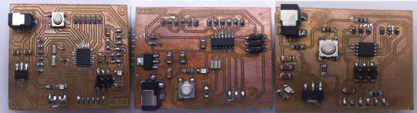
Finally, below i show the fabduino, the attiny 44 and the attiny 45.
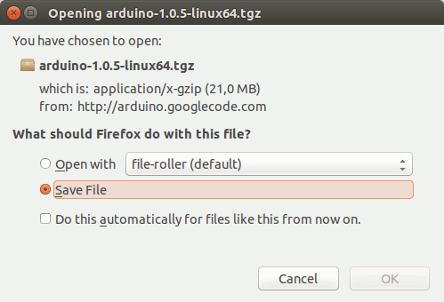
first I install the arduino IDE in linux, surt to the arduino Download page on arduino and download the 64 bit version on the ubuntu version, you might have to update the instructions below. Save the file to your download folder.
Extract the archive and move it to the /opt folder, in a terminal window enter:
            cd ~/Downloads
            tar -zxvf arduino-1.6.4-linux64.tgz
            sudo mv arduino-1.6.4 /opt
Install the required Java Runtime Environment with:
sudo apt-get install openjdk-7-jre
To use the USB port the permissions need to be set to read and write with:
sudo chmod a+rw /dev/ttyACM0
If you use multiple Arduinos, you can use the same method, just raise the number of the port, e.g. /dev/ttyACM1.
Create a shortcut on the desktop:
            cd ~/Desktop
            ln -s /opt/arduino-1.0.5/arduino
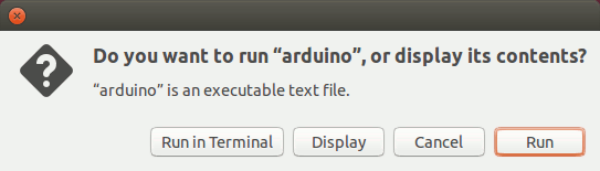
Click 'Run' in the dialog window to start the Arduino IDE.
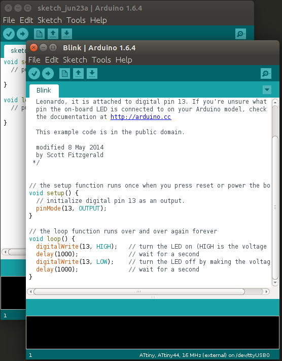
The arduino IDe is now ready for action...! and you can test with the example program called blink.
The figure below show you the same logic to blink a led, but exist difference between 'c program' and 'arduino program', Is common see the arduino program easy, but if you want to learn much more inside the microcontroller I think It's better learn c program, because you have the total control of your microcontroller, but is not so easy to learn this c program.
#include
#include

#define output(directions,pin) (directions |= pin) // set port direction for output
#define set(port,pin) (port |= pin) // set port pin
#define clear(port,pin) (port &= (~pin)) // clear port pin
#define pin_test(pins,pin) (pins & pin) // test for port pin
#define bit_test(byte,bit) (byte & (1 << bit)) // test for bit set
#define led_delay() _delay_ms(100) // LED delay
#define led_delay2() _delay_ms(1000)  // delay 1 s

#define led_port PORTB
#define led_direction DDRB
#define led_pin (1 << PB5)

int delay10s(void){         // function with 10 seconds delay approximately
   for(int i=0;i<10;i++)
  {
    led_delay2();
  }
}

int main(void) {
   //
   // main
   //// the external clock is 16MHz
   // set clock divider to /1
   //// if you want change the clock you can set the parameters below
   CLKPR = (1 << CLKPCE);
   CLKPR = (0 << CLKPS3) | (0 << CLKPS2) | (0 << CLKPS1) | (0 << CLKPS0);
   //
   // initialize LED pin
   //
   clear(led_port, led_pin);
   output(led_direction, led_pin);
   //
   // main loop
   //
   while (1) {
     delay10s();// loop whit 10 seconds delay and two blink of led with 100ms delay
      set(led_port, led_pin);
      led_delay();
      clear(led_port, led_pin);
      led_delay();
      set(led_port, led_pin);
      led_delay();
      clear(led_port, led_pin);
      led_delay();
      }
   }
Now you can see below the video where I show you the fabduino when it is working.
At the same way you can programming the attiny45, You need to change the parameters, like board: attiny, processor: attiny45, clock: 8MHz internal.
At the other way you can programming the processor with the makefile: in the terminal windows enter the command: