Week 6 - Electronics design
1. EQUIPMENT
The equipment used was:
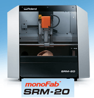
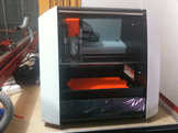
SRM-20 MonoFab Roland
This machine is capable of cutting a wide variety of materials, including chemical wood, acrylic, and ABS. It is also capable of a range of accuracy settings from prototype to product design. In the last assignment i used
The maximun cutting area in the x-y plane is 152.4 mm x 203.2 mm ; and in the z directios is 71mm; for more details you can see the
user's manual SRM-20
2. SOFTWARE
Electronic Design
Eagle is a powerfull software that provides quality PCB design, where you can use a schematic editor, layout editor to make an excelent design.
Eagle is a powerfull software that provides quality PCB design, where you can use a schematic editor, layout editor to make an excelent design. You can download de eagle schematic
HERE
.
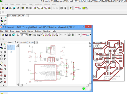
This software help us to export the pads and trajectories in png format, and then it can mill the printed board circuit.

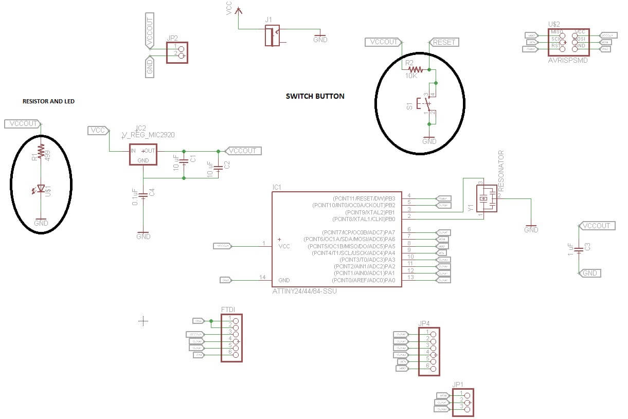
With the help of a tutorial about eagle, I made a new redesign, like I show below, I added a pulse switch, a led with its resistor, the value of resistor is 470 ohm.

At the schematic circuit, I modified it to insert a light emisor diode, resistor and a pulse switch, connecting the pulse sitch to the input pin of the microcontroller and led to the output pin, like I show below.
2. PROCESS
Fabmodules
STEP 1: enter the adress www.fabmodules.org into the search page.
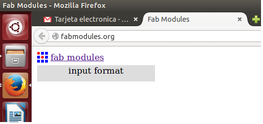
STEP 2: click on the input format, you will see a menu, like i show below.

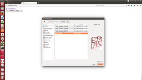
STEP 3: click on the image (.png) format, previously you export the circuit design make in eagle to png format, it will open a windows to search the png file, like i show below.
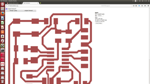
STEP 4: A window will show the circuit to print, like i show below.
STEP 5: click on the input format, you will see a menu, like i show below, where you have to choose the machine conected to your laptop, in my case I chose the Roland Mill (.rml).

STEP 6: Then choose the process, click on the input format, you will see a menu, like i show below, where you have to choose the machine conected to your laptop, in my case I chose the Roland Mill (.rml). Then click on the calculate button, and it show the trajectory of the mill machine to make a printed circuit board.
But when I tryed to work with the SRM-20 with the fabmodule I had troubles and I didn't get to work with the SRM-20.
There are some parameters:
                tool diameter(mm) = 0.4
                overlap(0-1) = 0.5
                intensity(0-1) = 0.5
                number offset= 1
                image threshold (0-1) = 0.5
                dut depth(mm) = 0.1

                Speeds: plunge = 2.0 mm/s
                        feed = 2.0 mm/s

Finally I use the lpkf mill machine and use the software in windows, this was a bad experience. however I made the pcb, like I show below.
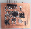
At the end, after learn soldering superficial electronic devices I show below the pcb with the electronics components.
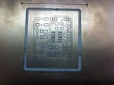
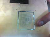
The pcb is shown below, the dimension of this board is 45 mm x 40 mm.
I have any problems to mill the board, one of them was the board was not level and this meant that the router does not do a good machining depth and I did many boards until the routing was perfet.
Another problem was the soldering, because I worked with a tin soldering station, and it's really dificult.