The idea began with the manufacture of the structure of a robot-like wall-e, the realization of the plans were to start difficult because you have to think how to make the structure with the tools we have and with which we made during this course, I divided my project into three parts,
1. mechanical design.
2. electronic design.
3. design software.
Mechanical design
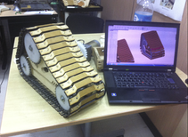
I started my design drawing components Caterpillar wheel in SolidWorks, the mechanical design was difficult, because I had to redesign often caterpillar wheel.
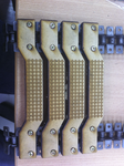
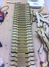
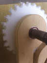
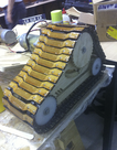
I made several initial tests before getting the final design of the structure, but the biggest problem I had was to make the design of treads that has the robot initially had several ideas for a molding and casting wheel caterpillar, however I wanted a life-size design for the robot is able to charge my son, and I concluded that he should use another way for there to drive the wheel and the robot can move. that is why my design was to use a metal chain connected by cardboard, as shown in Figures below.
You can download the archives from here
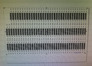
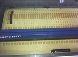
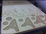
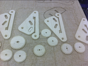
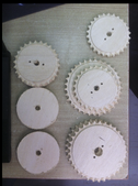
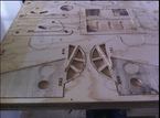
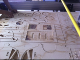
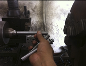
The pieces of the caterpillar wheel was make with the laser cutter epilog, like you see in the figures below.
Cut with laser cutting, parts are assembled with two chains ANSY rolller chain attachment links, like You can see in the McMaster-Carr.
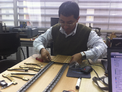
The assembly was the trouble because in my design I did not consider the assembly manually so I had many problems to join the caterpillar wheel. mainly with assembly the dc motors.
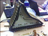
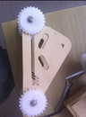
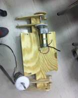
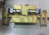
The other design that took me was the support structure of the track wheel, it had to be designed so that the engine is at the top, it also had to have a natural suspension to body weight.
Above I show you the primary design, here I modified because the caterpiller wheel didn't fit, so I had to modified.
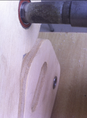
I returned to redesign the support structure caterpillar wheel, further reducing size and increasing some holes for the bearings that support having steel shafts.
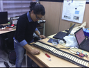
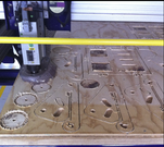
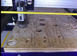
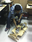
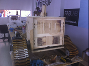
After I designed the structure of the robot body, in this part I had to make a joint task learned in the press-fit, and helped me easily enough for this design.
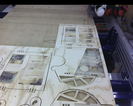
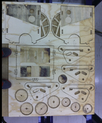
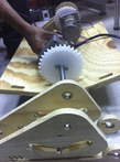
Here you can see all the machining robot, the support of the treads, the body of the robot, the gears to move the chain.
The assembly was difficult because I did not consider the correct dimensions so that the axes of the motors enter easily into the base structure of the wheel track, this part was not easy as it was in the design in SolidWorks.
Electronic design
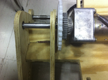
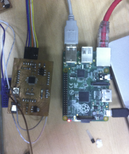
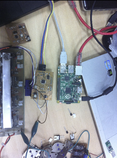
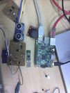
Here I used two DC motor controlled with two H-brigde to control the velocity of the wheel. The problem here was the alignment because the main axis was the two motors, like I show you in the figure.
You can download the archives from here
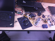
The idea of control was that using raspberry-pi I could remotely manage the raspberry-pi addition to a camera and also control various microcontrollers such as atmega and atiny, the latter through a serial communication and control may have actuators and receive information from the sensors, so was my initial design, and this was varying leaving at the end two atmegas, one for controlling the motors and the other for receiving the signal from the sensors.
Initially I wanted to make a fuzzy logic programming, however due to time I wanted my first robot is functional and you then continue by programming.
Software design
In this stage I made the program in python but into the raspberry pi+, this was only the interface to control a fabduino, I used a remoto control to move the direction of the robot, the fabduino control the motor throw the h bridge, so you can see the movement in the video.
You can download the archives from here
In this part of the software I had several problems because I had a lot of research to control remotely raspberry-pi, I learned some commands in linux aspi ssh 192.168.1.41, this one to take control of the raspberry-pi, but in order to view existed much information on the network, such as putty and others that eventually ended up more confused, however linux had its own remote protocol to see the screen of the raspberry-pi, the nmap command also learned that I needed to know what IP address was my raspberry-pi.