- Home
- My Assignments
- Project Management - Complete
- Computer Aided Design - Complete
- Computer Controlled Cutting - Complete
- Electronics Production - Complete
- 3D Scanning and Printing - Complete
- Electronics Design - Complete
- Embedded Programming - Complete
- Computer-controlled Machining - Complete
- Molding and Casting - Complete
- Input Devices - Complete
- Output Devices - Complete
- Composites - Complete
- Networking and Communications - Complete
- Interface and Application Programming - Complete
- Applications and Implications - Complete
- Mechanical and Machine Design - Complete
- Invention, Intellectual Property, and Income - Complete
- Final Project
Considered one of the funnest weeks of the course, it is
of course the "Make something big" week. We will learn how
to use the magnificent machine known as the shopbot to
produce a spectacular something or rather. This could be a
big piece of furniture or something smaller we have
already made from something like the laser cutting week
blown up to a bigger scale.
Assignment:
MAKE SOMETHING BIG!
25th March 2015 - How big is big?
So the first question that popped into my head over this
assignment was just how big is big, an house?! I settled
on deciding that a nice piece of furniture would suffice
as big after looking at last year's work. But now my next
challenge, what piece of furniture do I make?
In short, two ideas popped into my head. The first one a
hammock designed from a piece of wood using a very large
living hinge design to give it the flexibility. The
second, a kick-ass arm chair with which I can look like an
absolute boss! It turns out the latter will be more
functional, more practical, and easier to make (not to
mention safer!). I refuse to use glue, nails, or screws on this chair, far
too Victorian! Time to do some sketching...
26th March 2015 - My big thing is coming together! (In my head, that is)
As promised, here are my scribblings below of what my
chair will kind of look like:
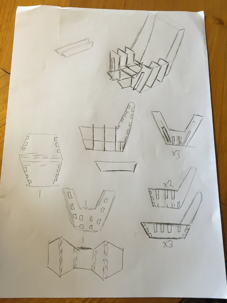
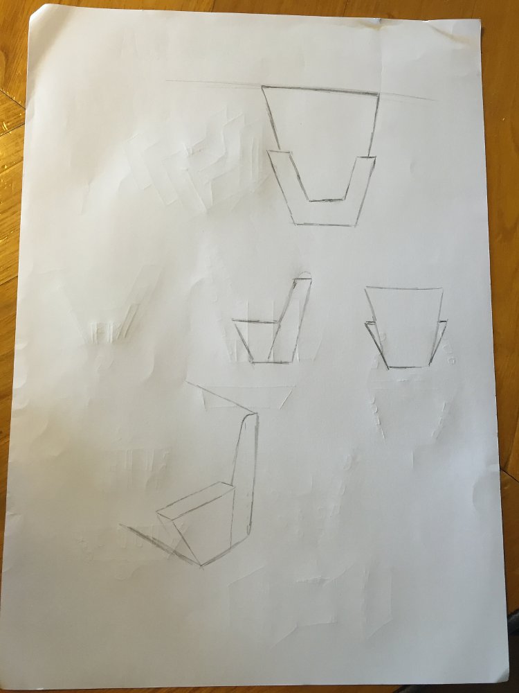
As random and rough as they look they really help me
organise what the design needs to be like in my head
before I start designing on the computer. Also, I
needed to do a fair amount of research regarding
certain measurements of the chair such as seat height,
length, width etc. To translate this to something
useful in Rhino I used a separate layer to create a
guide for where to put the seat, back and so on. I
then used the original layer to draw all the cut lines
of my chair. Becuase it was quite a complex design I
scaled everything down and made a prototype on the
laser cutter with cardboard. Much care is needed when
doing this to ensure all the slots are the right
length ,width and depth.
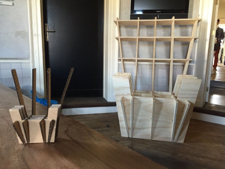
Below is my mini prototype:
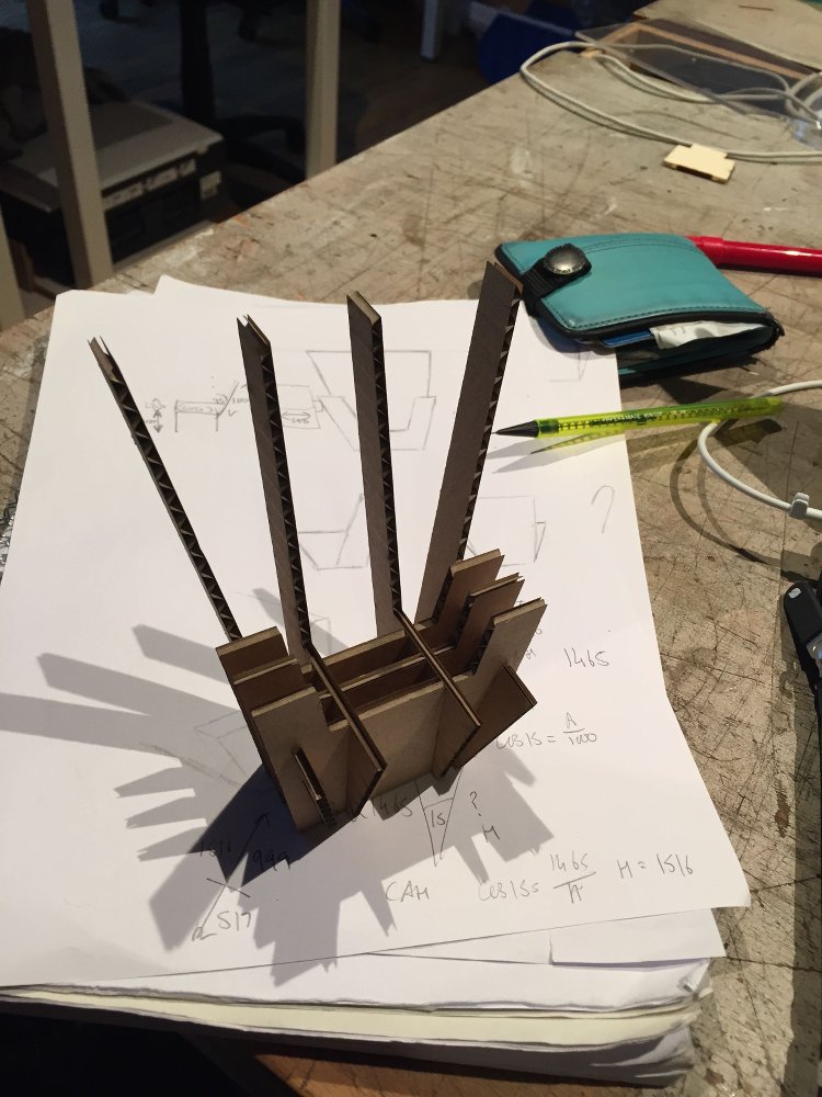
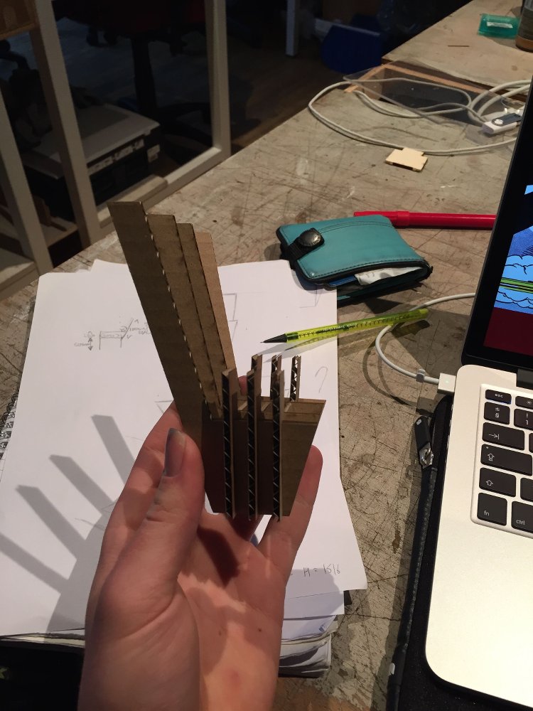
Having this model was really useful, it showed me some
pitfalls which can only be seen by doing this. The
main one is the need for more support for the back,
both vertical and horizontal. Also, it tips back rather
easily so a larger base will help cure that. Apart from that
not a bad frist prototype even if I do say so myself!
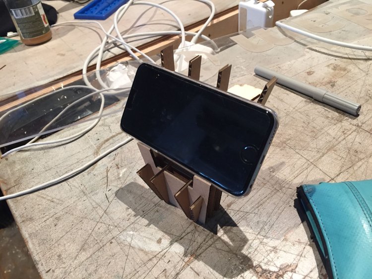
(The prototype also makes an adequate phone stand!
Always useful)
My next objectives are to alter the real life design to
include these changes and cut some test joints to ensure I have
the best fit possible.
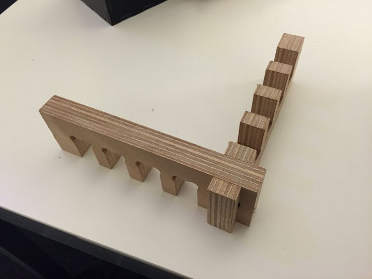
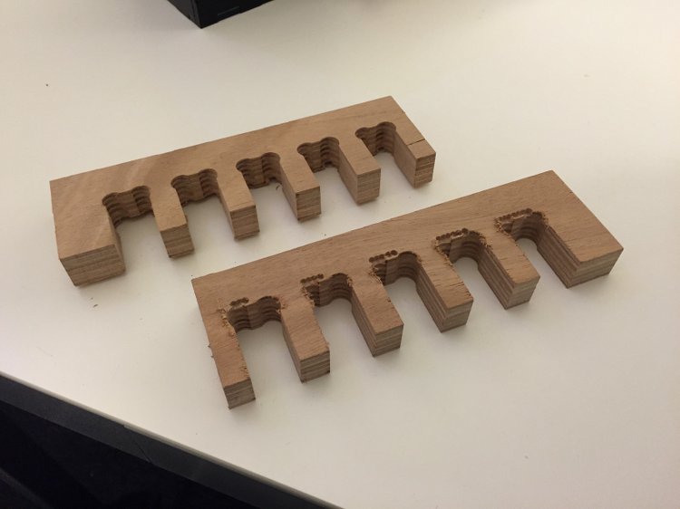
I went on to design some test joints for wood which
was 18.5mm thick (on average). I made two sets of
slots which had slots ranging from 18.3mm to 18.7mm in 0.1mm incraments.
This gave me an opportunity to breifly use the shop
bot which will make things easier later. My design was
pretty simple but I still ran into a few issues:
As good as Rhino is at exporting Illustrator files,
sometimes the software using them can tell it wasn't
made by Illustrator itself. This was the case
for the Part Works software which creates the tool
path for the Shopbot. It refused to open it so I had to
borrow a computer with Illustrator installed on it for
a few moments and re-save an identical file. Then it
opened! Next step was to select the vectors
and tell Pathworks what you want the shopbot to do
with them. I got it to set up a drilling job to make
the markers for my different test joints then a
cutting job to cut out the pieces. I also added tabs
to prevent the pieces from flying off and potentially
causing damage. These are easily added onto the
Partworks software.
I made myself some unessesary work by making my
markers less than 5 mm in diameter. However, it gave me a good
opportuniy to learn how to change the cutting tool mid job.
This is done my using two wreches and twisting
them in opposite directions replacing the tool and
collet and doing it all back up again.
I found that for this 18.5mm thick material that
joints with a thickness of 18.3mm give a tight, sturdy
fit. Now I know this, I can make the final changes to
my design and get cutting!
Click
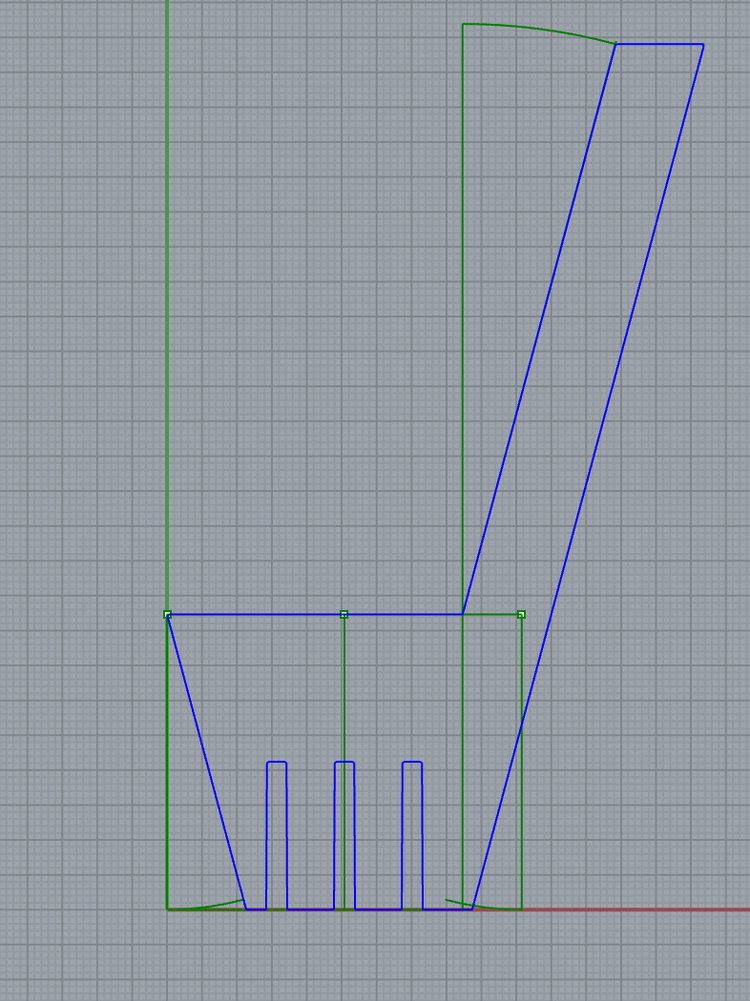
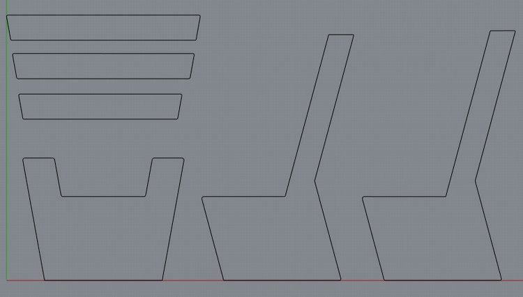
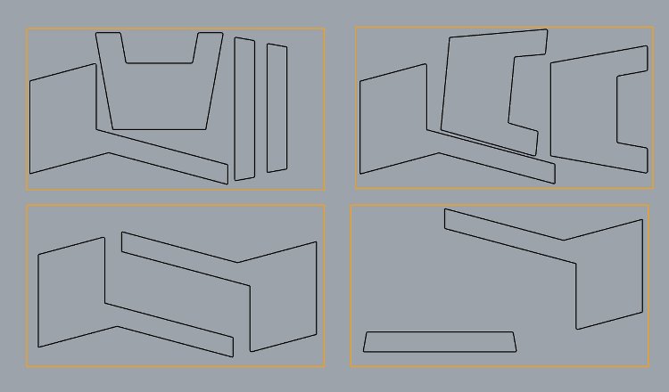
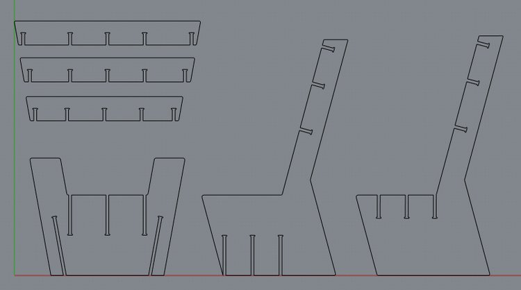
29th March 2015 - Final Designs Complete!
After toiling away at Rhino for some hours and
looking up all the essential measurements needed for
my chair, I have my final design! The frist
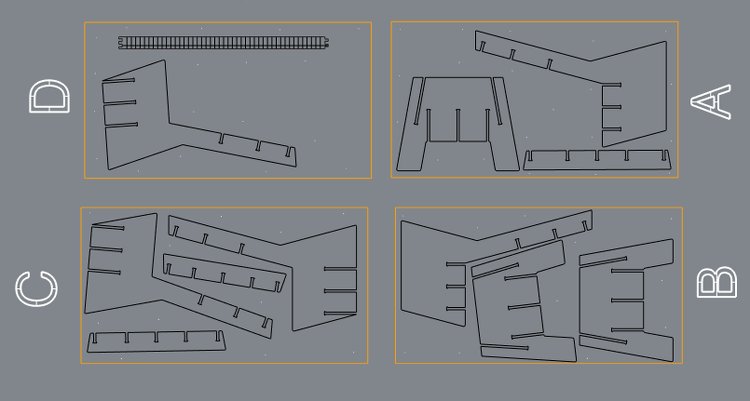
picture shows the individual parts that I deisgned and
the second shows how I have fitted them into 4 separate jobs in the
shopbot bed. The orange rectangles represent the area
of the bed of the machine.
You may think that means I'm ready to process the job
but no! This machine isnt as simple as the Laser
Cutter or Roland Modela. There are more variables to
consider with this machine:
There are a huge range of cutting tools to choose
from. One has to consider the benefits of the
different choices.
It is essential that the user secures their material
sufficiently with screws and be absolutely certain
that the tool won't hit the securing screws during the
job. Depending on the complexity of the job, a
separate drilling job may be required to mark out
where the screws go. A very time consuming process but
also a worth while one.
In addition to the 4 different jobs, I decided to also
do 4 corresponding drilling jobs. I would therefore be
exporting 8 DXF files. To keep them organised I
created 4 folders labelled A, B, C and D. Then in each
folder I would have two DXF files; one called "Drill"
and the other "Cut". That way there would be nearly
zero chance of me screwing up which job to do!
One issue I had was that I wouldn't know the exact
thickness of the material I will be using until
tomorrow morning as I still need to purchase it. That meant I wouldnt be able to add
any joints until I go to the shop in the morning and
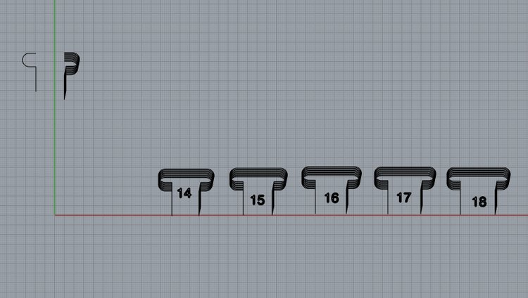
see what is avaliable. To make it easier to design and
add the joints I made a T-bone joint template which
would easily give me a range of 10 joints varying by
0.1mm each. Take a look below:
Time for some sleep followed by an early start as the
wood shop opens at 8:00 AM!
30th March 2015 - Shopbot day!
So today was the much anticipated shopbot day!
This was gonna be a demanding day; both physically
and mentally. First job was to go and find what
wood was avaliable at the shop and then add the
correct T-bone joints to my design. I was going for
as cheap as possible and came across some nice
boards that are used for flooring. They weren't
the best quality but it came in the thickness I
wanted (18mm but was in fact 18.1mm when measured
with vernier calipers). I had learned from my test
joints that I should make the joints 0.2mm smaller
than the thickness of the material to ensure a
good, tight fit. I would rather have a joint a
tad too small than a tad too big!
I hot footed it to the nearest coffee shop and
added T-bone joints of 17.8. Theoretically I
should have added 17.9 but I made the assumption
that some parts of the wood are bound to be 18mm.
Following my "tad too small over tad too
big" philosophy, I went with the 17.8.
So I went back to the shop, purchased the wood and
brought it to the lab with the help of Shirley,
another Fabacademy student.
The next step was to prepare my first file. This
was the drilling job (or "drilling job A"
rather!).I used a 3mm tool and the whole process
took about 20 mins including fitting the screws.
I had a small battle with the program over which
side of the vectors it should cut. This was due to
the program interpreting the vectors as separate lines.
This was fixed by using a function which joins
selected vectors together. I could then create the
tool path on the correct side of the vector. For
the cutting I picked a 5mm tool. It is also essential
to add tabs so that the part doesn't move during
the job.
When the job was complete I unscrewed the
material, gave it a good shake, and all the parts
popped out. Then to save time later I would start
the next job and smooth down the parts from the
previous job during that time.
The first job made an awful lot of noise! To
reduce this in the following jobs we reduced the
cut depth from 3.2mm to 2.5mm. This would add time
to the job as it has to make more passes, but it
also meant that the noise was reduced and there
was less chance of the tool breaking.
To smooth the parts, I filed down the edges and
the tabs followed by a bit of sanding with some
sand paper. Last thing I would want is a splinter
in my backside!
Below is a much needed time lapse of this work
flow. I particularly like this one because you can
see me doing the finishing process while the
machine runs the job.
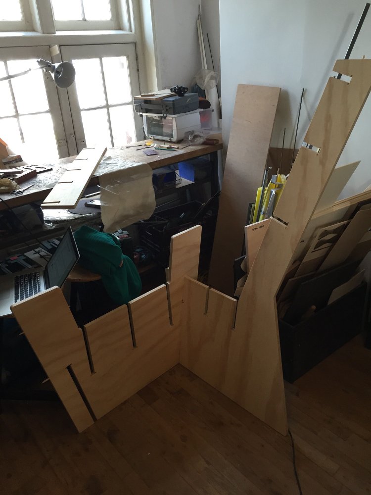
After the first job I was able to put two of the
parts together so that we had an early indication
of the volume of the chair. Got me pretty
excited!:
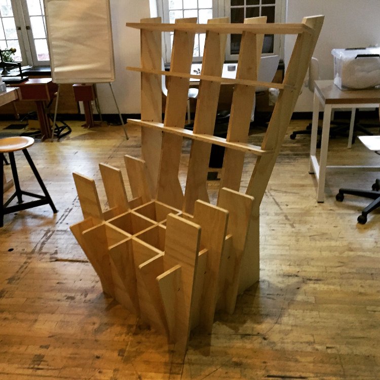
After 3 more jobs for the machine, I had all the
parts. I began assembling it during the other jobs
but now I could finish it off! The joints were
tight... in fact...
very tight! It took a lot of effort to hammer
together (I looked like a psycopath while doing
it!).
Sadly there were two defects/issues with the
prototype. The first one was that one job went off
of the edge of the bed a few millimeters. Also,
the cross sections didn't sit flush with the back
of the chair as they should. Sadly not much can be
done about the first issue for now but I will
return to the lab tomorrow to sort out the second
issue. Apart from that the chair/throne looks
pretty awesome!

Click
31st March 2015 - Fixing the miscalculation!
After a bit of sawing, a bit of filing down and
a second pair of hands the chair was finally
finished. The next step will be making cushions to
fit. Here it is along side its little brother!