In this week of the academy we looked at the diverse range
of methods to 3D print and scan objects. Neil told us how 3D
printing in the lab is the equivalent of using a microwave
in the kitchen. 80% of the time another machine will do a
better job; but 20% of the time the 3D printer is the ideal
choice. The reason for this is because it can produce
objects that could not be made subtractively (this is where
the machine removes material to make an object, like the
laser cutter does). The 3D printer produces objects
additively, as in making up the object from scratch by
adding the material. This enables various useful objects to
be produced in one job. Classic examples are enclosed ball
bearings and bike chains.
This week's assignments:
Design and print a 3D object
Scan a real object to turn it into a 3D image
Aims for this
week:
Put more effort into time management!! (started to slack
last week... finished the assignment with time to spare but
didn't try to work ahead with final project)
25th February 2015 - Oh what to 3D print... Ah HA!!
So as soon as we were given the assignment to 3D print an
object I thought why not make a bike light housing and all
the electronics to go with it. So tonight I am going to
design it and hopefully get it printed tomorrow. This is a
good opportunity to prototype a potential part of my final
project as well as really test my design skills in terms of
ability and lack of time.
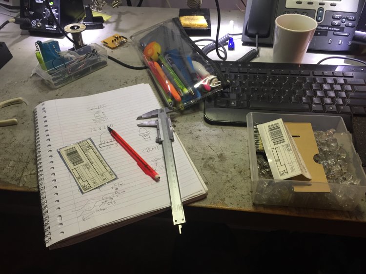
As I will be stuffing my printed object full of
electronics, it was essential that I take measurements of a
few components that I would be using. So I took out a pair
of vernier calipers and set to work! I took measurements of
a 10mm LED, a 9V battery clip and a magnet (could be an
interesting way to secure the light!)
I will chug away at rhino and show you guys my
progress tomorrow. This is my first change to do some 3D
modelling in rhino so it's going to be a big learning curve!
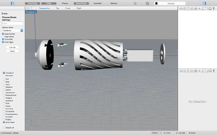
26th February - Modelling complete
After a very late night modelling and not enough
sleep, I came up with this design:
So first we have the clip which will hopefully fit to most bike handle bars
on the left.
Further along we can see these swooping lines cut into
the body of the light. In real life this wouldn't be
the most practical as the electronics would be more
open to the elements. You're probably thinking why
would I put holes the the body?! Well, this is one of
the things that means the design cannot be made subtractively, which was one
of the requirements for this week's assignment of designing and
printing a 3D object. The rest of the design features
also make this impossible to be made subtractively.
The circular disc hanging out at an angle is a flap
connected by a living hinge. The holes in this disc
will house 3 10mm LEDs. Inside the body there is a box
shape which will house a 9V battery and below that
there is a small indentation for a magnet. The idea is that the small magnet will assist in keeping
the light secure on the bike.
After presenting the design to the gurus at the lab I
was met with disappointment
as the type of 3D printers
they have in Fablab Amsterdam are unable to deal with
areas which overhang by more than around 45 degrees.
This is because there is nofacility
to support these overhangs sufficiently. It could be done by printing
supports to go with the overhang but this would then
need a lot of work to tidy up afterwards.
What I then did was develop a second version of my
design. I sliced up the object and turned it into a
press fit construction kit. In all honesty, this was a
real pain to try and do. Rhinoceros started to behave
weirdly when trying to merge two objects after being
sliced. Random objects would disappear! Eventually I
managed to make a mesh of the parts that were playing
up. It still isn't perfect so I will try to make some
improvements in time for 3D printing.
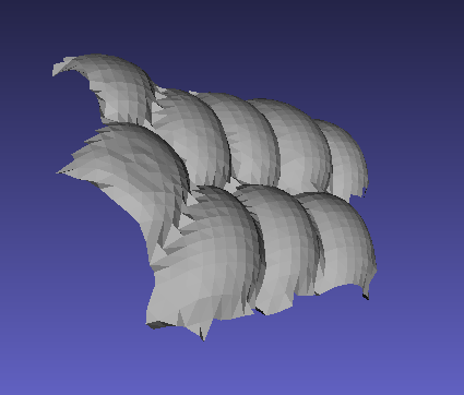
The other half of our assignment is to scan an object
so it can be viewed on the computer. Organic objects
are the best thing to scan as they are the hardest
things to draw on CAD programs. I chose to scan some
sweetcorn on the cob. It has a nicely detailed and
complex texture which would be great to scan. I
started with a phone app called 123D catch. The app
cleverly uses the phone's accelerometer to judge the
relative positions of the photos you take of the
object and stitch them together. Take a look at the
outcome below. Considering its made from just a few
pictures taken on a phone, it's pretty good!
There are of course much more accurate and tidy ways
of 3D modelling which won't leave the mess that the
app tends to leave. Another method is to use the
Roland Modela that I used to mill out the circuit
board. Except with a different tool which is used to
measure the parameters of an object secured on the
milling bed. Unfortunately I had to leave it to run
overnight and won't see the result until tomorrow (OH the
trauma!). In the
meantime I am going to work on my bike light design
and try to tidy up the press fit version. However, one
last note on 3D scanning the sweet corn. I figured it
could be possible to use part of the scan as a design
for the bike light housing. Imagine, a corn on the cob
bike light.. how random but interesting!
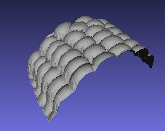
27th February 2015 - 3D scan complete!
So this morning I returned to the scanning machine to see
how well it recreated the shape of the corn on the cob. It
turned out pretty good! But it was going to need some
trimming
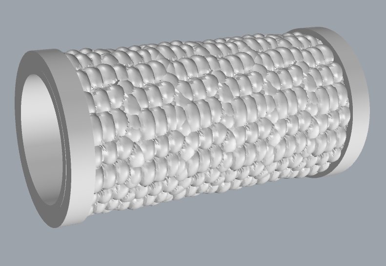
I trimmed the scan so that I had one piece which I could
use to jigsaw many copies of around a cylinder. I used
Meshlab to tidy and trim the scan, then I saved it as an
stl file and imported it into Rhino to piece together.
This process was relatively quick, after less than an hour
at the computer I had a design ready for printing.
I then uploaded it onto the computer used for the 3D
printer and began setting it up. There are quite a few
settings to consider when 3D printing which all make a
huge difference to the quality of your 3D print.
Layer height - A 3D printer has to cut up your design into
lots of layers which it then prints out one by one to
built up your design. This setting determines the
thickness of those layers. It can range from as little as
0.06mm right up to 0.25mm. The thinner the layer, the
smoother the finish (but also more time!!). Because it
wasn't essential that these experimental designs of mine
were printed to the best quality possible, and to save
precious time, I opted for 0.25mm.
Shell thickness - This determines the thickness of the
walls of your design. The 3D printer doesn't print out
shapes as a solid block of plastic, instead, a shell is
made of the design which is filled with a mesh design.
This saves material and time with negligible sacrifice to
strength. Mine have been set to 0.8mm.
Fill density - This determines the density of the mesh
that fills the shell. I set mine to 20%. This is adequate
in normal situations but if the design has to withstand
significant force, values of up to 80% would be more
appropriate. This would have a big influence on job time.
Travel speed - This is the speed at which the nozzle
travels around the printer bed. I set it to 150 mm/s. This
can be further altered once sent to the 3D printer so that
the speed changes for different parts of the design. For
example, outer and inner shells want a speed set to 90% of
that value. That gives a better surface finish. It also
means you have room to make the filler inside the shell
print even faster. This can be set to 120%.
Once the job is sent to the printer a separate window
pops up showing the temperature of the filament, manual
controls and speed controls. The ideal temperature for
most filaments for this machine is 230 degrees celsius. Normally
the user of a 3D printer such as the one we use will want
to change the filament that is currently in ot. So when the user
wants to use their filament, they will need to flush out the old
filament by running their chosen filament until it is only
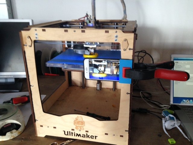
printing with the desired filament. To film this weeks
time lapse video I used a clamp to attach my phone to the
3D printer.
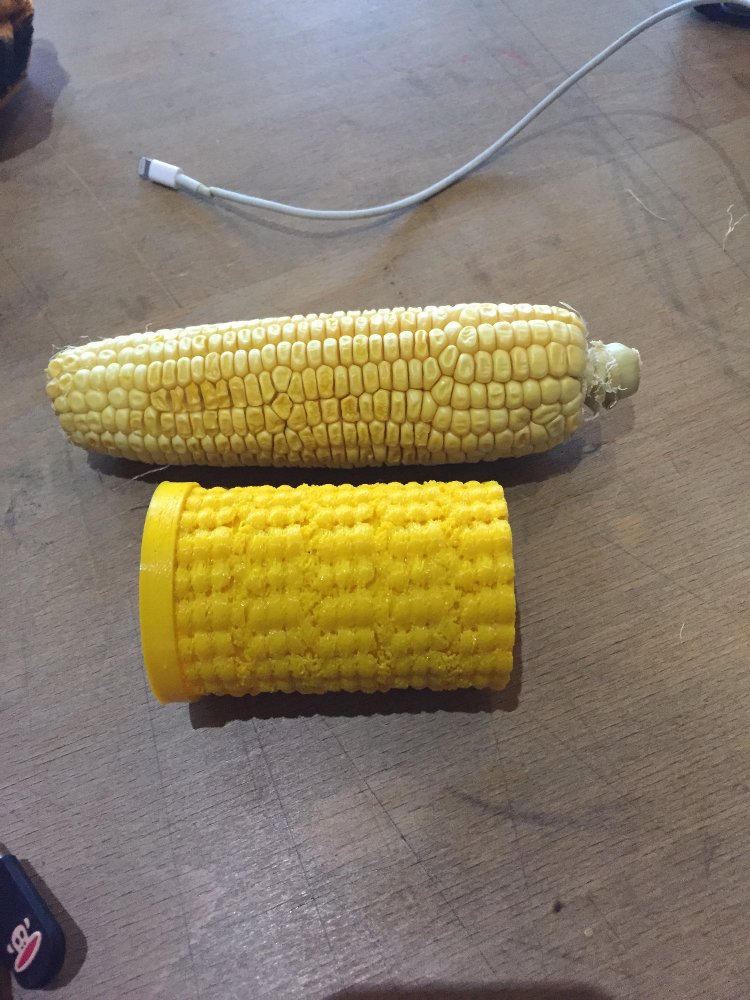
First I printed my digital corn on the cob, it took a
whopping 4 hours to print! I even stopped the printing an
hour early. That was partly to save time but also so I had
a neat cross-section of the print so you can see how the
machine structures it. It isn't a perfect print but you can at least see the individual corn pieces. I will need to do a redesign and reduce the layer height next time.
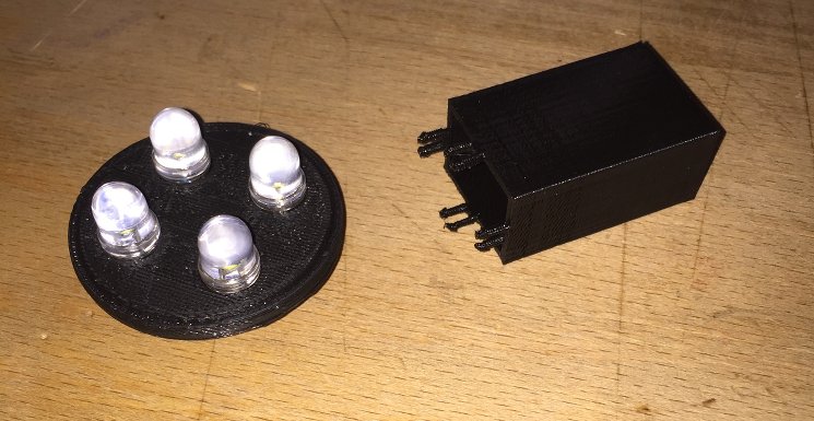
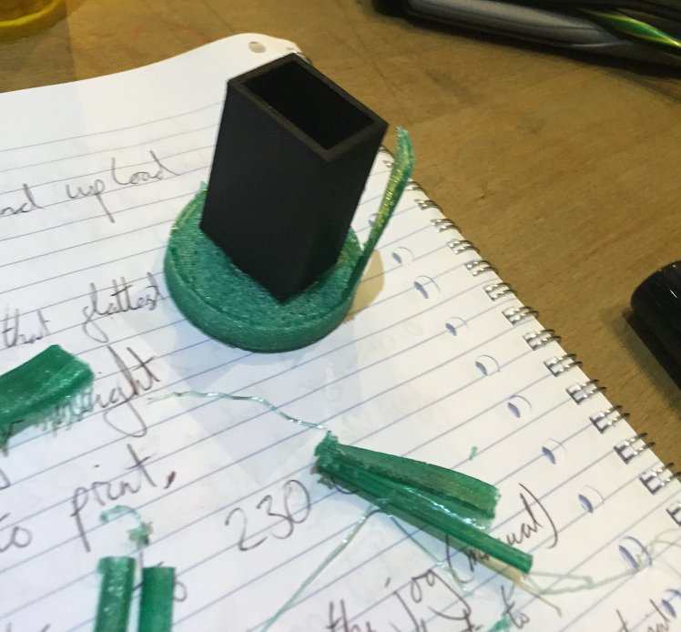
I then set off to print the parts of my bike light
design. I developed a third version which has no clip but
just a magnet housing so that it could still stick to
metal surfaces. I started with the smaller parts, the LED
and battery housing and as time was limited. These turned
out pretty well, the LEDs fitted nicely and the battery
fitted nicely but I still needed to test the push-fit
parts of the design. Also, check out the printing process
on my latest and greatest time-lapse video yet!
After seeing these printed I understood why people find
the 3D printer rather overrated as a method of prototyping
let alone a method of production. The surface finish on
all of these parts were really bad and to improve it would
add even more printing time. But still I pressed on with
printing my own bike light and went to print the bigger
piece. I learned a valuable lesson from this to not make
walls which are too thin otherwise they rip off! You can
see the carnage created below. But you can also see that
my press fit design worked a treat! (Well.... the battery
housing at least)
That concludes my antics for today but I will work on my
bike light design over the weekend and try to optimise it
further.
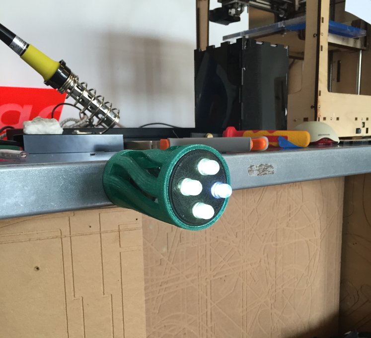
2nd March - Second round of printing my
light
Over the weekend I redesigned the body of the light
so that the walls were 5mm instead of a measly and
ambitious 2mm. I then sent it to the 3D printer and
hoped for the best. Below you can see a time-lapse of the printer
doing it's thing.
I am delighted to
say that not only was the printing a success, but
also the rest of the light! The push-fit LED housing
fitted perfectly,the magnet housing was just right,
and there was no need for the battery housing as the
magnet held it nice and steady. Take a look at it
below!!
That concludes my assignment of designing and printing an object
which cannot be produced subtractively. I am very
happy with the outcome as I have managed to produce
a functional item. It does need some development
like all prototypes but it could be very useful when
developing my final project. With a few improvements
I could prototype my initial idea of making a bike
light, not just a light.
Last night I was checking out how strong the magnet in
my light was. It was so strong it ruined the hard drive
in my laptop! I put the light down on the laptop where
the hard drive is housed without thinking twice about it
until it was too late. I was left without a laptop and
all my write up from the previous day lost. So instead
of trying to develop my digital sweetcorn, I spend most
of the day repairing my laptop. Thankfully I did a back
up over the weekend so I hardly lost any work. Please
learn from my mistake!! Here is me operating on my
beloved laptop below.
After this fiasco was resolved, there wasn't enough
time to run a 3D print job so instead I worked towards
my final project somewhat my dismantling a hub dynamo.
This would give me the chance to note and document the
mastery behind it. This with my understanding of the
principle behind electromagnetic induction will help me
figure out a way of maybe incorporating it in the final
project. I will document all the main features of the
dynamo from inside-out.
Right inside the item we have a coil wrapped around a
plastic collar/roll object. Slits in the walls of the
collar enable the ends of the coil to stick out
perpendicular to the rest of the coil. A similar collar
could be either 3D printed or even made from the laser
cutter using a press fit design.
There is then a very elegant laminate core which is
designed to sit in between the magnets and the coil to
improve efficiency. It is also important to to note that
fact that the layers of laminate lie perpendicular to
the layers of coil. A similar feature could be produced
in the lab.
An axle sits in the center of this coil. One end of the
coil is soldered to a washer which enables the axle
itself to become one of the terminals of the dynamo. The
other terminal is at the other end of the coil which sits
nicely in a slot in the axle so that it can be housed up
the length of it while sitting flush with the axle
surface.
The inside of the hub casing is lined with magnets.
When the coil and axle are placed inside and rotated, a
current is generated.
You can see photos relating to each point below:
My next step could be to calculate the number of coils
used to get an idea of how many I will need and see if
there is a way to manipulate the positions of the
elements into a more convenient arrangement that would
be easy to instal on any bike.