Project Development

This page documents my activities regarding my final project.


19th May 2015 - Finalising my project

In preparation for this final project I have added a project proposal and a project diary to help me document it. I have written a proposal for my project but there are still a few questions that need answering. However, it is still good to have someting to show to our insructors so they can advise us appropriately. You can take a look at the proposal here.

You may notice it's rather different to my orginal proposal but it is necesary that the project is acheivable. Hence why I have simplified the project.

Something I need to work out soon is where to house the hardware. It would be great if I could fit it in a handle bar, but that is a tall order. It will be necesary to think of an alternative if I find it is too difficult to do. One of the things holding me back from doing it is the size of the breakout boards I wish to use. It seems I would have to transfer the components from them onto a board of my own design. This could prove to be very difficult and lead to more debugginh hours (of which there are likely to be many!). In that case, I will house the hardware differently, perhaps an elegant bike light. The downside of this of this is that it makes the hardware far less discrete if it is attatched to th outside of the bike, and more vunerable to tampering.

Today I will try and mill out a fabino board so I can prototype the circuit and get some code made.

**A FEW HOURS LATER**

I attempted to make the fabino board with little success so far as there are various issues with burning the bootloader. So that I can push on with the project, I will prototype the board with an arduino uno. This will let me write the code then transfer it once I get my fabino to work.

Time for some thinking...


A rethink!

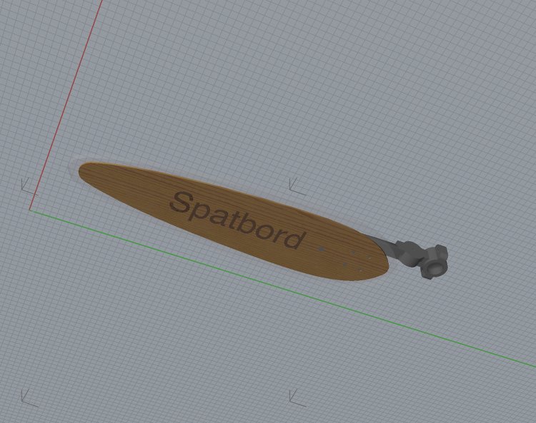
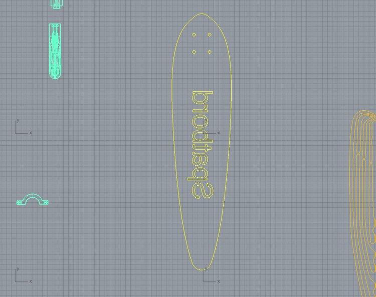
Over the weekend I had a small apiphany and throught to re-assess my goals regarding the project and to change the project but not the heart of it. The heart of it being to benefit cyclists. I have designed a mudguard/fender which incorporates all of the skills taught by the academy:


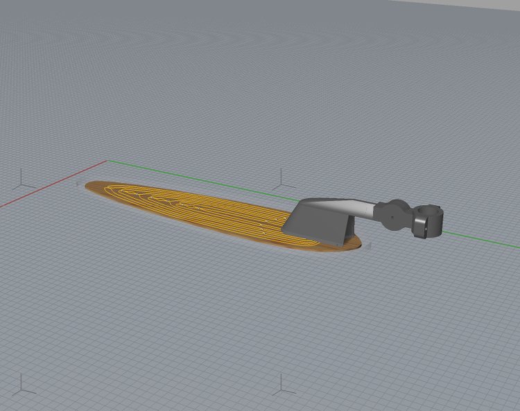
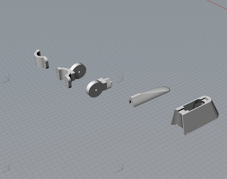
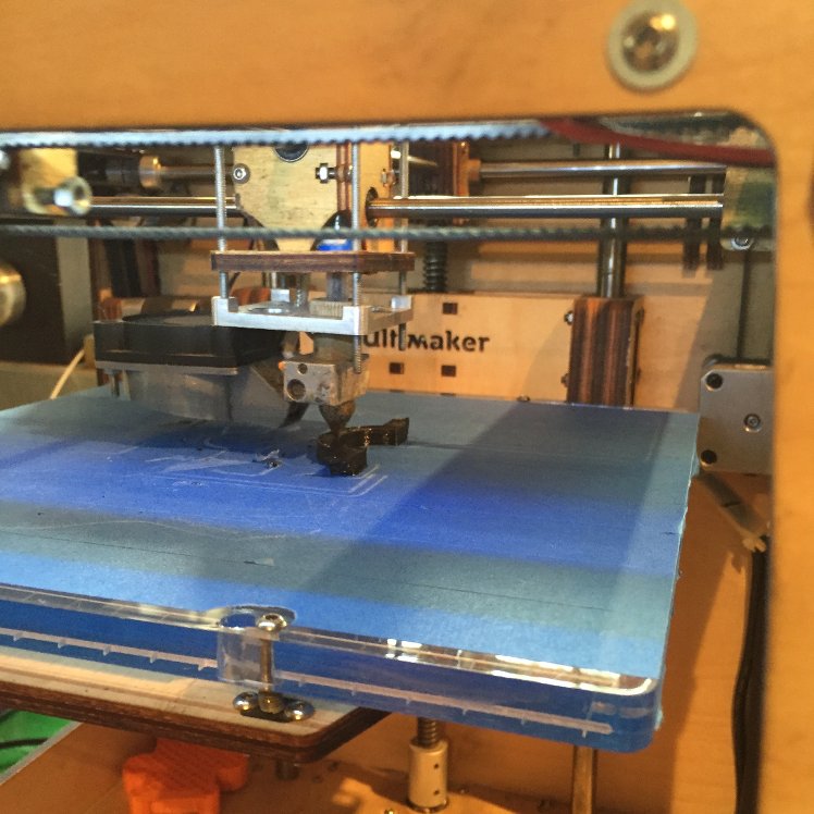
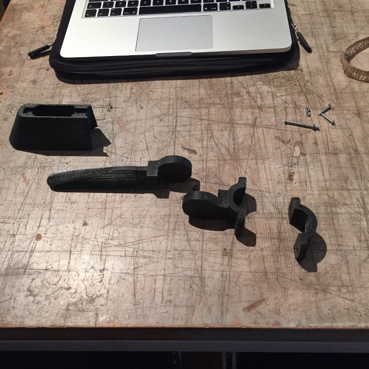
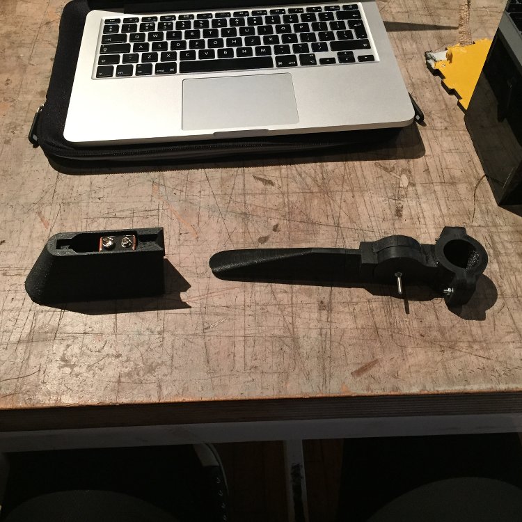
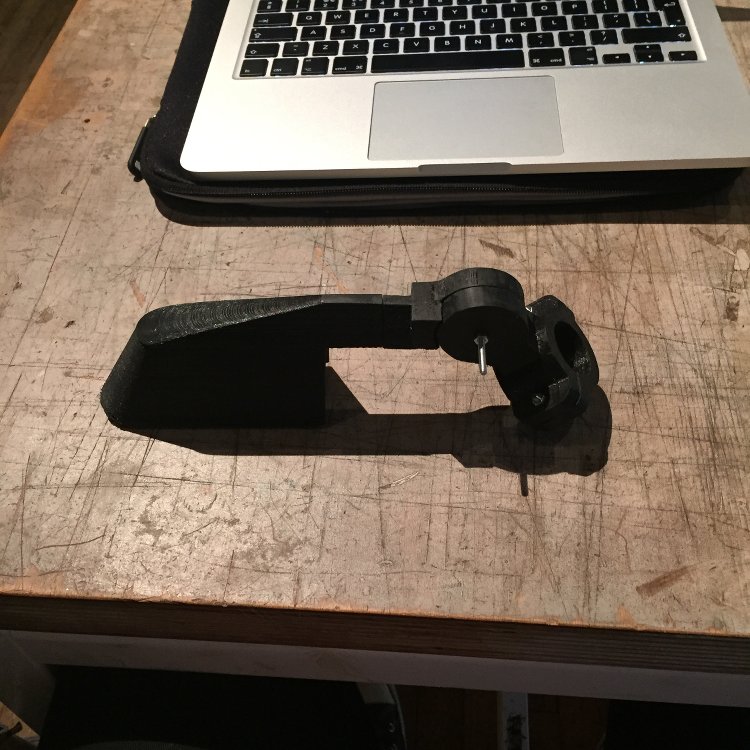
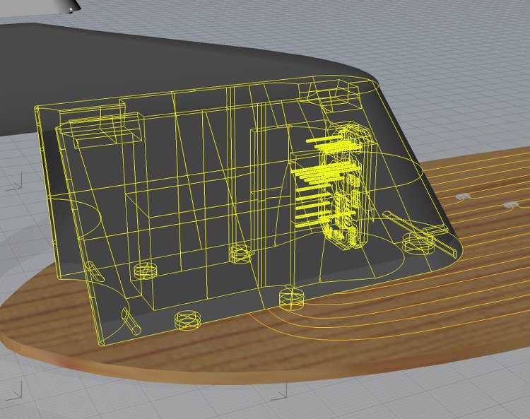
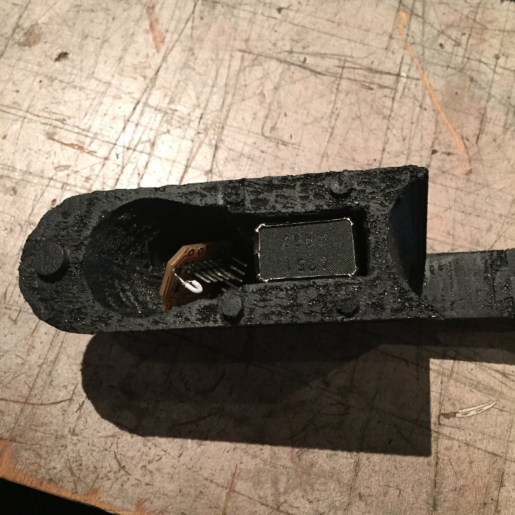
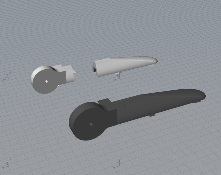
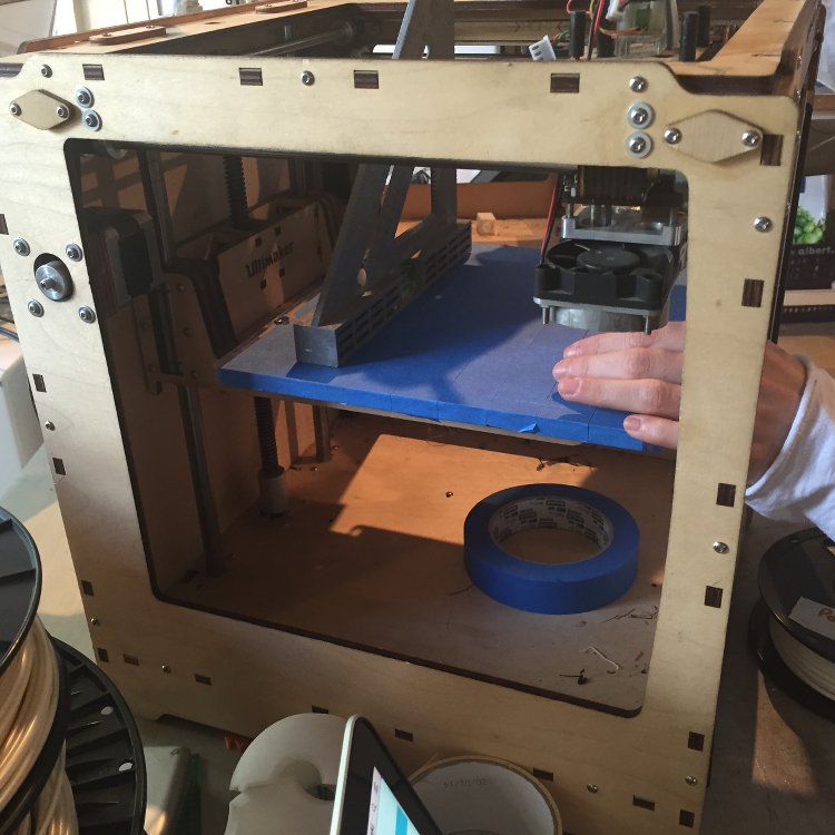
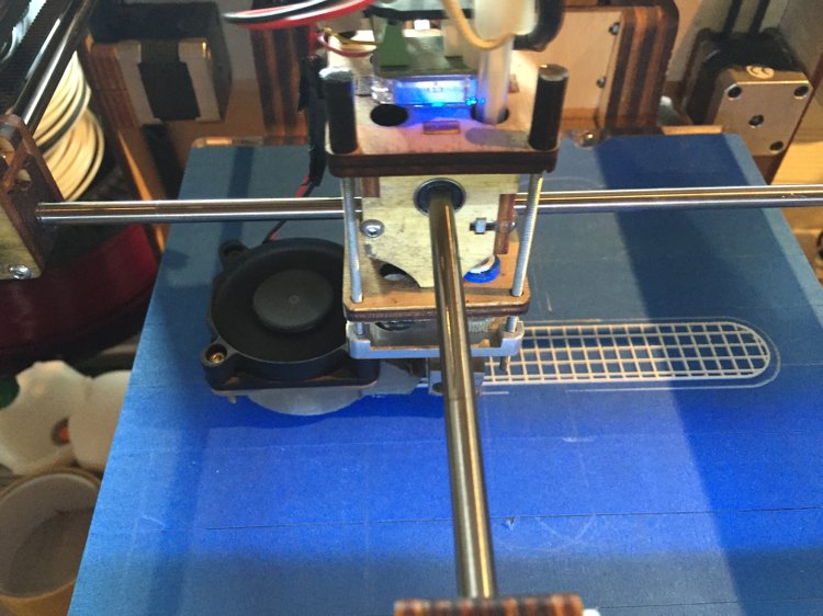
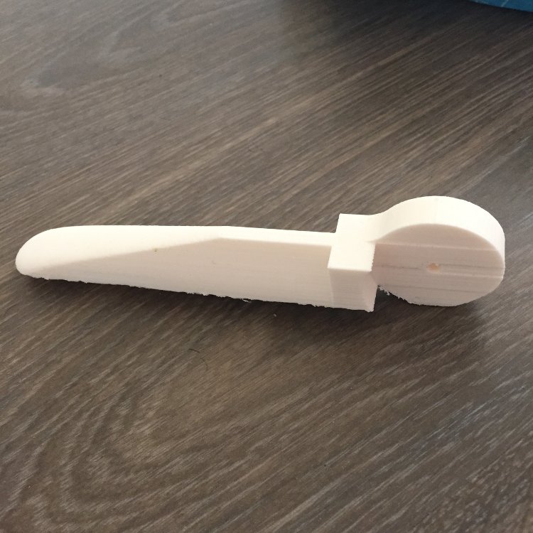
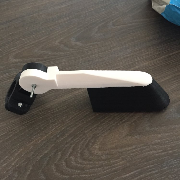
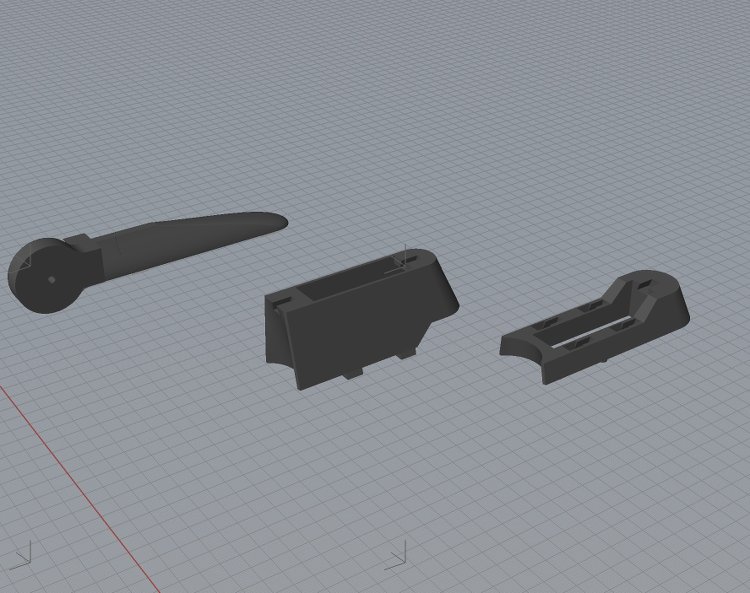
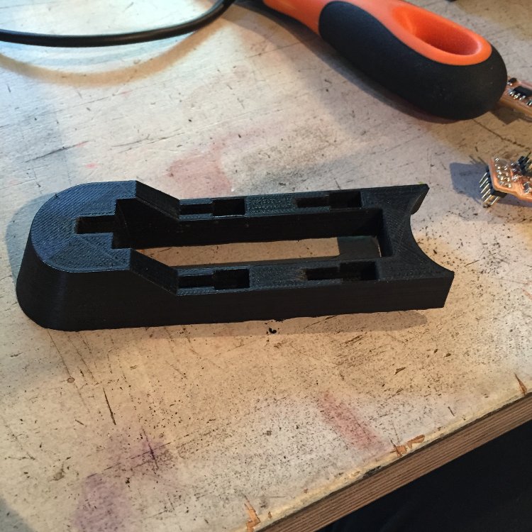
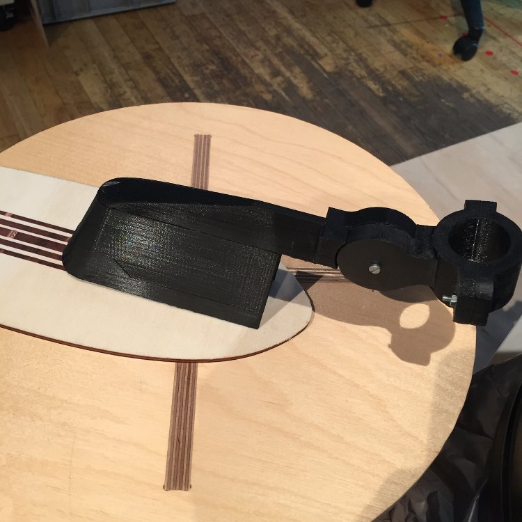
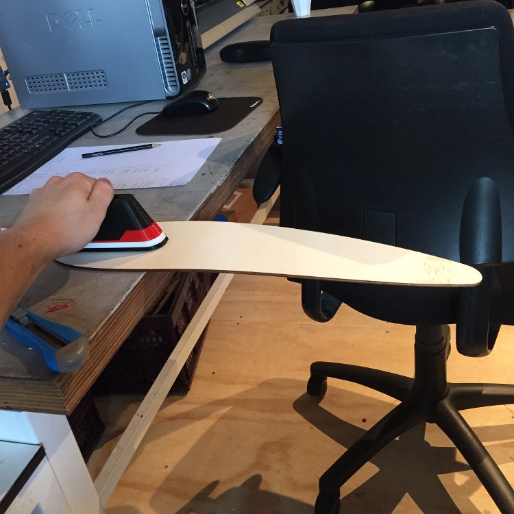
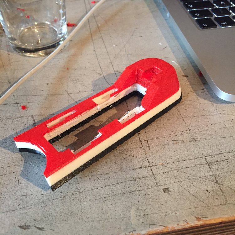
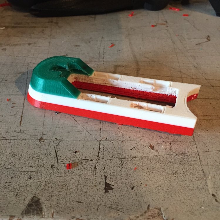
The mechanism to secure it to the bike will be 3D printed. It would be an opportunity for molding and casting but on this occasion I think it will be quicker and easier not to.


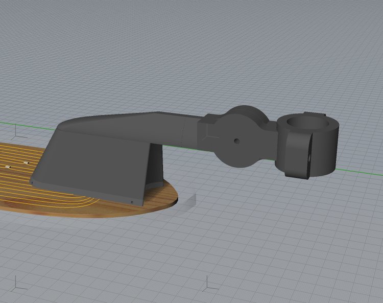
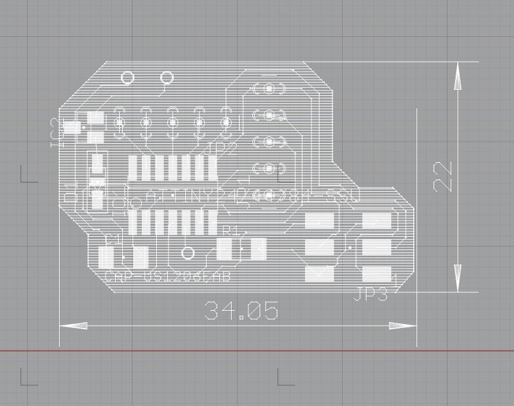
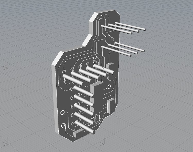
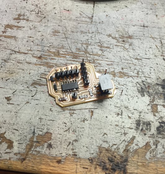
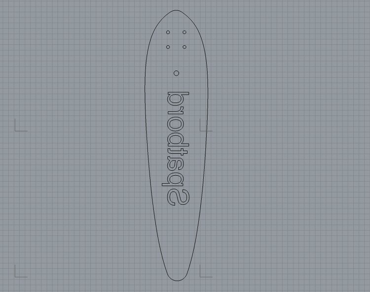
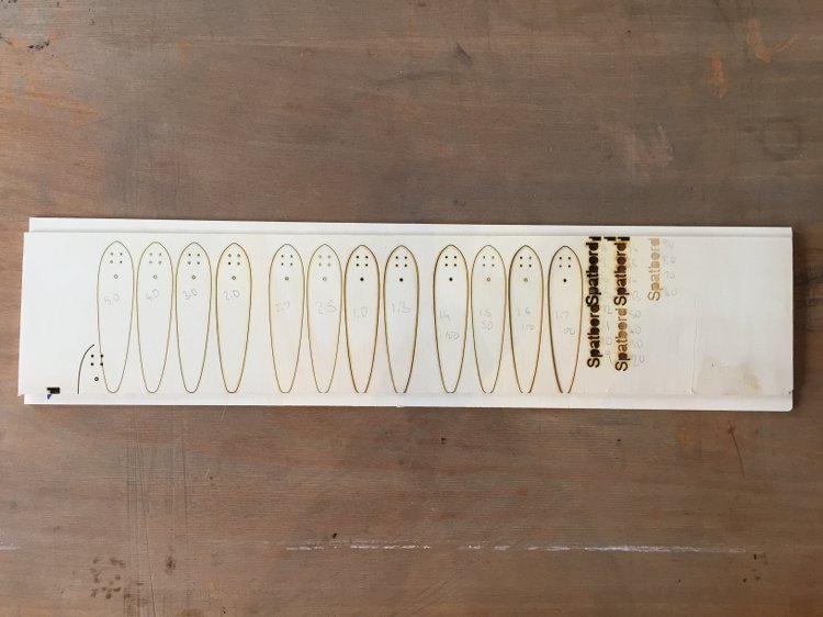
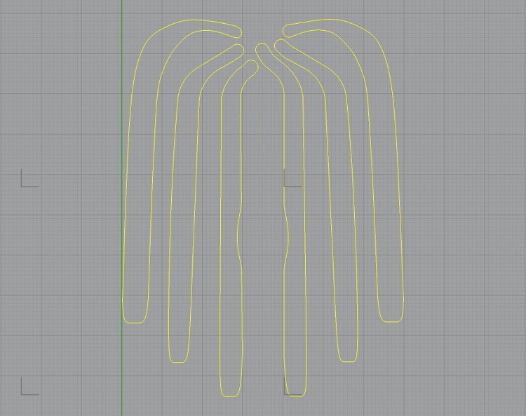
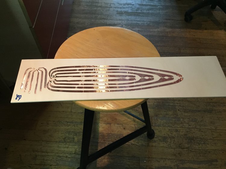
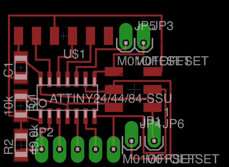
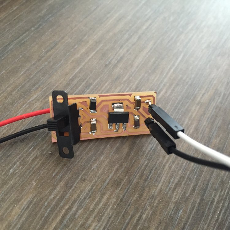
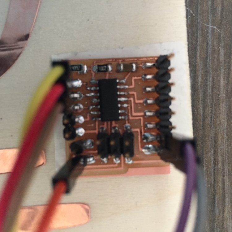
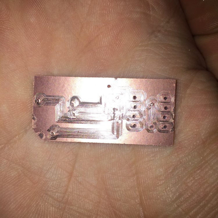
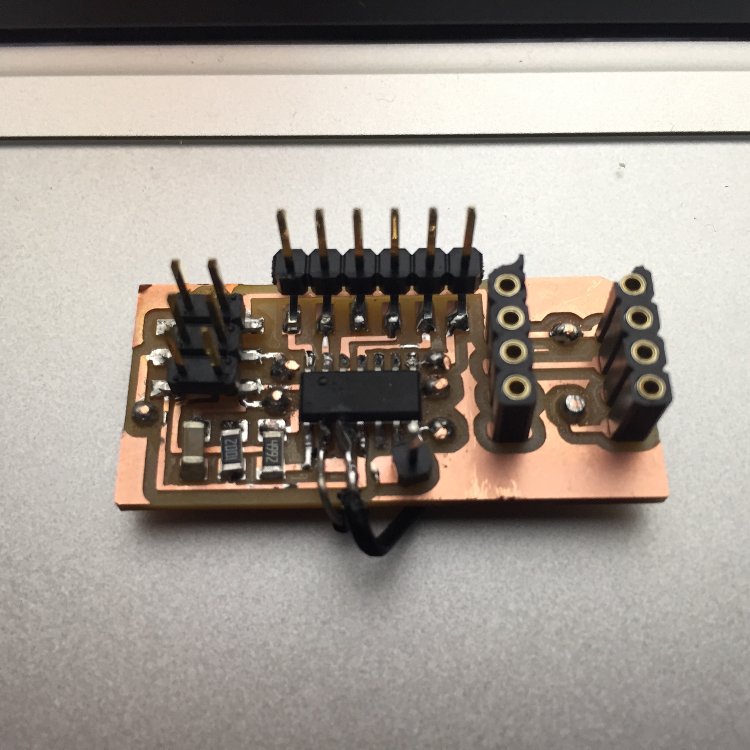
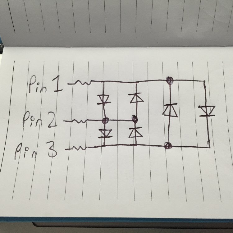
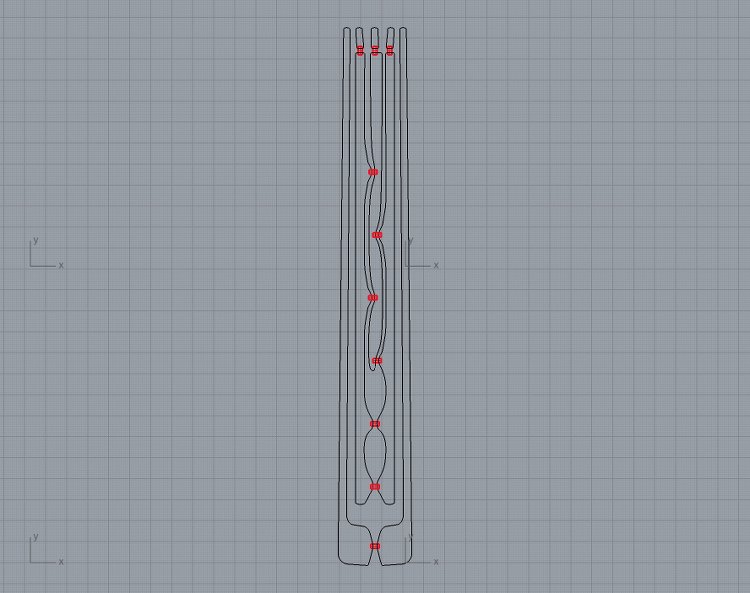
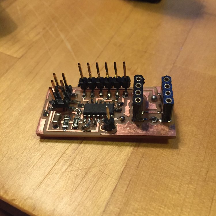
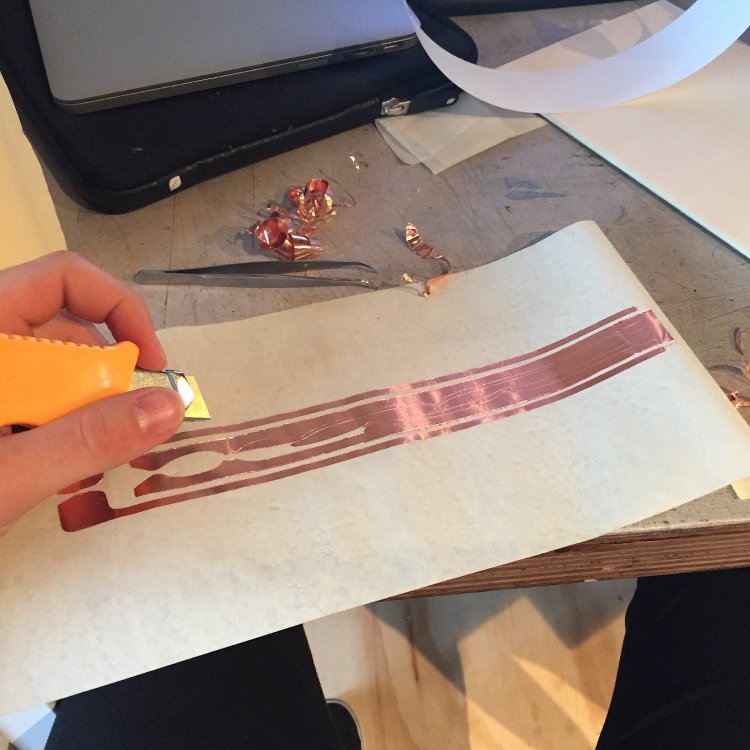
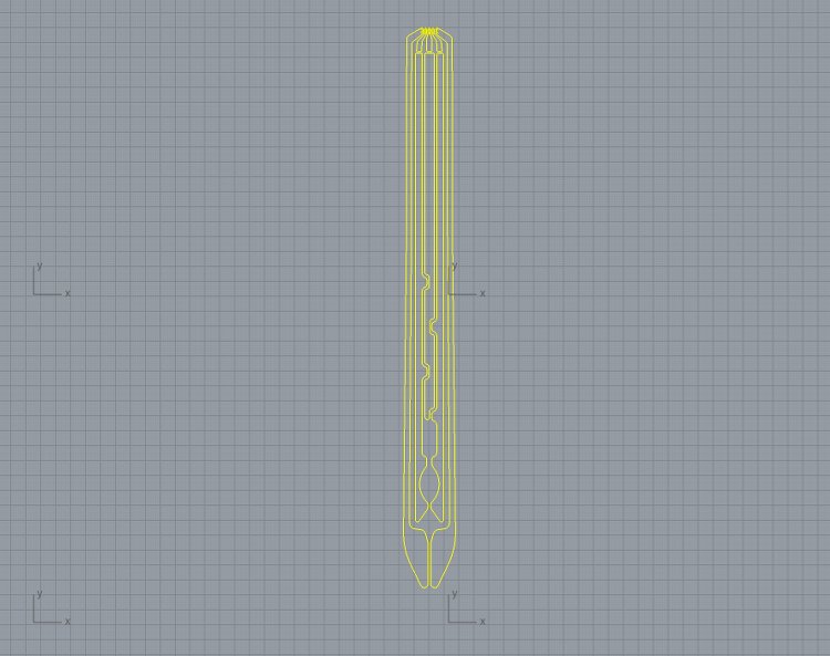
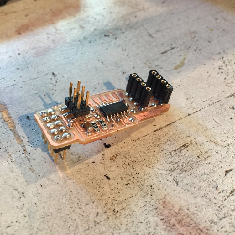
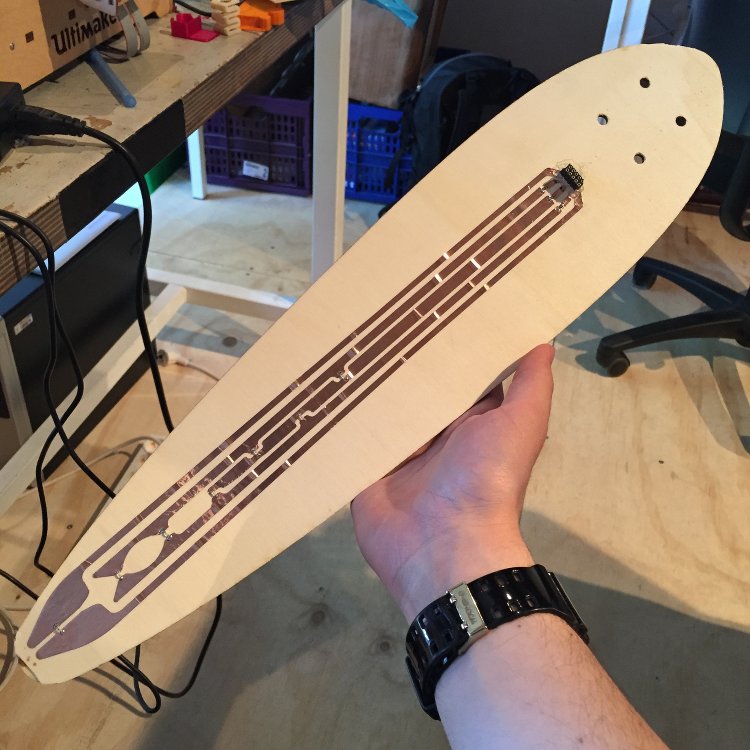
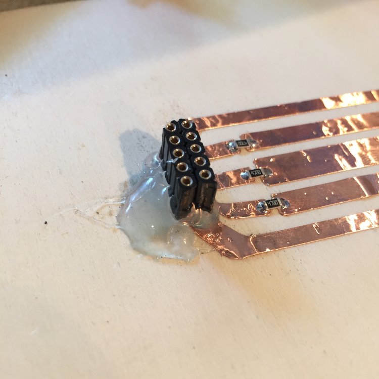
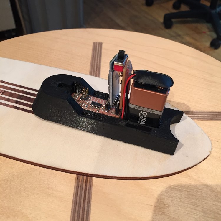
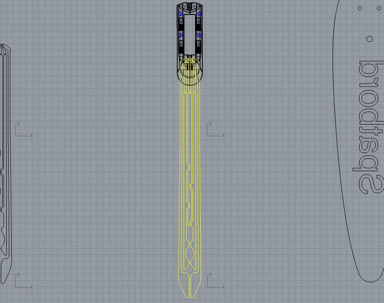
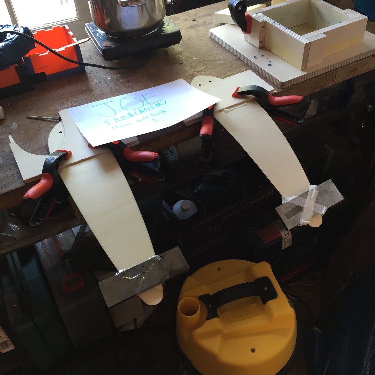
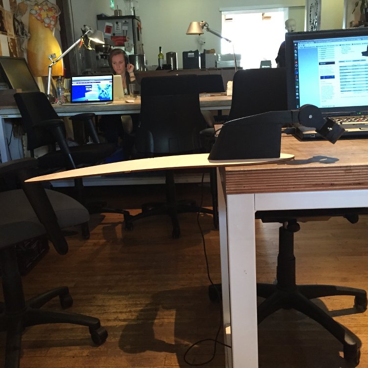
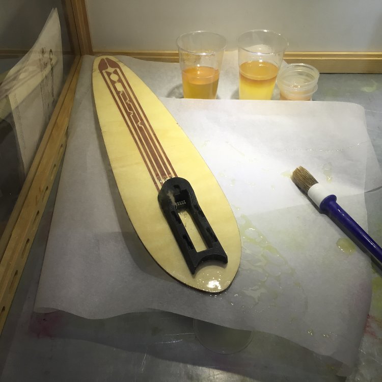
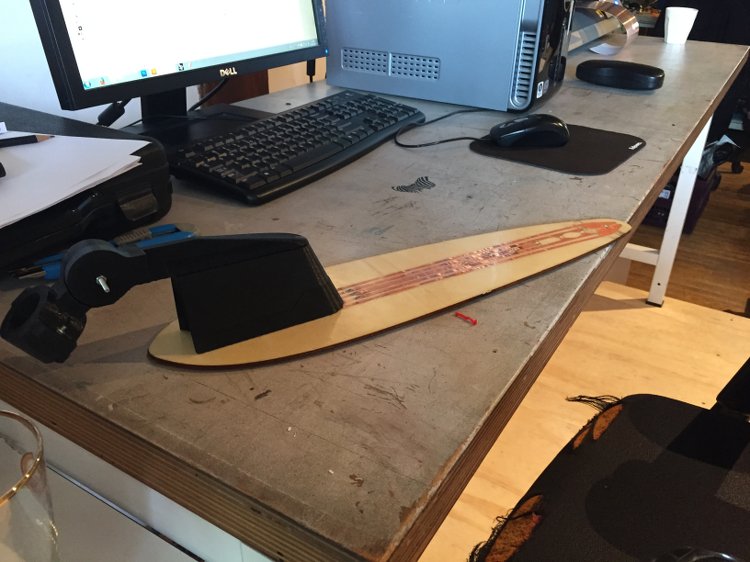
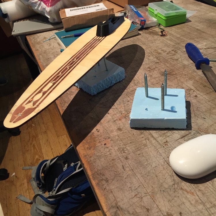
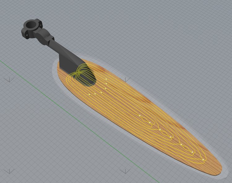
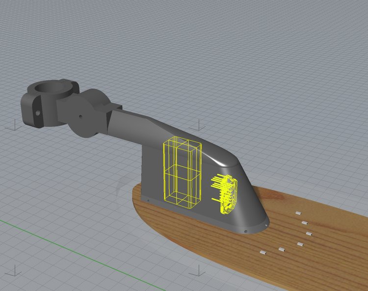
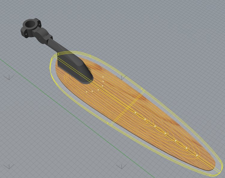
The body of the mudguard will be made of a few elements and include some electronics. A laser cut piece of plywood will provide the core of the mudguard. On the plywood will be a circuit producted in the vynil cutter and controlled by a board housed inside the holding mechanism. The circuit will be a charlieplex circuit to power and LED array and improve the safety of the biker. There will also be a phototransistor to activate it automatically.


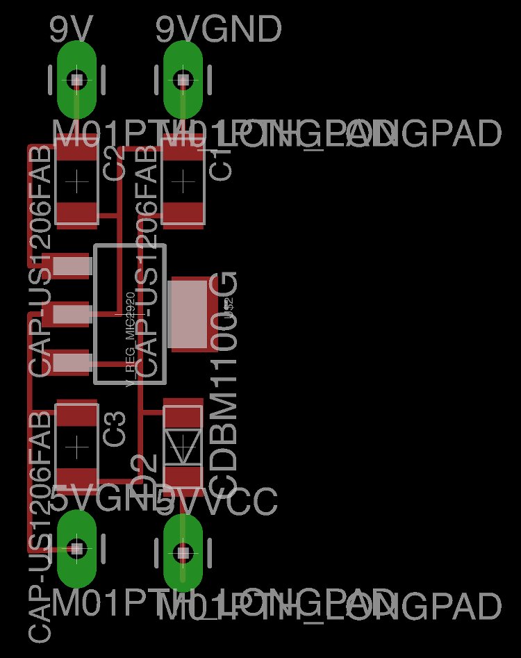
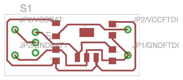
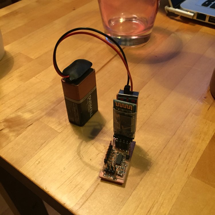
Regarding powering the device, a simple 9V battery housed in holding mechanism will suffice for this prorotype. More advanced methods of powering a circuit can turn into another project all together! This is also where the board controlling the LED array wil be housed.


Weather proofing the fender is a challenge. My initial thought is to make a mold and cast the fender in epoxy resin. This will made it completely weather proof but impossible to repair if the LEDs or phototransistor fails. A further think may be required.


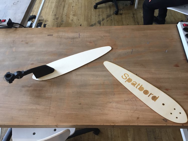
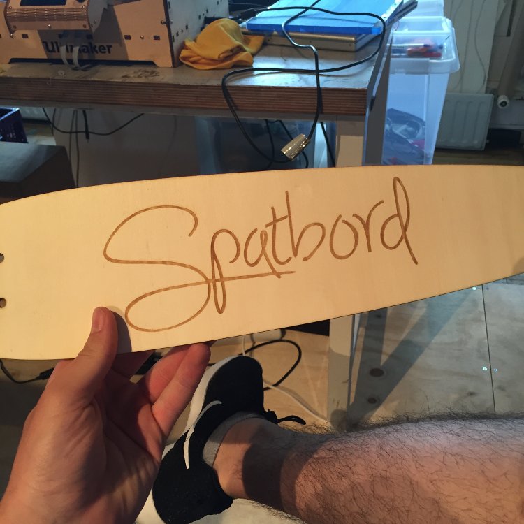
Another question was what to call this thing! As I am Brit doing the academy in Amsterdam, I thought it would be appropriate to call it the local name. The Spatbord!


Getting going!

There are so many tasks I could have picked from for this, I chose to rekindle my 3D printing skills as it has been a while and got to printing the holding mechanism. I had the 3D models ready from the above design and so all I needed was a little time to print them (little being a complete lie, it took hours!).


I printed the parts from in the order shown in the picture from left to right. This took two days of printing at the lab plus a few hours of surface finishing. I chose a layer height of 0.1 mm for the parts.


The joints I made to fit the parts together went together pretty well after a bit of sanding and filing. One big issue I had was that the support structure for the board housing was extremely dense and required a lot of work to remove. But after that it was all good and the 9V battery fitted!


The next step is to produce the board that is designed to fit in the mechanism. I have already made a design for this but I doubt it will be the final design. Either way it will be good to have a "practise board to fit inside.

Check out the designs here


Making a board

So I designed a board which would let me link a few components up but still be small enough to fit inside the housing. I made sure it would fit by making a 3D model of it in rhino. This can be done by exporing a 2D DXF of your board and then extruding the relevant parts in rhino.


Then it was time to mill and solder the board. This was a straightforward process:


Soon after the board was finished, I realised I had put the resistor for the reset pin in the wring position and that a different regulator would be more suitable so I will come back to it later.

Check out the Eagle file for this here

Now I have to look at laser cutting the core of the mudguard.


Time to laser cut!

Preparing the design file for this was a little time consuming. It required quite a lot of work to get rid of double lines and uncecesary lines.


Before I went and cut this, I needed to get the exact values I wanted to use for cutting and engraving. So I gto some nice 3mm plywood and started testing.


for cutting the material, I found that a speed of 1.6 and power of 100 was best then for the test I used a speed of 90 and a power of 100.

For the first cut I forgot to flip the vectors so that the text wasn't mirrored so I did one more and have two cores. After a bit of filing I got the 3D printed part to fit.


Using the vynil cutter

To start off I made a test file in Rhino and started to experiment with the settings of the Vynil cutter. In the end, with the help of classmate, Frank, a force of 80 and a speed of 1 cm/s was sufficient.


I then cut the traces I would be using and stuck them to a test piece of wood, soldered on some LEDs, resistors and pins and tested them:


My design of the traces lets me control 6 Leds using 6 pins. Two LEDs share two pins but are connected with opposite orientation. Similar to Charlie plexing. I am going to redesign the traces using proper charlie plexing. That way I will only need 3 pins.


More 3D printing

Emma, our instructor had delivered a sample of PolyMax PLA filament for our 3D printer. Compared to the filament we normally use, PolyPlus PLA, this has 9 times the impact resistance. I had to try it out!

I noted in my last batch of 3D printing that it would be better to use a boolean union to join two of the parts together and print them as one:


Doing this would save time and improve the quality of the parts printed.

Before I started, Emma and I levelled the bed. This ended up being a rather time consuming task. At first we used a level to try and level the bed but this didnt prove accurate enough:


In the end we followed the tutorial provided by ultimaker and got a better (but not perfect!) result.

I set the printer to work. I reduced the fill density from 80% to 50% this time because the filament is so much stronger. In about 4 hours it was finished!


Like with the other parts, a bit of filing was required before fitting:


I prefer this filament not onyl because it is stronger but also it has a nice bit of flex to it.


Second board design

Now I thought was a good time to work on a redesign of my board. This time I will design two seperate boards. One to regulate the voltage from a 9V battery to 5V, and one to control the LEDs and phototransistor.

I came up with the following designs:

To power the board:


For the board itself:


For the power board, my classmate, Shirley, and I designed the schematic. We arranged the components individually and in the end I went with her design also as it had a better layout:


We milled and soldered our boards with no major issues. I burned the bootloader and was ready to start programming.


My next tasks are to program the board, link it to the vynil traces I cut and test


Programming the board

For my first bit of code I opened up the Arduino example "Blink". I changed it accordingly and discovered that one pair of LEDs were faulty so I adapted it like so:

void setup() {
 // First pair of LEDS
    pinMode(9, OUTPUT);
   pinMode(8, OUTPUT);
 // Second pair of LEDS
    pinMode(5, OUTPUT);
   pinMode(3, OUTPUT);
}


void loop() {

  digitalWrite(9, LOW); 
  digitalWrite(3, LOW);
 
  digitalWrite(8, HIGH);
  digitalWrite(5, HIGH);
  
  delay(100);             
   digitalWrite(9, HIGH); 
  digitalWrite(3, HIGH);
  
  digitalWrite(8, LOW);
  digitalWrite(5, LOW);
  
  delay(300);    
}


Here is the code working here:


Next I tried to get the phototransistor working. Sadly my voyage into this was cut short as I connected it to the wrong pin on the microcontroller. As a result, I need to redesign the board and take another stab at it later.


A better board

Before I go onto redesign the traces, I want to make a better designed board. The improvements I wanted to make were:

Include female pins for the HC-05 bluetooth module and the 9V to 5V board.
Have less pins sticking out of the board.
Make use of a double sided design.

I came up with the following design and went on to mill it and solder it.


It took me two attempts to mill the board. The bottom side failed to mill through even after three attemps. First I adjusted the cut depth from 0.2 to 0.25 mm. Then I retapped the baord to make it more stable. Lastly I set the cut depth to 0.3mm. After all this the underside of the board looked like this:


So I took the painful decision to start from scratch and even change the plate. While soldering the board, I noticed that I forgot to connect the RX and TX pins for the bluetooth module. I soldered some jumpers but will have to fix it later.


I burned the bootloader so I can start coding the board. First though I need to fix the design error and redesign the traces.


New traces

My first set of traces let my control 6 LEDS using 6 pins. My redesign will enable me to do the same with three pins using charlieplexing:


I came up with these traces in Rhino. However, I want to refine the design more before cutting them:


Now I need to fix the design of my board and work on some code!


An even better board!

I fixed the design of my board by connecting the communication pins for the bluetooth module and rotating the female pins 108 degrees as it will fit better:


I then went on to mill it and solder it (with no hickups!):


Here it is hooked up with the Bluetooth module and 9V to 5V board:


The switch needs resoldering but I wish to spend some more time on that and potentially find an alternative switch.


Charlieplexing traces

Now it was time to cut my new layout of traces (but not my last design of them!). This time I used a force of 90 instead of 80 (it turns out I needed to replace the knife). After a bit of weeding they were on:


With the help of Zaerc, our electroncs guru, I had the following code written up which changes the blink speed of the lights depending on the value given from the phototranssitor:

TODO MAKE VIDEO OF THIS

I now know that my hardware and software funstions. I now need to do a final design of the traces, work out how to secure the connecting pins, redesign the board housing and redesign the laser cut.


Prepping final design files

Instead of following the workflow of "design, make, design, make, design, make", I'm going to change it to "design, design, design, make, make, make".

Here is my final deisgn of the traces:


Here is my final board design:


Here is my final laser cutter design:


And here are the new parts for the holding mechanism:


Producing the designs

First thing I did was to begin printing the lower board housing. Then while that is printing I can mill the board, solder, and catch up on documentation. Here is the board all finished:


Not long after, the 3D print was also finished:


I then sent the upper half of the board housing for printing and used the time to laser cut, vynil cut and solder:


I used the same procedure to cut the traces and to laser cut the wood. The only addition is the female pins which the board will connect to. I soldered them then used a glue gun to hold them firm.


Seeing as my latest hardware was ready for testing, I thought I would get straight to it. You can see it all happen below:


By this time the three parts I needed to 3D print were ready so I fitted them to the Spatbord:


One minor design flaw is that the resistors need to be moved further down as the rest under the board housing. This is a quick fix with the traces design:


Playing with the laser cutter

In the middle of all this work, I thought it would be good to change the font of the "Spatbord" logo for my next laser cuts. I used this text generator to make a more artistic font:


As it was a PNG image, I couldn't add it into the Rhino file. Instead I added it just before the laser cutting job in adobe Illustrator. The end result looked much better!


Adding a bend

Now I has a few laser cuts to experiment with, I soaked two of them, clamped them to the edge of a table and added a 500 gram weight to the end.


I left them over night and removed one of them to see the result. It had a very slight curve, less so than I thought it would. But it looked pretty nice:


I added the traces and components then went on to coat it in epoxy resin. This is an edxperiement and will wait over night to see what happens:


I have had to secure the lower board housing with the resin too so I will print another one. I should try to design the part so it can be removed and not rely on gluing. Perhaps a few screws may be required.


Further developments

After leaving the epoxy to set, I took it out of the ventilation cabinet to see the result:


The expoxy added a few nice things to the item. It darkened the wood slightly and made it stiffer. The only downside was that the curve in the wood was pretty much gone. It was going to need more coats to improve the surface.

I then went to check on the other board that I left to dry after soaking and clamping it. This time the curve was a bit steeper:


I gave it the usual make over with the traces and components and it wa sready to also be coated in epoxy. First though I needed to do some 3D printing. I printed two more lower board housings and changed the filaments during the jobs to add some more colour:


The first one ened up breaking so it won't be used. The quality of the prints werent as good as the first one. I have put this down to the fact that I was using a different machine with different filaments.


A second coating of epoxy

Now all the parts were ready, I prepared to apply a second coating. I made some make shift stand for the boards to dry on using scrap foam and screws.


I then applied the epoxy and left them to cure in the ventilation cabinet:


Final Assembly

Once the curing was complete I could assemble a working prototype and test it. I went ahead and did so. I also added some code which would turn off the lights all together when the surroundings get above a certain brightness. Here is the latest code:


#include  <SoftwareSerial.h>  
#define RxD 9
#define TxD 10

#define DEBUG_ENABLED  1
boolean state = false;
SoftwareSerial blueToothSerial(RxD,TxD);
unsigned long next1;
unsigned long next2;

void setup() {
    pinMode(4, OUTPUT);
  pinMode(5, OUTPUT);
  pinMode(6, OUTPUT);
  pinMode(7, INPUT);
  
  pinMode(RxD, INPUT);
  pinMode(TxD, OUTPUT);
  setupBlueToothConnection();
  next1=millis()+0;
  next2=millis()+500;
}
 void setupBlueToothConnection()
{
  blueToothSerial.begin(9600); //Set BluetoothBee BaudRate to default baud rate 38400
  blueToothSerial.print("\r\n+STWMOD=0\r\n"); //set the bluetooth work in slave mode
  blueToothSerial.print("\r\n+STNA=HC-05\r\n"); //set the bluetooth name as "HC-05"
  blueToothSerial.print("\r\n+STOAUT=1\r\n"); // Permit Paired device to connect me
  blueToothSerial.print("\r\n+STAUTO=0\r\n"); // Auto-connection should be forbidden here
  
  delay(2000); // This delay is required.
  //blueToothSerial.print("\r\n+INQ=1\r\n"); //make the slave bluetooth inquirable 
  blueToothSerial.print("bluetooth connected!\n");
  
  delay(2000); // This delay is required.
  blueToothSerial.flush();
}
//unsigned long next;
 int sensorValue;
void loop()
{
  sensorValue = analogRead(7);
  blueToothSerial.println(sensorValue);
  next1 = millis()+100;
if(sensorValue < 200)
{
  digitalWrite(6, LOW);
      digitalWrite(5, LOW);
      digitalWrite(4, LOW);
}
else{

  if(millis() > next1)
  {
     sensorValue = analogRead(7);
     blueToothSerial.println(sensorValue);
     next1 = millis()+100;
  }

  if(millis() > next2)
  {
    if(state)
    {
      digitalWrite(6, LOW);
      digitalWrite(5, HIGH);
      digitalWrite(4, HIGH);
    }
    else
    { 
     digitalWrite(6, HIGH);
     digitalWrite(5, HIGH);
     digitalWrite(4, LOW);
    }
    state = ! state;
    next2 = millis()+sensorValue;
  }
}
}   


I also used processing to interface the data being sent to my laptop. It makes a nice addition for the final presentation. Here is the code for it:


import processing.serial.*;

Serial myPort;        // The serial port
int xPos = 1;         // horizontal position of the graph 

//Variables to draw a continuous line.
int lastxPos=1;
int lastheight=0;

void setup () {
  // set the window size:
  size(1280, 780);        

  // List all the available serial ports
  println(Serial.list());
  // Check the listed serial ports in your machine
  // and use the correct index number in Serial.list()[].

myPort = new Serial(this, "/dev/tty.HC-05-DevB", 38400); 

  // A serialEvent() is generated when a newline character is received :
  myPort.bufferUntil('\n');
  background(0);      // set inital background:
}
void draw () {
  // everything happens in the serialEvent()
}

void serialEvent (Serial myPort) {

  // get the ASCII string:
  String inString = myPort.readStringUntil('\n');
  if (inString != null) {
    inString = trim(inString);                // trim off whitespaces.
    float inByte = float(inString);           // convert to a number.
    inByte = map(inByte, 0, 1023, 0, height); //map to the screen height.
  // Sets 'a' to 27
    //Drawing a line from Last inByte to the new one.
 

    stroke(255,255,255);     //stroke color
    strokeWeight(3);        //stroke wider
    line(lastxPos, lastheight, xPos, height - inByte); 
    lastxPos= xPos;
    lastheight= int(height-inByte);

    // at the edge of the window, go back to the beginning:
    if (xPos >= width) {
      xPos = 0;
      lastxPos= 0;
      background(0);  //Clear the screen.
    } 
    else {
      // increment the horizontal position:
      xPos++;
    }
  }
}


Here is all of it working together!


The project is now at a stage where it can be presented. However, one or two things need to be done. The mechanism that is supposed to attatch to a seatpost needs to be altered and I feel I should take the hardware and coding further than is current.


Recent additions

I have altered the Processing code a little so that the mudguard can be changed between different modes. These are three speeds of blinking and an automatic mode. The latest Processing and Arduino code can be found here.