Week 3 - Computer Controlled Cutting

This week of the Academy covered the laser cutter and vynil cutter. We learned about the principles on which they work, what their uses are, the limits of their usage and, most important of all, safety precautions. In this weeks entries, I will up the size of my pictures slightly for easier viewing. My changes last week have beefitted me well so I will keep the same format for documenting my work and how I (attempt to) manage my time.

This weeks assignment:
Design and cut a press fit construction kit out of industrial cardboard.


12th February 2015 - First Laser Cut!!

Ah, press fit construction kits, one of the many beautifil things that a Fab Lab can produce. It is also a very tricky process to design. You continuously need to picture how the joints will fit together in your head to help ensure success. But once cut, it makes it all the headahes produced worth while!

Last week while practising with CAD, I had a mini apiphany and thought that it would be great to make an object that could help me model a way of generating electricity from a bike. So I got to work on modeling such an object and look at how it can be made using press fit contruction (which would give me a good start on next weeks assignment). Below is the work I did in SketchUp to help visualise my idea.

My idea is that I can make a frame to support a bike wheel and allow it to spin freely. Then modular parts will allow me to position metal coils near the perimeter of the wheel. With magnets correctly positioned on the wheel, I will be able to research how much kinetic energy \i can convert to electrical energy from the wheel.

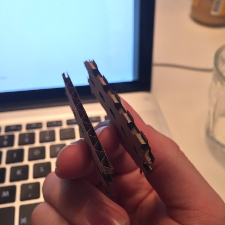
In wednesday's lecture, Neil mentioned that we should make our press-fit construction kit from industrual cardboard. Hopefully this will be strong enough to support the wheel and a few magnets. If not I will need to reconstruct using a different material. It will be worth the effort of sucessfully making this as this will contribute nicely to my final project.

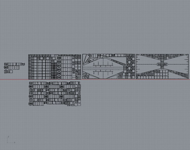
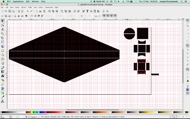
The nest thing I did was draw out the parts using Inkscape (I also used Rhinoceros for practise). While a tedious process I got the job done. However, today I realised I should be more efficient with my material usage and so started from scratch (almost). Take a look below.

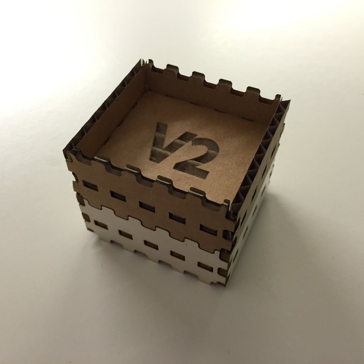
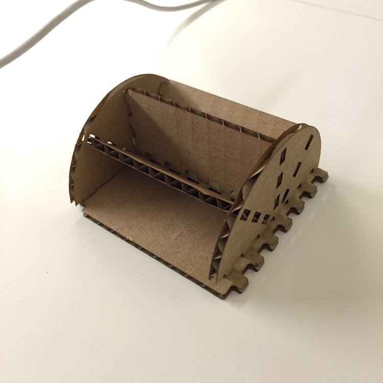
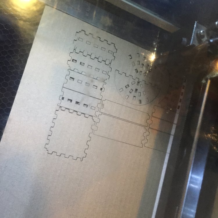
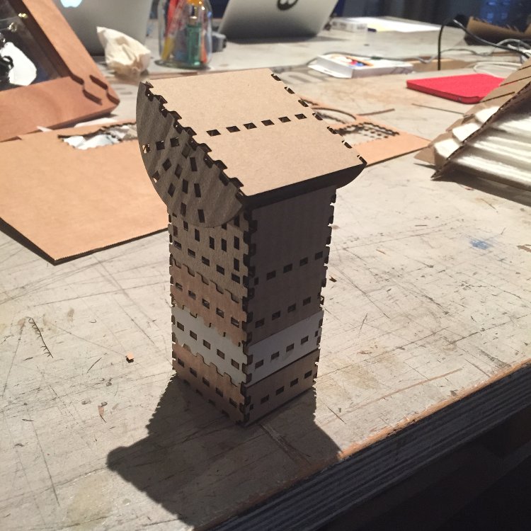
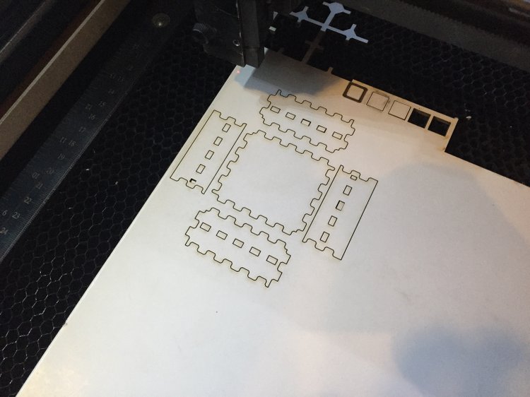
It is only half of the parts I need but the rest wil follow shortly. An opportunity came up to use the laser cutter today, so I made the most of it and added some finger joints to one of my modular pieces. I took a small risk with making a whole modular piece without checking if the joints would work. But, I carefully scrutinised my drawing for any flaws eventually giving it the go ahead. We then found some 3mm MDF (same thickness as the industral cardboard but denser) and cut out the pieces. Once cut the pieces all fit together nice and snug! In fact, very snug. I was curious as to why because I was afraid the complete opposite would occour. Before I explain why, heres a few pictures of the modualar piece.

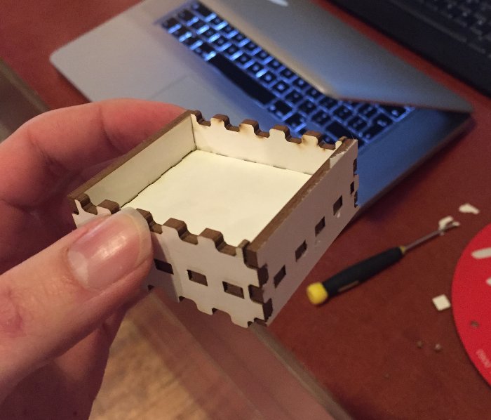
So yes, as I was saying, the reason it was so snug was due to a design flaw that I had failed to notice. The holes cut to fit the centre piece didn't quite line up relative to each face, but varied only by less than a millimetre. For me, I have found this as a great little discovery as that small defect is what really holds all the pieces together so well! So it is a design flaw that I will keep for the real thing and make good use of in future designs.

So to conclude today's antics.... I am very satisfied woth the work I have comlpleted so far as it had put me a step or two ahead, which is never a bad thing. Now I know that my design of press fir joint works in MDF, I just need to test it on cardboard then go onto cut out the rest of my design.


13th February 2015 - Developing my press fit designs

So today we has a session in the lab which was all about the laser cutter. We learned how to prep it and clean it (It get dirty pretty often). We also looked at ideal cutting preferences for the cardboard we would be using. The preferences we need to adjust when using the machine are as follows:

Speed of laser:- pretty self explanatory, this is important as too slow a speed increases the changes of burning the material.
Power of laser:- again, pretty self explanatory, there is a balance to be had between the these two preferences. The lower the power, or higher the speed, the shallower the cut. I could even just become an engraving. The slower the speed or higher the power, the deeper the cut. These settings will vary greatly depending on the material.

For cutting cardboard, the speed should be set to 6 and the power to 100 (these units have a maximum of 100). For engraving cardboard, the setting should be both set to 100. That means the laser won't have enough time to cut though the material, it will only be able to burn away the top layer. below you can see a cardboard version of the part that I made yesterday. I have proudly named it V2!

I was very pleased with the result of this cut! It fitted together as well as the MDF version, was still sturdy and even more featherweight! Following this success I pushed on to try and get another one of my modular pieces cut and assembled before the day was out. But unfortunately it wasn't meant to be, I ended up with horrible errors! (well it was Friday the 13th after all!) I designed the shapes on Rhino this time. So much more pleasant to use than Inkscape! Exported the file to Adobe Illustrator which is what the lab needs to cut it. I set the preferences correctly (baring the engraving I had planned to put on it) and set the machine to work. After cutting and assembling I discovered my fatal error....

As you can see, the cross section at the base is too long! (well actually it was the opposite, but this way displays it better) So after the session, I stormed down to the library and redesigned it and completed the rest of the design for the model I made on SketchUp. I am 99% sure it will all fit perfectly but I will still do some test cuts. Below is the design on Rhino.

All that is left to do is make lots of copies of the modular parts and make sure I use my material as efficiently as possible to reduce wastage. I am expecting that the main part of my design will need a stronger material than cardboard due to the forces that will be involved. I will have a stronger material at the ready just in case this happens. I want to use the cardboard first because Neil wanted us to try everything in cardboard then recreate any designs in a different material if we wanted to. Also, it will be great if the cardboard does do the trick but I want to experience cutting different materials with the machine. (I will be happy either way!

One other thing I must do is find where I can source some magnets, coils of wire and a bike wheel so I can actually put my design into use.

Click here to download the design file.


15th February 2015 - First Laser Cut!!

So today while looking at my V2 model and noticed that the grain of the card board plays a big part in strength. Because of this I am going to make sure that the grain goes down the sides of the modules and not across. In the picture below, the part on the left has the grain going down and the one on the right going across.

However, as ideal a thing as it is to consider this, it is difficult to implement when considering how to fit as many of these parts into a given area as possible to save on material. Because the extra strength gained is neglible for my uses, I will not make it a priority. So I have fitted as many parts in the space given as I can.

Before I went to cut this, I cut some test pieces to be sure they would work. They all fit pretty well! The piece that sits at the top is quite loose, but not too loose. It also sits nice and steady at a range of different angles; perfect for what I want to use it for. Therefore I chose to not alter the design any further for the sake of time. But like I said, they will serve their purpose well. Below, you can see the parts being cut and the final result!

One other thing I had to do was clean up the parts of any loose bits which shouldn't be there, this was gonna take a while so I thought I would try out a time lapse video of some of it. Take a look below.


17th February 2015 - Completed My Press Fit Construction!

Today saw the completion of my press-fit construction kit! I had some issues with double lines in my designs (meaning the laser cuts the same line twice thus wasting valuable time!). There wasn't much I could do about this so I deleted some of the double lines but not all of them as the process of cleaning the design up could end up taking longer. I cut the final parts of my design, the structure that houses a bike wheel. To my surprise the structure held together; even when the wheel was spun. It is a good prototype but I would still need to make some modifications.

The structure is pretty fragile so I will need to design tighter fitting joints and include more parts to support the structure. I would also change the material to something more durable such as MDF. That will make the structure more reliable for when I attempt to model a generator.

I am happy with the work I have done on this week's assignment. I was able to create some pretty stable modular parts which are put together using press fit construction and prototype a larger press fit structure which can make use of them. The only thing I would have also liked to have completed was a second prototype of the larger structure (which is still going to happen). One thing I could improve on is my design work. I really need to watch out for double lines and so on. This issue was partly cause because I am not used to having to consider double lines in my CAD work. I believe this issue will sort itself out as I become more experienced.

Bring on next week's assignment!