- Home
- My Assignments
- Project Management - Complete
- Computer Aided Design - Complete
- Computer Controlled Cutting - Complete
- Electronics Production - Complete
- 3D Scanning and Printing - Complete
- Electronics Design - Complete
- Embedded Programming - Complete
- Computer-controlled Machining - Complete
- Molding and Casting - Complete
- Input Devices - Complete
- Output Devices - Complete
- Composites - Complete
- Networking and Communications - Complete
- Interface and Application Programming - Complete
- Applications and Implications - Complete
- Mechanical and Machine Design - Complete
- Invention, Intellectual Property, and Income - Complete
- Final Project
19th February 2015 - Making Our Boards
This morning we had a more in-depth class about the board we would be making. We had a quick recap of what Neil mentioned in yesterday's lecture. As this weeks assignment is about learning the processes we need to use rather than being crative, I will docuement the process in as much depth as possible. The milling machine used is called the "Roland Modela".
Milling The Board
Here I will do a write of what we had to do to set up the
machine and mill the board:
First, I turned on the computer that will program the machine
to do the job and logged into the system. Secondly, I turned on the
milling machine.
Now that the machine is turned on I could prepare the plate from
which I was going to cut out the board. There is a base which you need to
unscrew from the machine. To start this process, press the view button
on the front of the milling machine. This will move the cutting tool out
of the way and bring the base to the front of the machine. Unscrew the
base and ensure that the sacrificial layer (the layer that protects
the base when doing a deep cut) is free of any tape or pther plates.
Use double sided tape to secure your plate to the sacrificial layer
and srew the base back onto the machine.
Now we need to find the files that we will use to mill the board.
There are two, one to mill the traces and one to cut out the board.
They are both PNG files that need to be converted to the machine's ".rml"
format. To do this in this case, open the terminal and type "fab" to
bring up the tool that will do this. Set the tool to open the PNG files
as .rml files and click "make_PNG_rml. A lager window will then pop up.
Click "load .PNG", open the trace file and click "make path" After doing
these procedures the desktop looks like this.
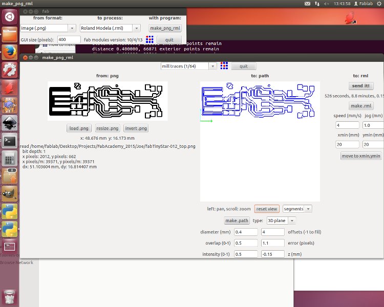
You can see towards the top is the tool opened from the terminal. The
larger window being the tool we use to set up the machine. Also note the
view settings just below the path display in the middle. Setting it to
segments will show the path the tool cuts or traces.
We now have to set up the machine so that it can mill the trace of the board.
I started by preparing the computer settings, but you could also start by
preparing the cutting tool on the machine. There are quite a few settings so
they are listed below.
First there is the, you could say, "mode" of the milling machine. This is
located in the top middle section and has a number of modes the different
modes vary between what you want the machine to do; such as tracing or
cutting. It also varies between what tool you attatch to the machine. For
tracing in this instance I used the "mill traces (1/64)" mode. So this tells
the machine that is it going to mill a trace using a 0.4mm cutting tool.
This will then lets it plan a path which will make efficient use of the
diameter of that tool. The interface then brings up the 6 options at the bottom.
The "diameter (mm)" is the diameter of the cutting tool. This is already set so
there is no need to change it.
The "overlap (0-1)" adjusts how much you allow the path maker to over lap the
paths for a given diameter. For this design we set it to 0.5. It ensures that
an area that is meant to be traced out ensures it is completely traced out and
that the machine doesnt miss a spot. This also affects the time of a job so a
balace has to be found.
The intensity is a setting which doesnt seem to change anything for this use
of the machine. Therefore we did'nt touch it.
"Offsets (-1 to fill)" adjusts the number of passes you allow the tool to make
to mill the trace. Like overlap, a balance has to be found.
"Error (pixels)" determines how closely the path follows the PNG file. Zero
error would make the path perfect meaning a curve would acutally be a very small
zig-zag line. To save time it is good to set the error to something like 1.1.
This means a curve will be made up of less lines will be prepresented by a few pixels.
This will reduce the time the machine takes to do the job with a negligable
sacrifice to quality.
Lastly, in this area of the window, we have "z (mm)". This tells the machine
how deep to mill the trace. For this setting the closer to zero the better. However,
If z is too close to zero, copper that should be milled out will still remain. This
is another balance that has to be found. We found -0.15 mm to be the ideal setting.
Clicking "make .path" as you adjust these settings will update the path and let
you decide of the settings are suitable.
Another important setting is the origin. This is located towards the top right of the window.
They are called "xmin (mm)" and "ymin (mm)". Adjusting these and clicking "move to xmin,ymin"
will show where the machine will start the job from on the base. This is important when using
one board for multiple jobs. Once the desired origin has been found, it is important to note
the co-ordinates down incase you need to run the tool over the same trace again (this can
occour if z has been set too close to zero, for example.).
After adjusting these settings, I prepared the machine itself or milling the trace.
The procedure is as follows:
1. Press the view button on the machine to bring the tool into a position.
2. Check that the tool is the correct one. If not then remove the tool by loosening
the hex screw securing it with an allen key.
NOTE:- It is essential to hold or support the cutting tool at all times with your
fingers when replacing or adjusting the tool. Otherwise it will drop out very suddenly
and you will risk damaging the tool. The cutting tools arent very expensive, but it is
good practise.
3. Inset the 0.4mm cutting tool so that the cone tip is still visible and secure it
using the allen key. Do not over tighten as this will damage the tool housing.
4. Press the view button again to return the tool to its origin position and lower
the tool near the base. This can be done using the controls under the view button.
Leave about 10-20 mm free.
5. Next the tool must be lowered so that it just touches the plate. This is done by
using the allen key again to loosen the srew holding it and tightening it again once
the tool is just touching the plate.
Now the machine is prepared for milling the trace.
One last procedure we must follow is to click two buttons on the larger window in
the desktop. You click "make .rml" an estimated time will show up. Then click "send
it!" and the machine will start the job.
Things to do during and/or at the end of the job
1. At the end of the job, you need to press view so the tool moves out of the way
so you can see what it has cut. You will need to remove the dust and shavings using
a hoover. Then it is very important to check that there is no copper in the paths
that the tool has milled out otherwise a short circuit would occour later on. A useful
feature is that you can also do this during the job and then press view again and it
will continue from where it left off.
2.Lets say you check the work that has been done during the job, and you find that the
tool hasn't cut deep enough. The only option for you is to cancel the job (or just let
the job contine if it is about to finish). To cancel there is a tutorial which involes
using commands in the terminal to cancel the job. I had to make use of it when milling
my board as the origin I had set hadn't been included in the job sent to the machine.
First I needed to press the up and down buttons I used on the machine when positioning
the tool until the light to indicade that the view button had been pressed was flashing.
The tutorial then said to use two commands to cancel a job but I found it to be unecesary
in the end as the machine had appeared to delete the job by itself (less hassle for me!).
I then checked over the settings and followed the previous procedure to send the job to
the machine again (a touch of de ja vu!).
Check out the milling process! (Another time-lapse video as promised)
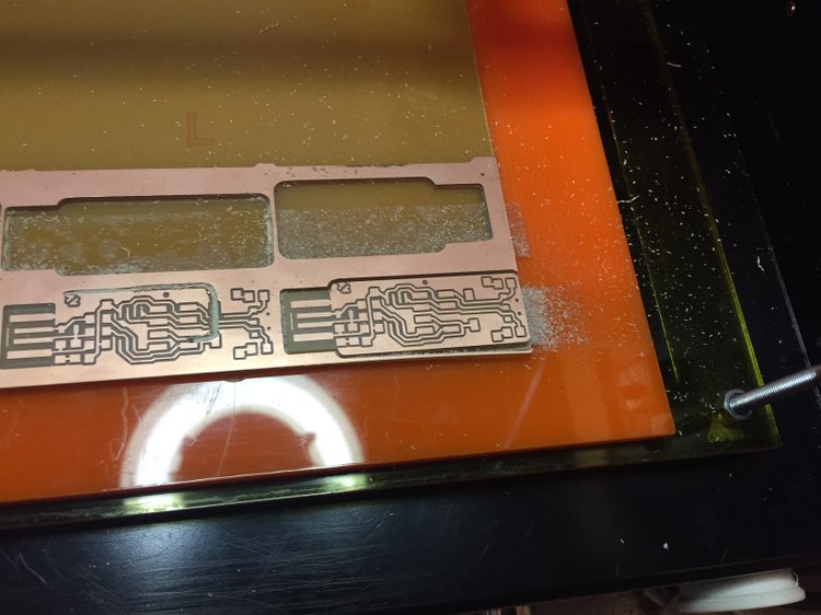
Now that the trace has been milled out we need to follow the same procedure to cut the
board out. I've explained on depth already how to do this so I will just list the basic
steps:
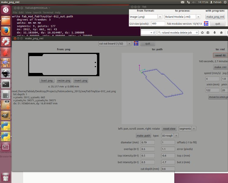
1. Open the cut file
2. Change the mode to "cut out board (1/32)"
3. Go over the settings
NOTE:- There are two additional settings to adjust when cutting all the way through a
board. The "top z (mm)" tells the machine how thick the material is. The "cut depth
(mm)" tells us the incraments in which it will cut to the desired depth with.
Soldering and programming
So now that the board is milled and cut we are left with a nice little board to solder out components to but before we solder the board needs to be washed to get rid of things like grease which would make it a real pain to solder.
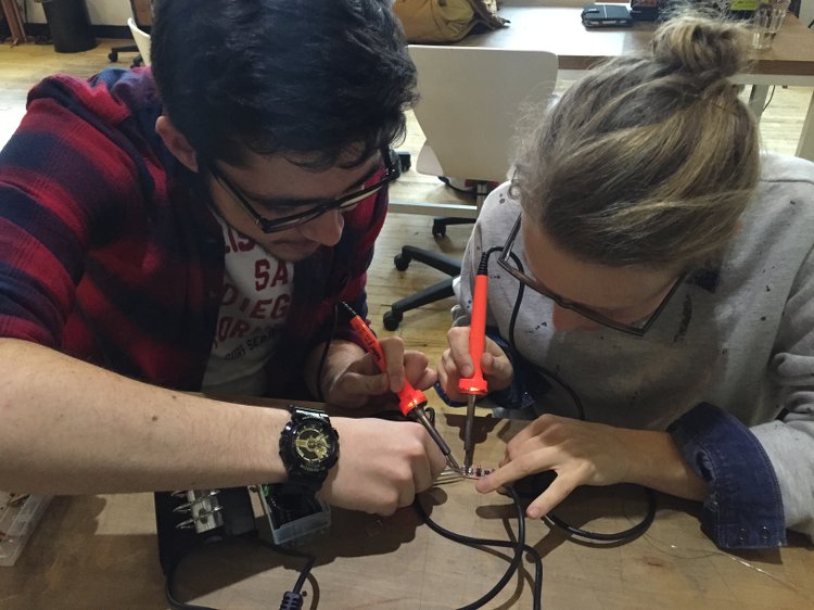
I found soldering the board challenging but not too challenging as I have used a soldering iron before but not for such small components. We had an image of the design on our computers and a list of all the parts we needed to solder to the board. Emma, our instructor, showed us the technique of melting some solder to the board before soldering the component. This then makes it easy to solder the other joints for that component, especially if there are as many as 8.
There was the odd occasion where a component had to be removed after soldering because it was the wrong one. To deal with this we had a heat gun which would melt all the joints attatching the component simultaneously. However, using a bit of team work, we found it a tad quicker and easier to do this. Two of us would each take a soldering iron and melt the joints at the same time.
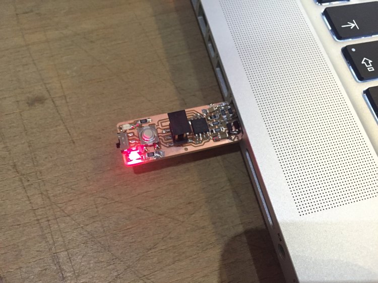
After soldering we used a volt meter to check all the connections and spot any short ciruits. If we did spot a short ciruit we would melt the offending solder and use braided copper wire to wick it up off the board. Once this is done we can start on the road to program it. The first test after debugging the connections is to stik it in a computer and check that the red LED light works. (Mine passed with flying colours of course!)
Next thing we had to do was promgram our programmer using another programmer and running a few commands in the terminal. These are all given in the tutorial. An important thing to do is be sure that the ribbon wire is connected the right way round on the two circuit boards.
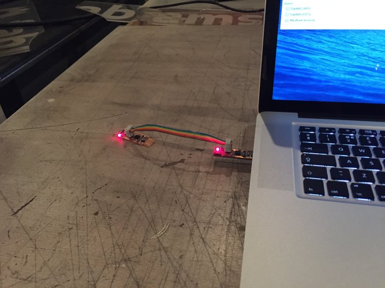
Now this has been done, we can check to see if our newly programmed programmer works by sticking it in our computer to see if it shows up. Unfortunately for me it didn't. After a few attempts of looking for short circuits and going over all the joints it had been declared unfixable. So I had to start from scratch and make another. Fortunately it was second time lucky for me so in the end my board was recognised by the computer. (YAY!)
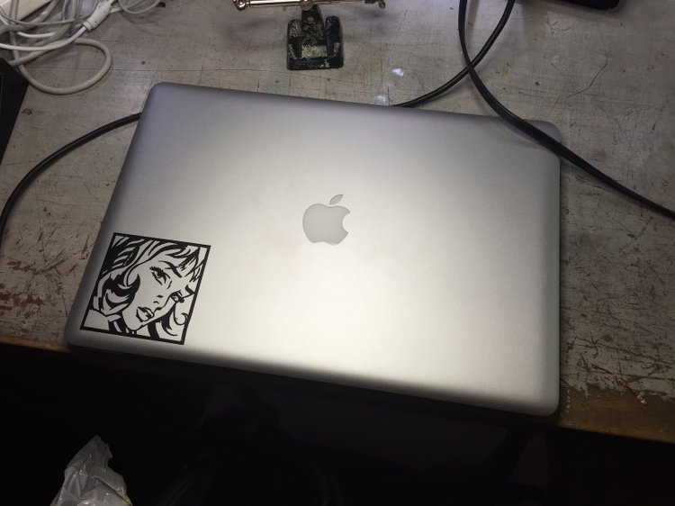
After all the palava of making a secind board from scratch I rewarded my hard work with a sticker for my Macbook. This gave me a chnce to learn how to use the vynil cutter which will probably come in handy later on. I picked a Roy Lichtenstein pop art piece. In the end it came out pretty good. I'll slowly add more pop art pieces.
I am pleased with my work this week as I have completed the assignment with a few days to spare. However, I found some of my documention to be like a long slug of text. Next weeK I want to work on breaking it up more with time-lapse videos as I feel they are the best way of getting across the processes used in these assignments.