Week 12 -Output Devices

This week covers output devices and will be an almost idential work flow to last week. Fortunately it turns out I have already completed this assignment because I used an RBG led as in indicator for a phototransistor. I programed the LED to do something which fufils the requirements for this week. However, I will still design another circuit as in this week we learn how to use microcontrollers to control higher power components.

Assignment:

add an output device to a microcontroller board you've designed and program it to do something


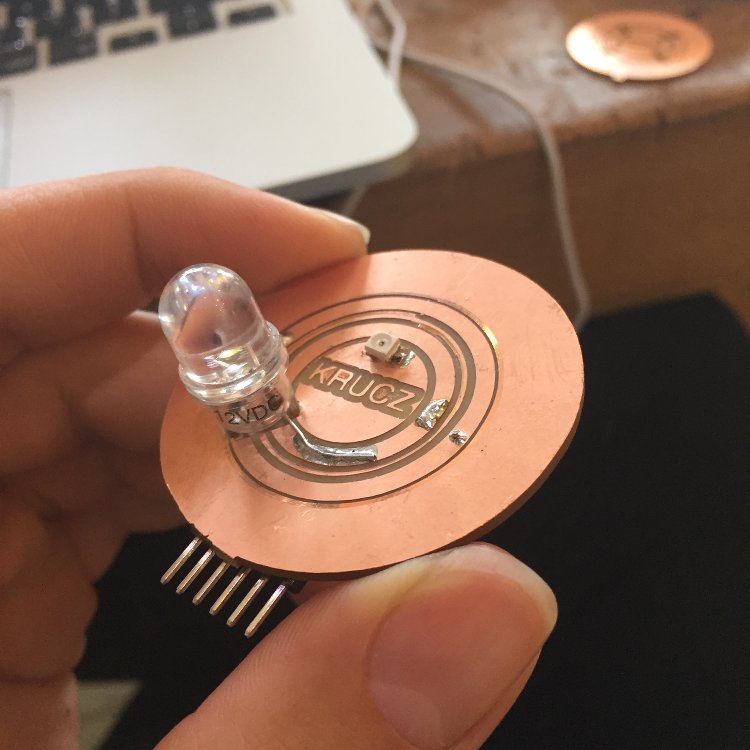
16th April 2015 - Bigger LEDs

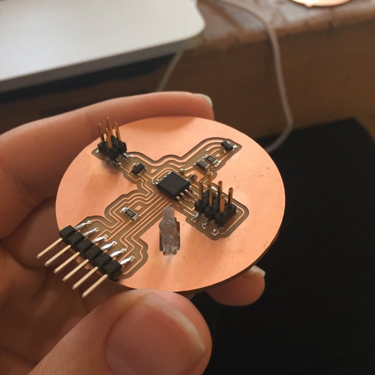
I want to take this assignment as an opportunity to do something towards my final project. I made a light design which I could adapt into a bike light. I am thinking of making a secind version which is light sensitive. This would bring the design closer to being a functional bike light. My main priority though is to get a circuit design which is bug free. If that goes well I will look at designing a housing for it too.

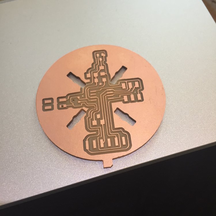
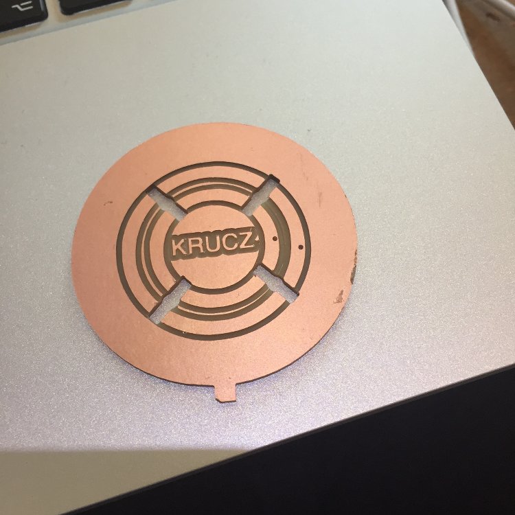
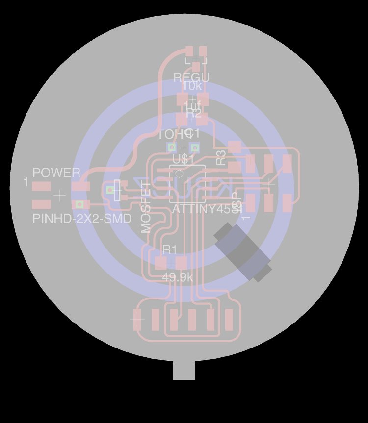
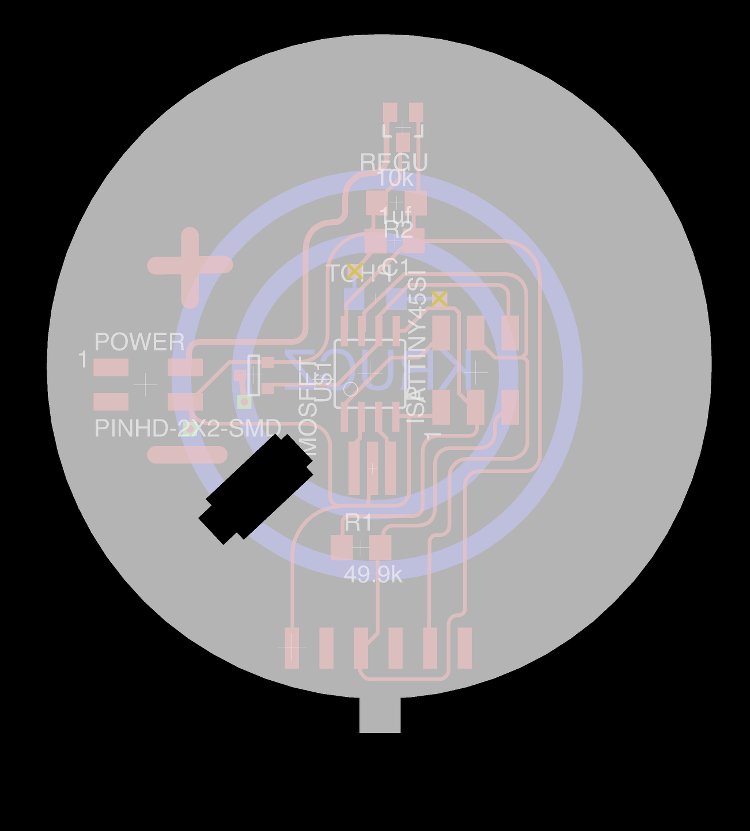
Below is the board I have designed:


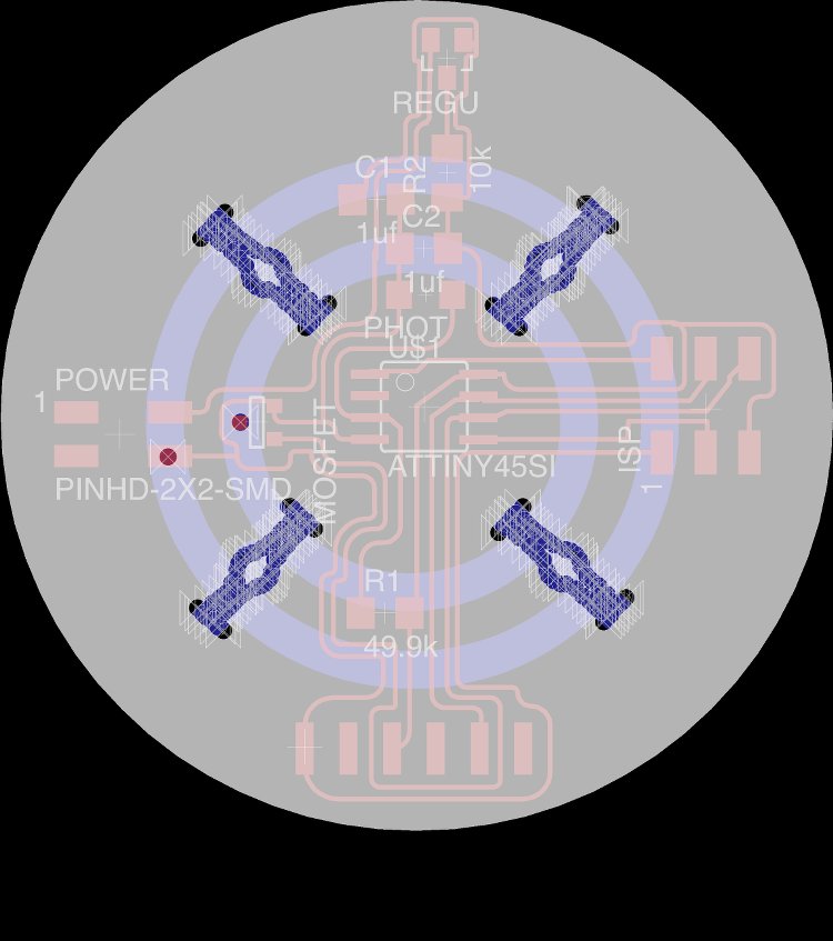
The biggest difficulty I had with this was trying to make some though holes for the LEDs I would be using. I had to rather crudely use the hole funstion in eagle to make the shape and then tidy it up in GIMP. I will try to find a more accurate way of doing it. Unfortunately the modela isn't avaliable until sunday so all I will do between now and then is compile more research for my final project and watch out for any bugs in my design.


19th April 2015 - Board Milled

I milled the board that I had designed but sadly I ran into a few issues during preparation of the job. Some of the traces needed to be repositioned and I also had to lie to the machine a little about the diameter of the tool. Saying the diameter of the tool is smaller than it actually is enables al the traces to be recognised by fab modules. Once fab modules was happy I ran the job. This was the first time I had done a double sided PBB design and a few extra steps need to be taken:

1. The PNG image for the bottom of the board needs to be mirrored
2. Once the top traces and board outline have been cut, it is necesary to file the bottom left corner of the board (once flipped). This means it will sit nice and straight for the next traces job.
3.The orginal co ordinates given by the machine but have 0.8 subtracted from them to compensate for the change in position of the board. (that is assuming that the bit used to cut the board out is 0.8mm in diameter. If not then adjust accordingly.).

Take a look at the board below:


Some of the traces got extremely thin and I decided it would be pointless to solder a board that is doomed to break! I went back to the drawing board to do a re-design.


20th April 2015 - Bigger LEDs V2!

So I have now made a few changes to the design. I removed three of the 4 LEDs to avoid drawing too much power from the supply. I also made some of the traces bigger so that they can handle the power.


I milled this board out and soldered it. Looks rather neat I think!


However I made a horrible error with this board. I linked up the supply the wrong way causing the regulator and mosfet to smoke. Aparently once this "magic smoke" escapes from these components, they are useless. I can replace them but instead I will mill a third (and hopefully last!) version. This one will include a diode to ensure my board won't get damaged if the same mistake happens again.


21st April 2015 - The third version...

So today I spent some time designing a third version of my board, which icludes some further optimisations.


I added a resonator to save the hassle of calibrating the internal clock to a suitable level and added some plus and minus symbols to make it more clear as to which supply wire goes where. All that is left to do is produce this new board and program it.

Thankfully I have some arduino code I wrote in last week's assignment which can be used with a few alterations. I will add this to the documenation once the board is made. The modela isn't avalable until the morning of wednesday's afternoon lecture so there's half a chance I will have it done in time.


6th July 2015 - Update

As I never had time to finish this assignment. I submit my work from input devices week as that also included an output device