Back to electronics this week with input devices. This will be a great opportunity to make a more functional board. We have a selection of input devices in the inventory to choose from. These include a magnetic field sensor, a phototransisor, an acceleometer and so on. This is a good opportunity to make something towards the final project.
Assignment:
Measure something:- add a sensor to a microcontroller board that you've designed and read it
9th April 2015 - Designing a practical device
With the choice of inputs avaliable, it will be great to design something that can be used to measure a variable to do with my final project. I asked Neil yesterday whether the Hall effect sensor can be calibrated to read in Tesla (the unit for magnetic fields) and he said it is. All I need to do is look at the data sheet for the device and write the necesary code. This means I can make a generator and really see how the magnets are performing. The strength of a field was the only variable I have been unable to read when looking at calculations for generators.
Looking at the data sheet for the particular component, it appears to have a rather low maximum reading for magnetic fields. Hence I will try to make a scaled down generator, perhaps a tenth of the size of the actual dimensions. But for now I will just get the board up and running!
11th April 2015 - Designing my board
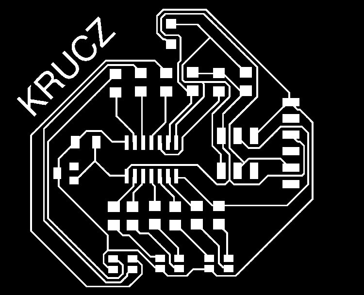
I churned out a design for a board which inclduded the hall effect sensor and the phototransistor. I also attatched 3 rbg LEDs so I would have something to make a simple indicator with. Below is the design for the traces and shape of board:
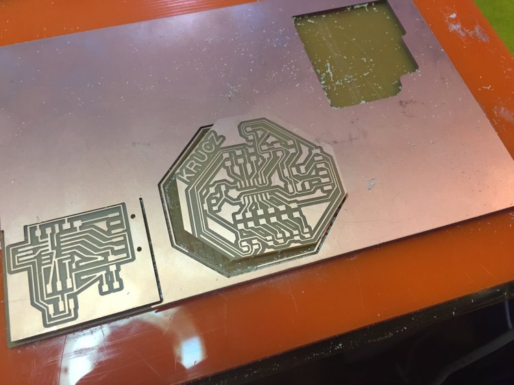
I ran these through the fab modules and made a silly mistake. I didnt make the design for the shape of the board a solid shape, it was just an outline. This meant that the modules cut two paths. One for the inside of the outline and one for the outside of it. The result of this was a trace being taken off the board which would have to be fixed either by cutting a new board or fixing it with a wire. For now the latter would be better as there could be more issues which may need to be rectified.
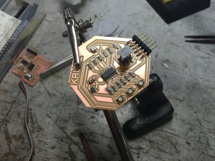
So I washed the board and went on to solder the board. This was the result:
After soldering I discovered another problem; the RGB LEDs were connected to the cathode instead of the anode. This would also be an issue. Now that the weekend is upon us, I will re-design the board over the weekend and next week work further on debugging the design.
12th April 2015 - Board re-design
Taking into account the issues I have found so far, I have re-designed the board and will get it milled and soldered. The revised design is below:
My next steps are to get the board made and look at programming it in C code (because that's what the pros use!).
I went through the design with one of our electronics gurus (Emma). She gave it the all clear so now it's time to go and mill the board! While I wait to do that though, I will look at the C programming.
I was able to get my second design milled out and soldered but there were quite a few unseen issues with it.
the first issue was that the reset pin wasn't wired up to the micro controller and instead an RBG LED pin was connected. I left out the connection between the hall effect sensor and the micro controller. Lastly the LEDs I used were the wrong ones for the design. This is a real mess so I will design a third version which will be much simpler.
13th April 2015 - Getting to know C code
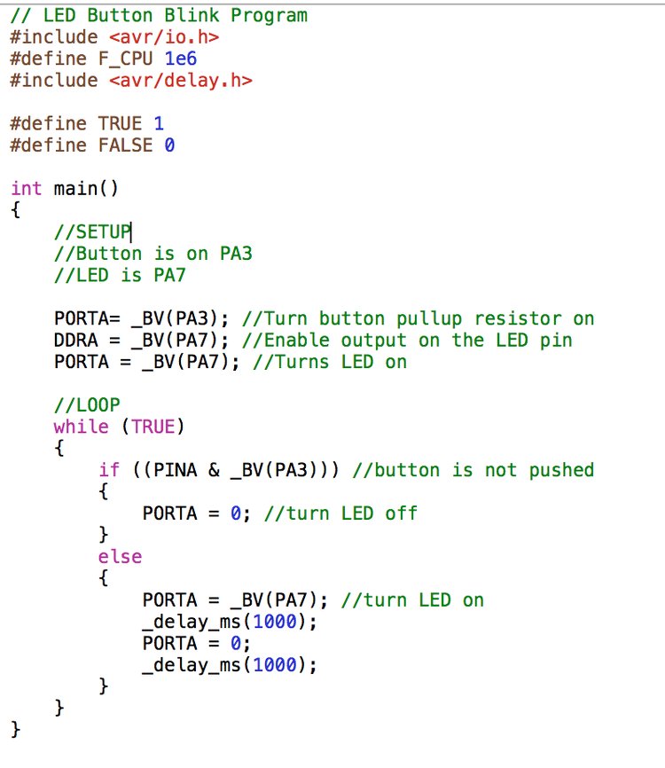
To start to get familiar with c-code I went back to the echo board and had a go at uploading the echo code using the tutorial that Neil provided. I managed to get it working and then found some C-code which would get the LED I added to blink with a few adjustments. The code is below:
Now that I had some of my own c code I just had to recall the steps to get it on the board. They are as follows:
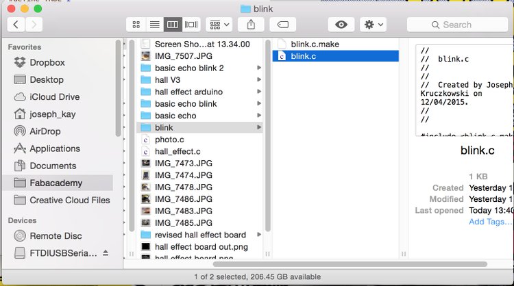
Make a folder with the name of the project (I called mine blink)
Inside that folder you need the c code file and the make file. They have the extensions .c and .c.make respectively. Take a look:
I used the make file Neil wrote. All I needed to change was the name of the file to match mine and in the code just replace the project name with the name of the c code file (minus the extension).
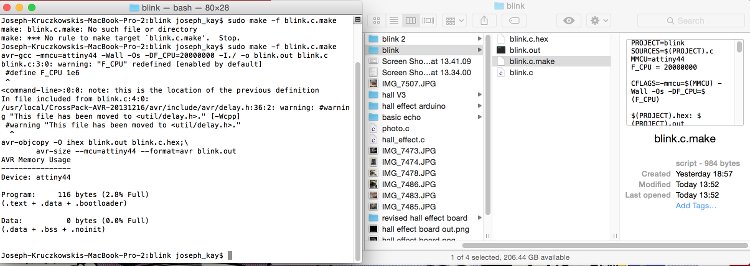
Now it is time to go to the terminal. With the ISP and circuit board correctly connected you need to tell the computer to use the .c.make file to convert the c code into something that the micro controller can use and put it on the board. To do this we type the following command:
The command used was "sudo make -f blink.c.make". You can see the two new files in the folder.
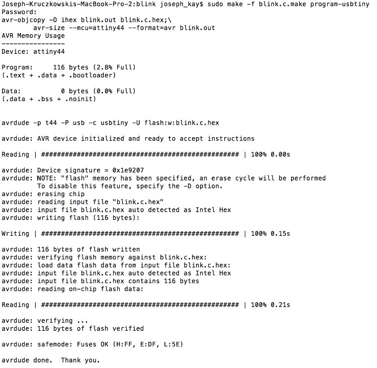
Now to put the code on the board you need to run the same command but also type "program-usbtiny" so the full command is "sudo make -f blink.c.make program-usbtiny"
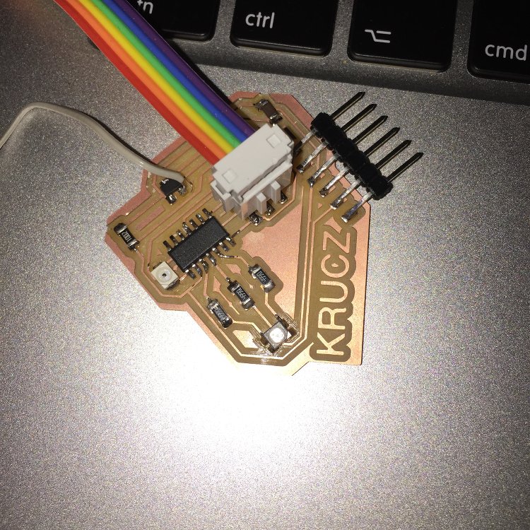
The final result:
Now that I know the procedure, it is time for me to make the third version of my board and adapt the c-code that Neil has written for the two inputs so that it works with the atiny-44 controller. Using the c code may be a bit abitious for me so i may resort to arduino if it gets tough.
I milled the third version of my board and got to work on recycling the components from the second board using a heat gun. In no time at all the board was soldered. To my annoyance I had failed to correct the issue about the hall effect sensor not being connected to a pin on the mocro controller so I focused on getting the phototransistor to work as time was ticking.
It was now time to get some code on the board. I started with arduino and burned the bootloader with the necesary settings. Next was to write some arduino code. I adapted an if statement template so that the RBG would light up in dark conditions. However, the code wasn't working. I asked Emma, one of the instructors for some help and it turns out that for the arduino to work correctly, it needs a much more accurate clock than the default one, or one with less of a percentage error. A way around this would have been to add an external 20MHZ clock but it was a bit late for that. I didn't add the clock because I intended to use c code which wouldn't have a problem with this. Thankfully there was a solution to the temporary issue in the for of another arduino program written by Zaerc, our coding guru. He wrote a fantastic bit of code which indicade the line of code required to make the clock accurate. The code is as follows:
Below is what shows in the serial montior when the code is run completely once. The lines starting with "OSCCAL" are the lines which have correctly calibrated the clock well enough for the serial communication to work and can then be used in other code. Zaerc said it is best to pick one from the centre of the pack. I picked "OSCCAL= 0x8B"
I then put that in my code so that it would now work (plus a few other tweaks). The code is as follows:
SoftwareSerial mySerial(7, 4);
// These constants won't change:constint analogPin = 5; // pin that the sensor is attached toconstint ledPin = 3; // pin that the LED is attached toconstint threshold = 400; // an arbitrary threshold level that's in the range of the analog inputvoidsetup() {
OSCCAL= 0x8B;
// initialize the LED pin as an output:pinMode(1, OUTPUT);
pinMode(2, OUTPUT);
pinMode(5, INPUT);
pinMode(3, OUTPUT); // initialize serial communications:
mySerial.begin(9600);
delay(1);
}
voidloop() {
// read the value of the potentiometer:int analogValue = analogRead(5);
// if the analog value is high enough, turn on the LED:if (analogValue > threshold) {
digitalWrite(3, LOW);
digitalWrite(2, LOW);
digitalWrite(1, LOW);
}
else {
digitalWrite(3, HIGH);
digitalWrite(2, HIGH);
digitalWrite(1, HIGH);
}
// print the analog value:
mySerial.println(analogValue);
delay(1); // delay in between reads for stability
}
You can see the code in action in this video and the serial communication:
You could say that I have completed the assignment for this week! Oh wait.. must not to forget the design files. However I really want to learn some more C code so there will be more documentation to come regarding that.