- Home
- My Assignments
- Project Management - Complete
- Computer Aided Design - Complete
- Computer Controlled Cutting - Complete
- Electronics Production - Complete
- 3D Scanning and Printing - Complete
- Electronics Design - Complete
- Embedded Programming - Complete
- Computer-controlled Machining - Complete
- Molding and Casting - Complete
- Input Devices - Complete
- Output Devices - Complete
- Composites - Complete
- Networking and Communications - Complete
- Interface and Application Programming - Complete
- Applications and Implications - Complete
- Mechanical and Machine Design - Complete
- Invention, Intellectual Property, and Income - Complete
- Final Project
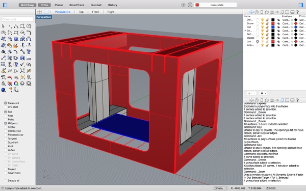
Building the stages
After a quick chat with the group, we all agreed on what to help out with. I decided to help build the stages with shirley. This began with preparing some cutsheets based on what was given to us already. After sourcing them, it was certain that the job will need to be don in two parts. First we decided to just slice the cut sheet into two and the rotate the cardboard half way:
We also did some test cuts so that the score lines and cut lines were just right:
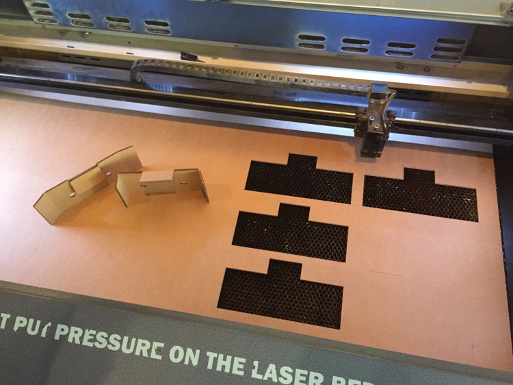
The ideal values were as follows:
Cutting: speed 2.7 power 100
Scoring: speed 10.0 power 100
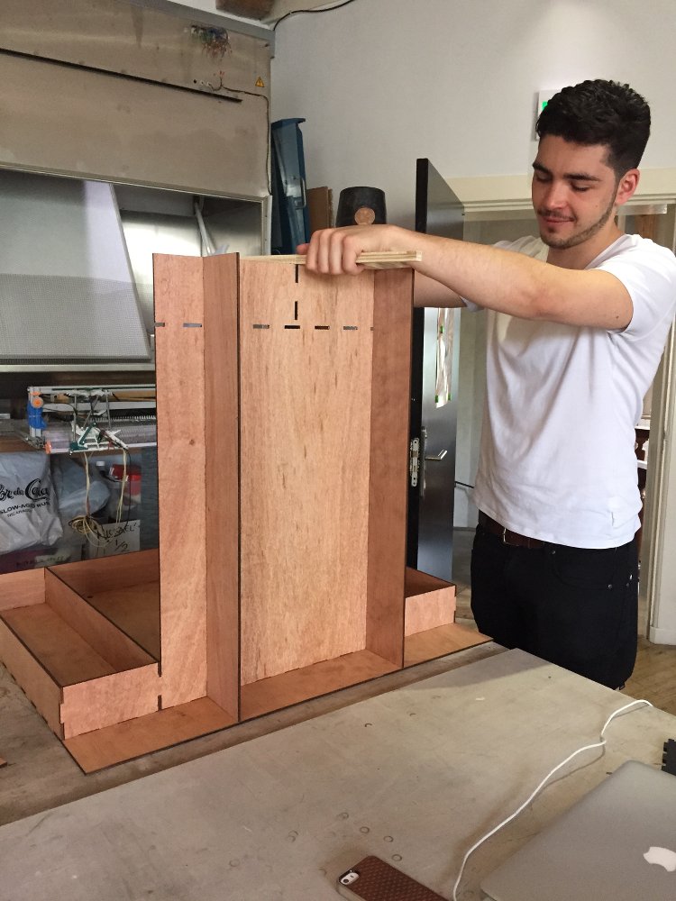
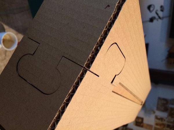
The first cut sheet turned out very inaccurate so we added a jigsaw style joint to the deisgn and made two cutsheets and tested it:
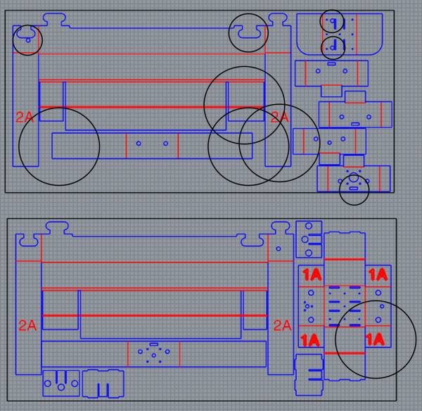
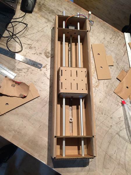
After making this stage, we noticed a seried of design flaws that needed altering. There were no holes for one stage to sit in another stage. We also added holes for end switches to sit in should we get the chance to add them. We also altered the space where the servo motor moves the end effector so that it will actually hit the endstop without falling out of place. Other issues included parts overlapping eachother.
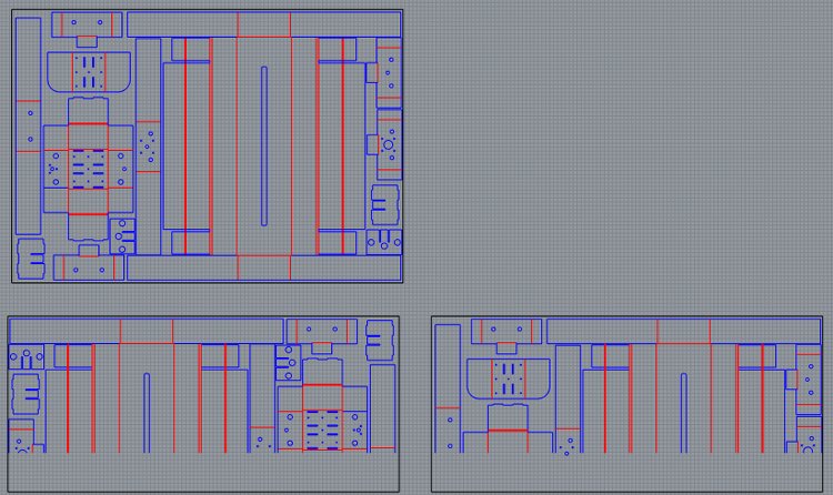
Here all the circled ares are where we made alterations:
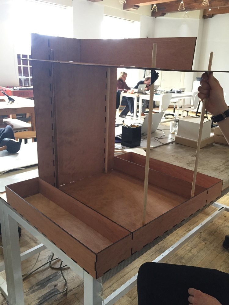
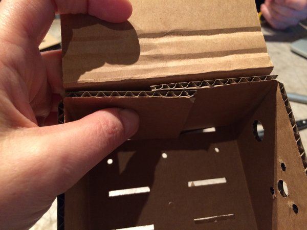
Here are the final stages:
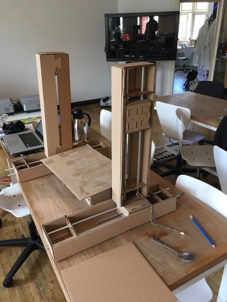
To glue them together we used 3M Photo Mount. A spray glue which was quick to work with.