Output Devices
For this week the intent was to use output devices
with the microcontroller platform that we have been
using. In previous assignments an LCD and 4 LEDs had
been used showing that the system was inded working
as expected. For this week we decided to add a servo
motor (MPI pico-servo), making it respond to an
input signal.
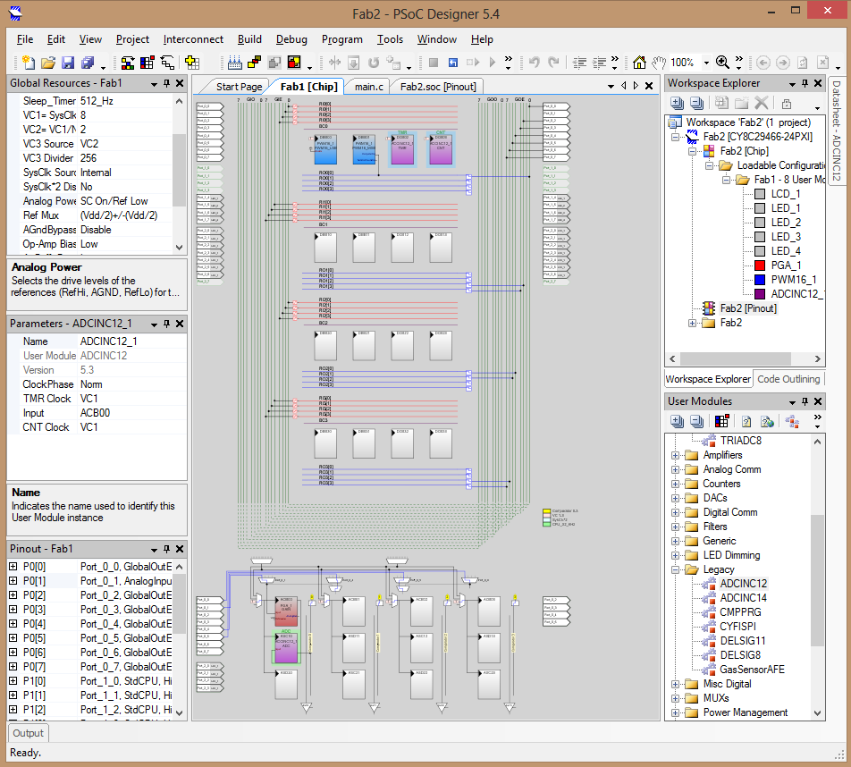
PSoC and a Servo Motor
Once again the micro-controller platform of choice was the PSoC in which the LCD and LEDs were already defined. Servo motors work with a closed loop control system that compares the position of the axis with a reference signal to achieve a given position. The reference signal is given as a pulsating signal with a fixed frequency (50Hz) but a varing width (PWM) ranging from 5 to 10% of the period. A PWM module was added to control the servo and can be seen in the figure below.
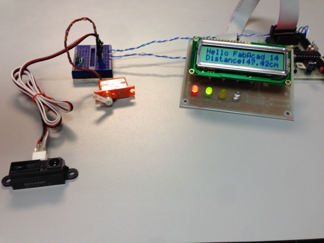
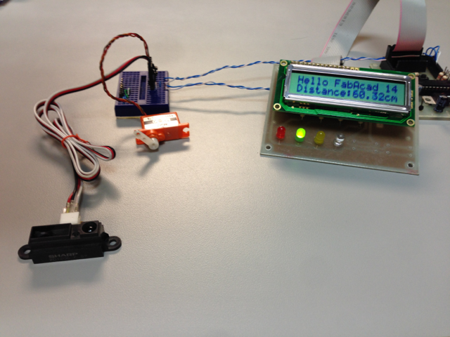
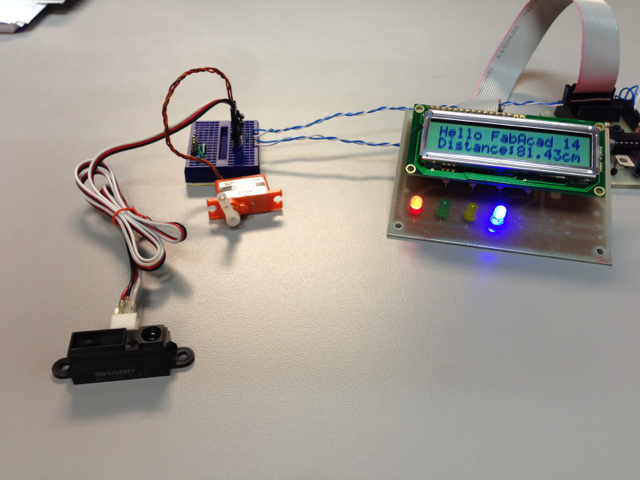
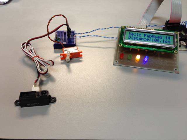
The C code from the input devices week was modified to provide an output to the servo that is proportional to the distance read from the infrared sensor. In this way, the servo would start horizontally and would rotate about 100 degrees as the infrared sensor reads a distance that ranges from 6 to 106 cm.
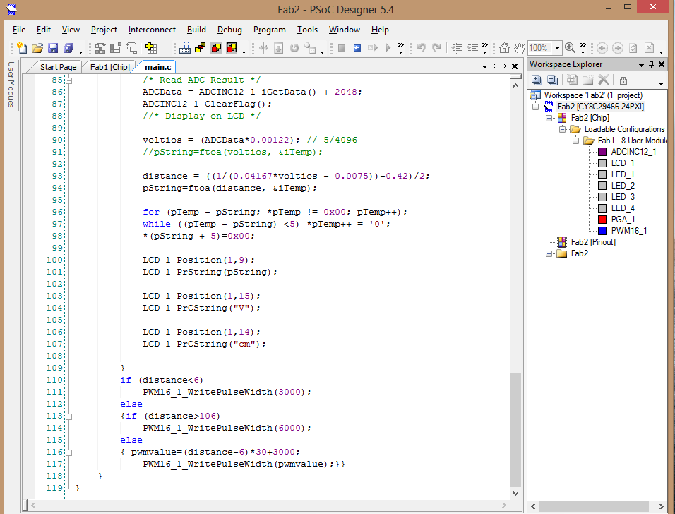
The processing of the data was simple multiplying
the distance by a factor of 30 and adding 3000 since
the range of motion of the servo was given in the
PWM between 3000 to 6000 time units corresponding to
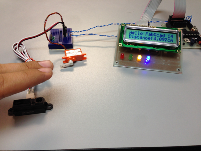
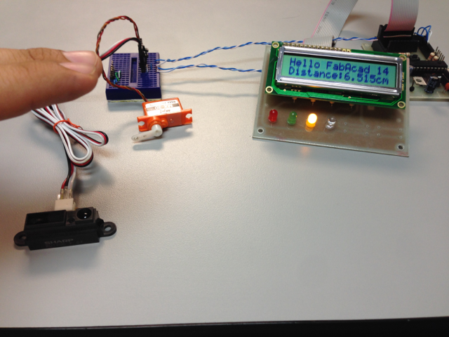
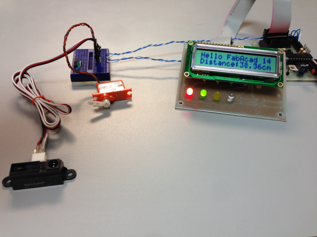
5 to 10% of the cycle. In the following figures you
can see how the attachment of the servo motor
changes the angle according to the distance sensed
in the range 6 to 106 cm.
Progress
- Project Proposal
- 2D and 3D Model
- Laser Cut
- Circuit Making - FabISP
- 3D Scanning and Printing
- Electronics design
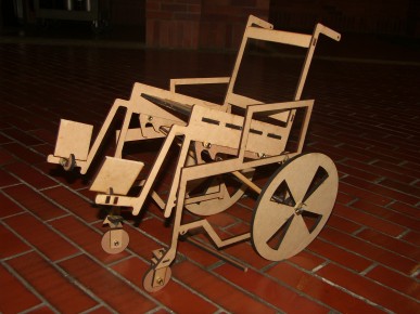
- Make Something Big
- Embedded Programming
- Molding and Casting
- Input Devices
- Composites
- Output Devices
- Networking
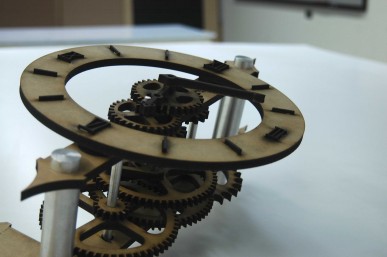
- Mechanical Design
- Interface
- Applications
- Invention
- Project Development
- Project Presentation
Alvaro J. Rojas Arciniegas, PhD
Assistant Professor Department of Automatics and Electronics - UAO
+57 (2) 318-8000 ext. 11384
