Final Project
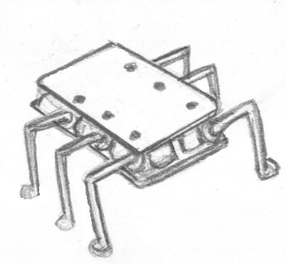
As it was reported in the mechanical design
assignment, the final project has switched to a
hexapod robot. The intent of the robot is to be able
to walk through various terrains or surfaces by having
six legs, each one with two degrees of freedom: one to
move it up or down, and one to move it forward or
backwards.
Actuators and sensors selected
The first selection was the type of actuator to
use. Multiple alternatives were considered but
looking for ease of driving and compactness the
pico-servos were selected. Driving them with a micro
controller was shown in the output devices homework
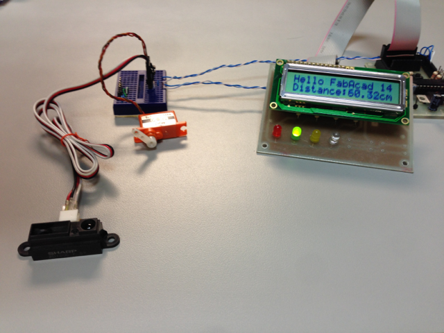
(see image below). Similarly it was important to
select some way to sense the environment in order to
facilitate navigation. Infrared sensors were
selected based on the range they covered (10-80 cm)
and the direct output of 0-5V making it easy to
interface with a micro controller. One was also
tested in the input devices and output devices
homework (see image below).
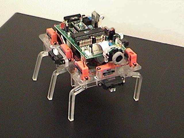
First Attempt
The first attempt achieved the simplicity and
compactness but the motors were inadequate for the
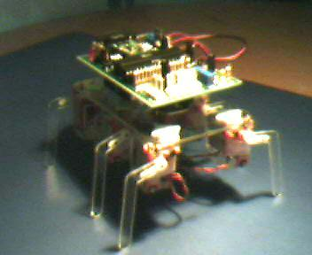
load that the robot required. All the pieces that
made the body of the hexapod, the legs, and the
structure to connect two servos in place were made
in acrylic cut with the laser cutter. A photo of the
early design can be seen below next to the model in
Solid works. The main flaw was not to consider the
weight of batteries which ended up being
significant.
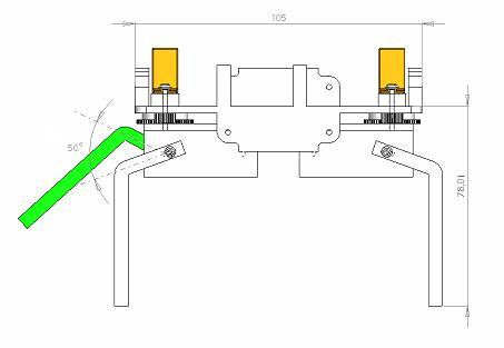
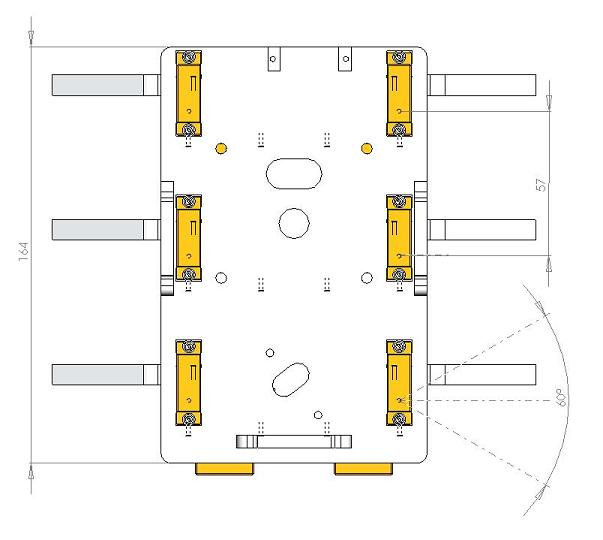
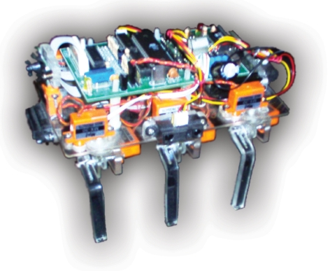
Second Attempt
Despite having a fairly simple and compact design,
the motors had a lot of problems maintaining the
standing position, and it was noted that most of the
range of motion of each servo was being wasted
because each articulation of the leg did not move
the 180 degrees which is roughly the range of motion
of the servo. Gears were used to provide more force
in each leg while maintaining an acceptable range of
motion.
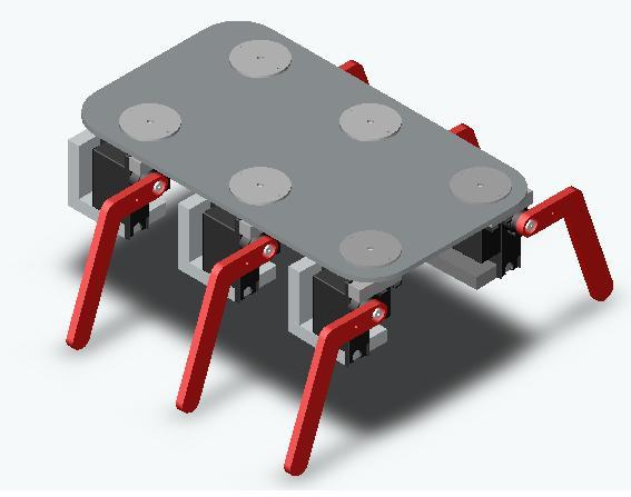
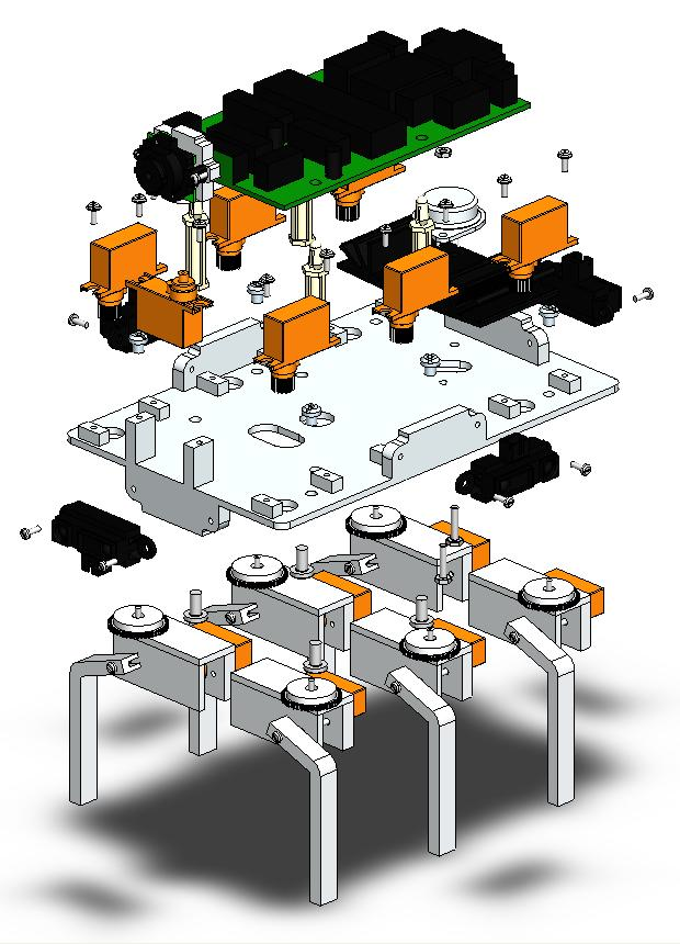
This new version was done similarly, in acrylic cut
with the laser cutter, small pieces to mount the
sensors were cut separately and glued into the base
with crazy-glue. An exploded view of the final
assembly can be seen below.
Electronics Design
Part of the intent of the electronics was to have a
single board as compact as possible. Single layer
designs resulted in too many bridges and connections
so a 2 layer design was done which allowed for a
much compact PCB. The design of the board was made
and then it was sent to a local shop that had more
experience with multiple layer PCBs.
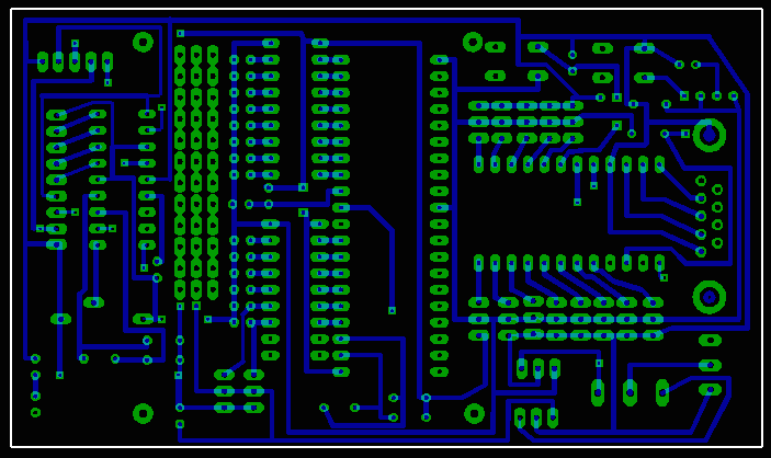
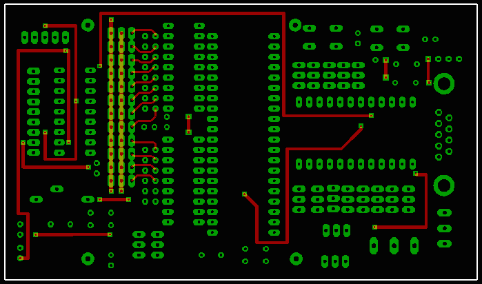
As you may notice in the printout of the board the design was made jointly with my friend Fabian A. Salazar who is not participating of the FabAcademy.
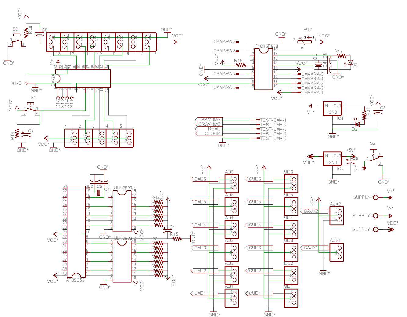
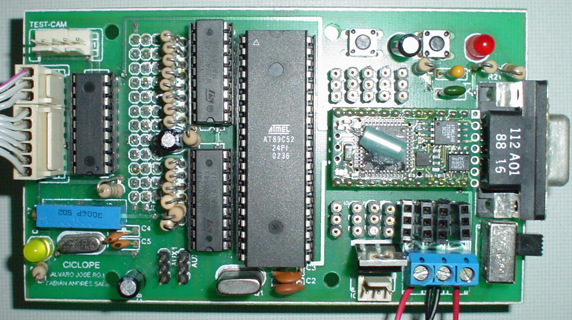
To control the movement of the legs there is a
master microcontroller basic stamp BX-24 that is
programmed in basic and an Atmel AT89C52 that was
programmed in assembler to generate the PWM for the
servos. The two microcontrollers are connected
through serial communication in which the master
indicates which step to take: forward, backwards,
turn left, or turn right, and the slave does the
generation of PWMs to produce the step.
Progress
- Project Proposal
- 2D and 3D Model
- Laser Cut
- Circuit Making - FabISP
- 3D Scanning and Printing
- Electronics design
- Make Something Big
- Embedded Programming
- Molding and Casting
- Input Devices
- Composites
- Output Devices
- Networking
- Mechanical Design
- Interface
- Applications
- Invention
- Project Development
- Project Presentation
Alvaro J. Rojas Arciniegas, PhD
Assistant Professor Department of Automatics and Electronics - UAO
+57 (2) 318-8000 ext. 11384
