Input Devices
For this week the intent was to read a signal from
a sensor or input device using a microcontroller
platform. In a previous assignment the PSoC platform
had been used so we decided to use this once again.
The input device selected was first a simple
potentiometer (10K Ohms) set up as a linear slider
and later the infrared distance sensor GP2D12 from
Sharp. The datasheet can be found in www.sharpsma.com.
PSoC and the Linear Slider
The PSoC platform has the advantage of including
analog configurable hardware blocks that can be used
as analog-to-digital converters (ADC) that are very
useful in reading an analog signal from one of its
pins.
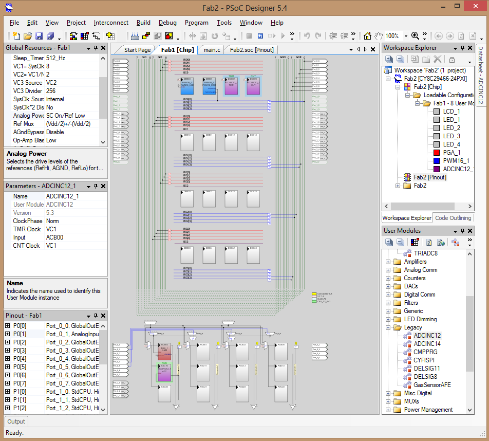
Although the programming environment is based on C
and includes a wiring interface in which you drag
and drop predefined modules it was necessary to
configure the input pin as an analog input, set the
clock signal for the conversion rate of the ADC, set
a gain block that act as a buffer to have better
impedance at the entrance of the signal and have a
cleaner signal. All those configurations were done
in the PSoC Designer interface with the guidance of
professor John Jairo Cabrera here at UAO.
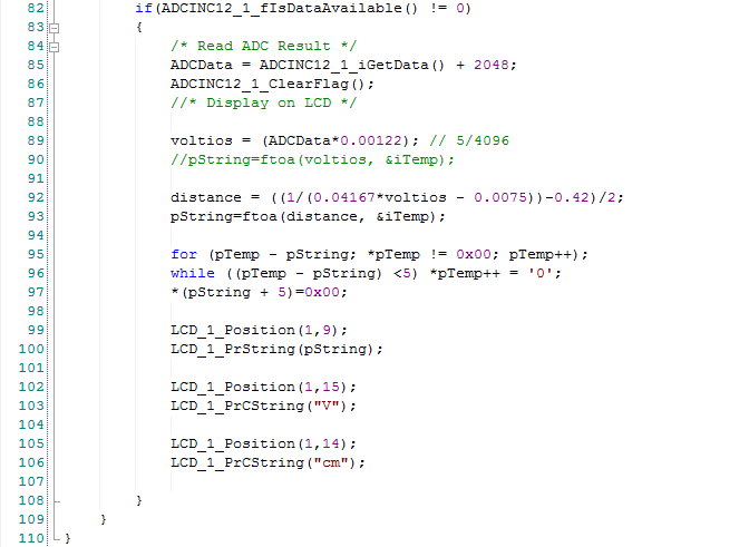
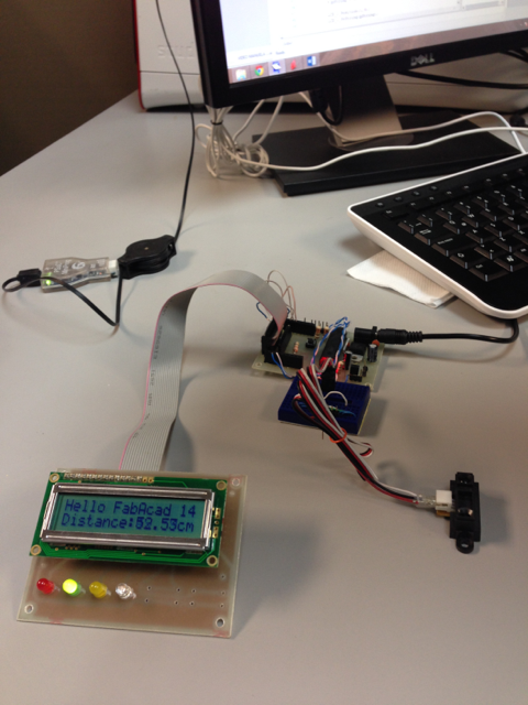
The C code is fairly simple, it consists of declaring variables to store the reading (ADCData) and converting it into a floating value representative of the voltage (voltios) of the signal and later the distance according to the sensor. The floating value requires conversion into a string to be able to output the value in the LCD.
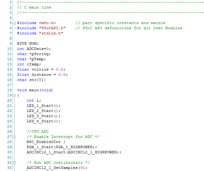
Part of the processing necessary to display the
value is first to understand the equivalent of the
reported value, in this case the ADC has 12-bits and
the entire range cover signals from 0-5V, therefore
the convertion to volts implies multiplying by 5 and
dividing by 4096 which corresponds to the scaling
factor 0.00122. This was tested with the
potentiometer / linear slider.
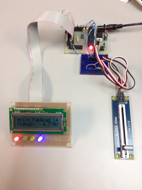
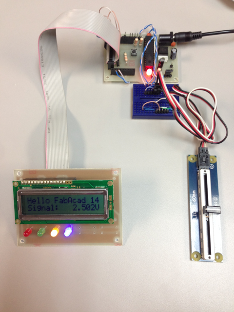
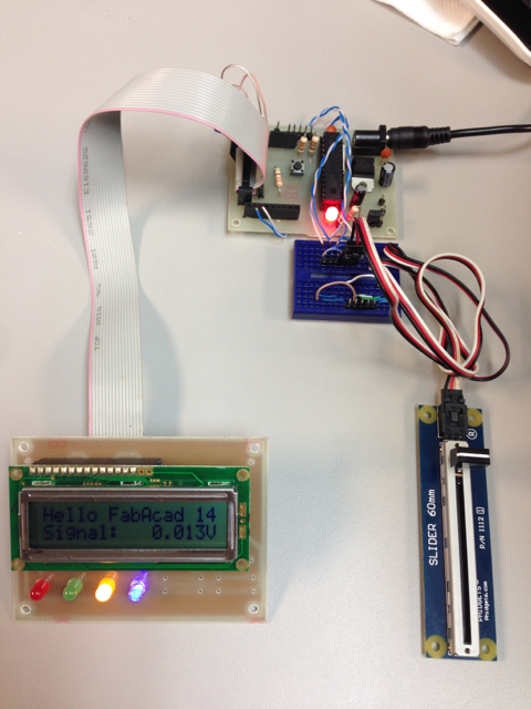
The LEDs underneath the LCD blink according to the
routine defined in a previous homework. Notice also
the value reported with respect to the position of
the slider.
Infrared Distance Sensor
Once the data was being displayed correctly on the
LCD, the work was to correlate that electric signal
with the distance of the object. According to the
datasheet referenced before, the sensor responds
aproximately linear to the inverse of the distance
(iD) in a range from 9-80 cm. The equation extracted
from the graph was iD=0.04167*V-0.0075, and then
distance L=(1/iD)-0.42. This was coded in the
program but the system return double the distance, a
factor of 2 was incorporated and the system
performed as expected.
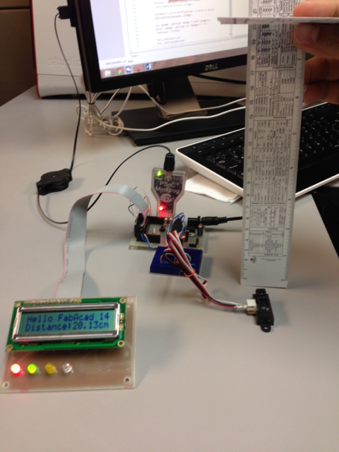
Notice the distance on the ruler corresponds with
the distance on the LCD.
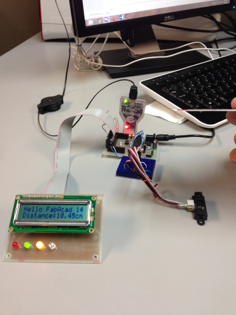
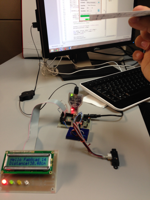
The PSoC board allows to be disconected from the
programmer to work as standalone which is also shown
below.
Progress
- Project Proposal
- 2D and 3D Model
- Laser Cut
- Circuit Making - FabISP
- 3D Scanning and Printing
- Electronics design
- Make Something Big
- Embedded Programming
- Molding and Casting
- Input Devices
- Composites
- Output Devices
- Networking
- Mechanical Design
- Interface
- Applications
- Invention
- Project Development
- Project Presentation
Alvaro J. Rojas Arciniegas, PhD
Assistant Professor Department of Automatics and Electronics - UAO
+57 (2) 318-8000 ext. 11384


