15. Mechanical & Machine Design
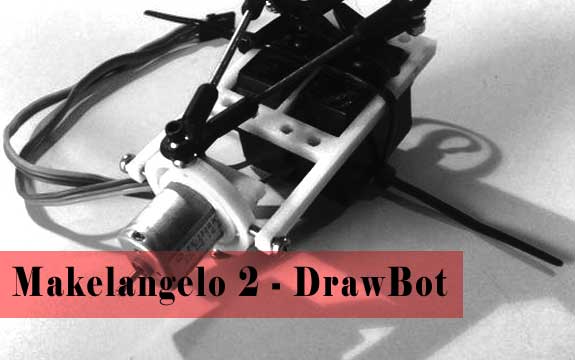
This week we are building the Makelangelo 2 DrawBot. Each facacademy student will take on a a specific part of the project. I will be working on the Stepper Shield.
Adafruit Stepper Motor Shield (Self-Fabbed)
Locating / Downloading the files
Adafruit has made the Schematic and board files available to download at http://adafruit.com/products/81#Downloads.
Converting Schematic/ Board Files to PNG
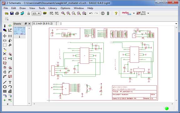
The above image is the schematic that I downloaded from Adafruit's website.
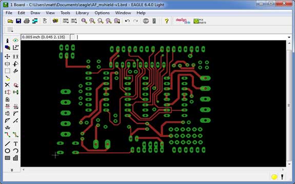
The image above is of the board with all layers turned off, besides the ones that will be milled (I will need 3 files for milling). I then saved the three boards using monochrome and a dpi of 500. The last step is to flip the last file (the bottom file) in photo editing software.
Finalized PNG Files
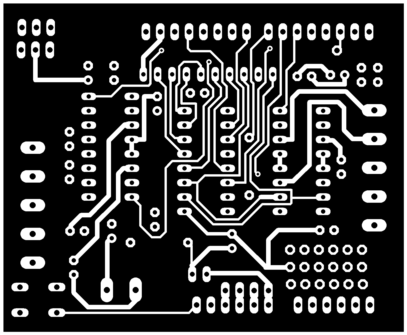
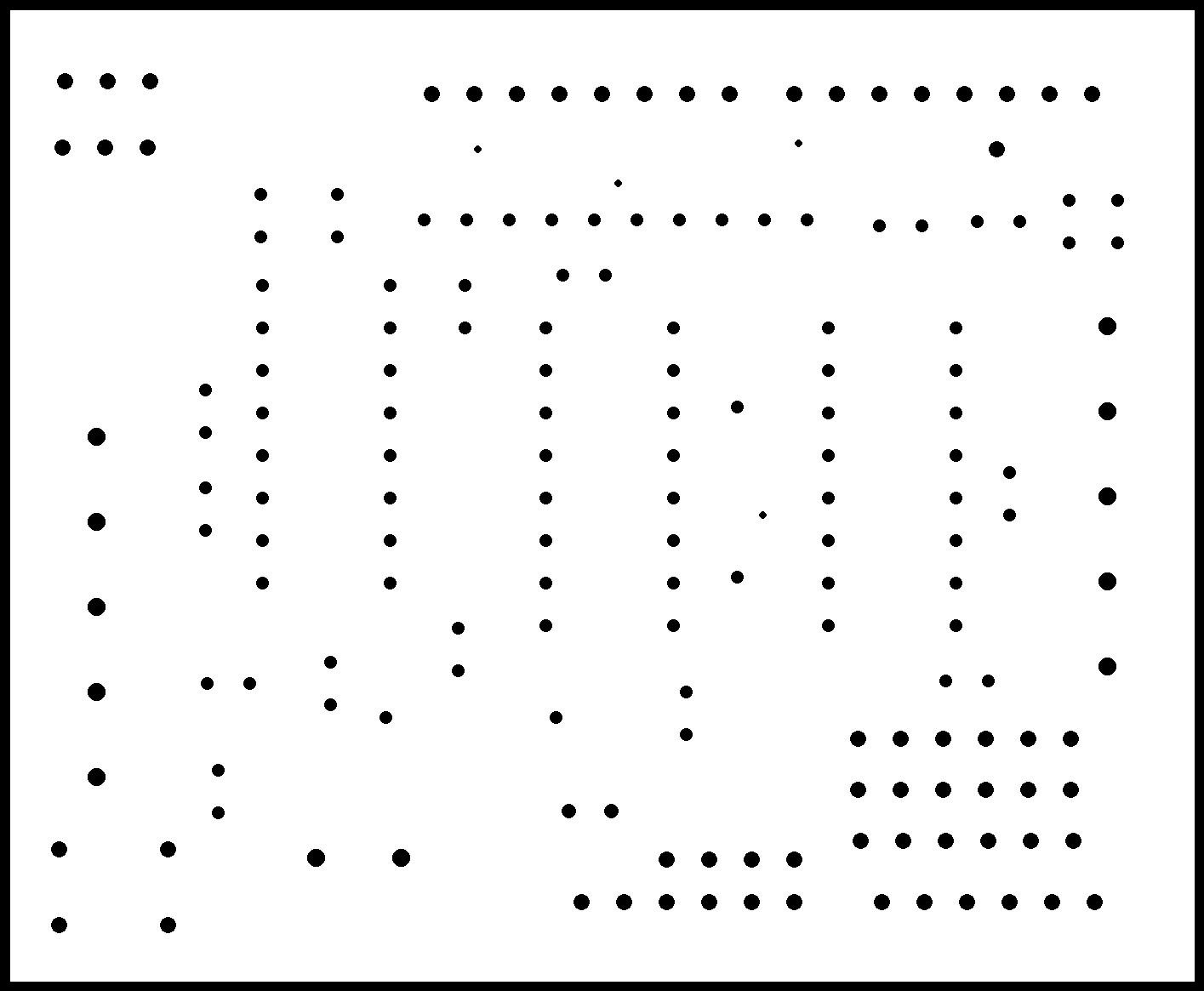
The top of the board, ready to be milled (right click, save as). This file will be milled out first.
The next file that will be milled are the through-hole parts. This will also cut the board out allowing us to flip it so that we can mill the bottom (shown in the diagram below).
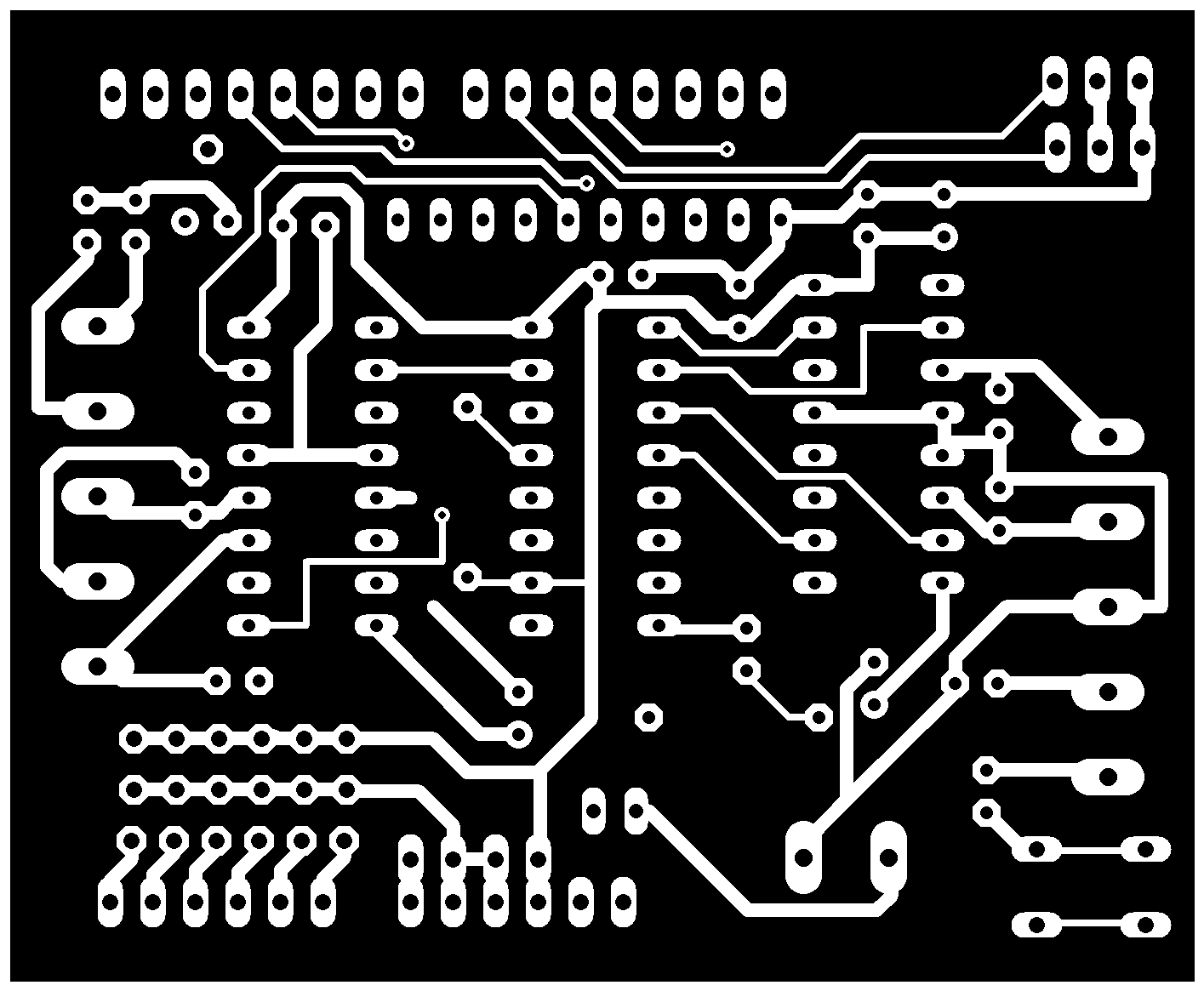
The third and final file is where it gets tricky. This needs to be aligned very well so that the top traces and through-holes are in the same spot. It can allow for some margin or error, but it is minimal.
Milling the Board
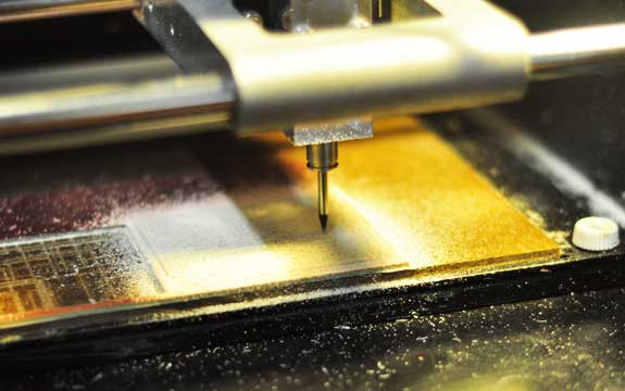
Milling the first PNG (the top traces) is straight forward and done the same way as usual. The same for the interior traces (that mill out the through holes and outline).
The next step is slightly more complicated, where I took the top milled board, stuck double sided tape to it flipped the board over so that the top is facing down. The next step will be to mill the bottom traces.
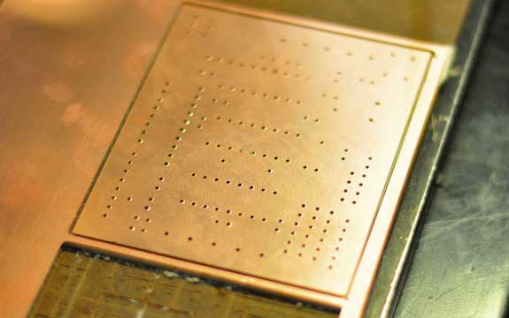
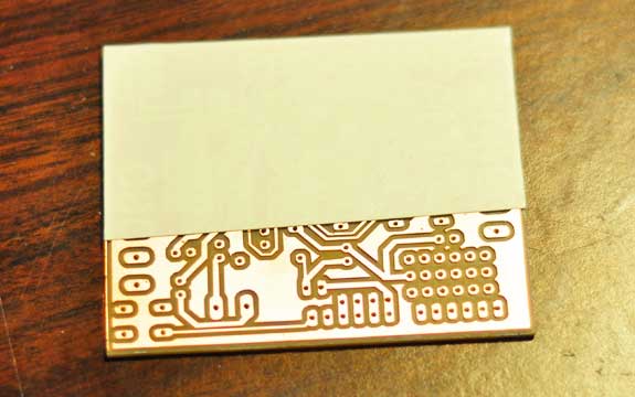
Above, the flipped board is shown. The complicated part is to align it perfectly so that the traces will mill properly. It took a couple attempts before I felt confident it would come in close range to the already milled holes (you can see that this was the second attempt, the first did not align perfectly, leaving a few errors on the finished milled board).
The final milled board shown above. In the light you can see that the board is a double sided board and it aligns almost exactly.
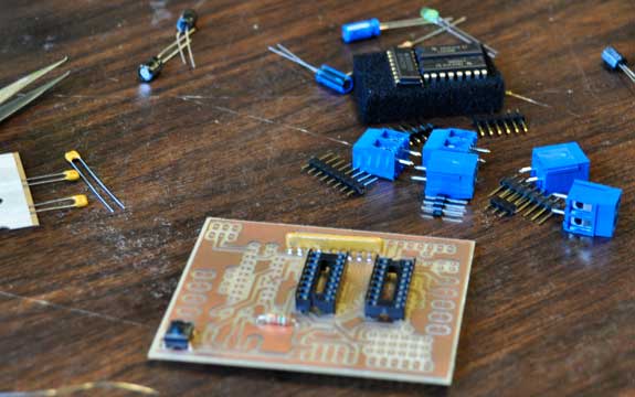
Adding Components
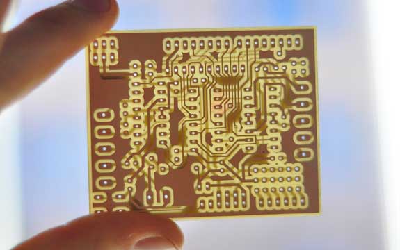
Now that I have a clean and hopefully functional pcb, the next step is to fill it with components. The components have been ordered from adafruit and are the same as the store bought version. (or so I thought!!)
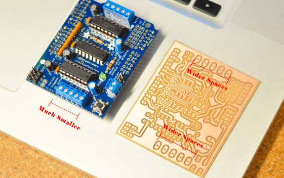
It turns out there are a few differences between the bought board and the files they have provided. First of all the spaces between the terminal blocks are much wider (3.5mm vs 5mm for the fabbed board).
The fabricated board is the one shown above (I am assuming that it is a slightly older version). It has a few minor differences so we will have to fully test the sizes. This image was found at http://www.elecfreaks.com/store/arduino-motorstepperservo-shield-p-475.html
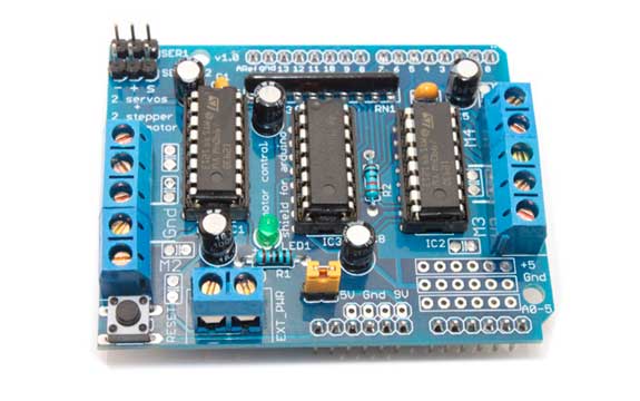
I used the components of the newer version on the older board (which is basically the exact same).
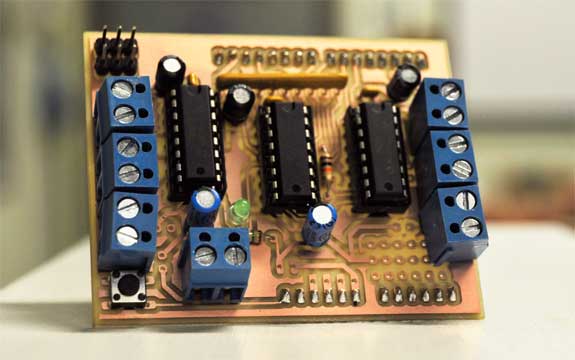
The completed board. Ready to be used in the following test in combination with the Drawbot.
Testing it on the Makelangelo 2 Drawbot
Working DrawBot!!

