13. Output Devices
Jump to: LED Array
LED Array
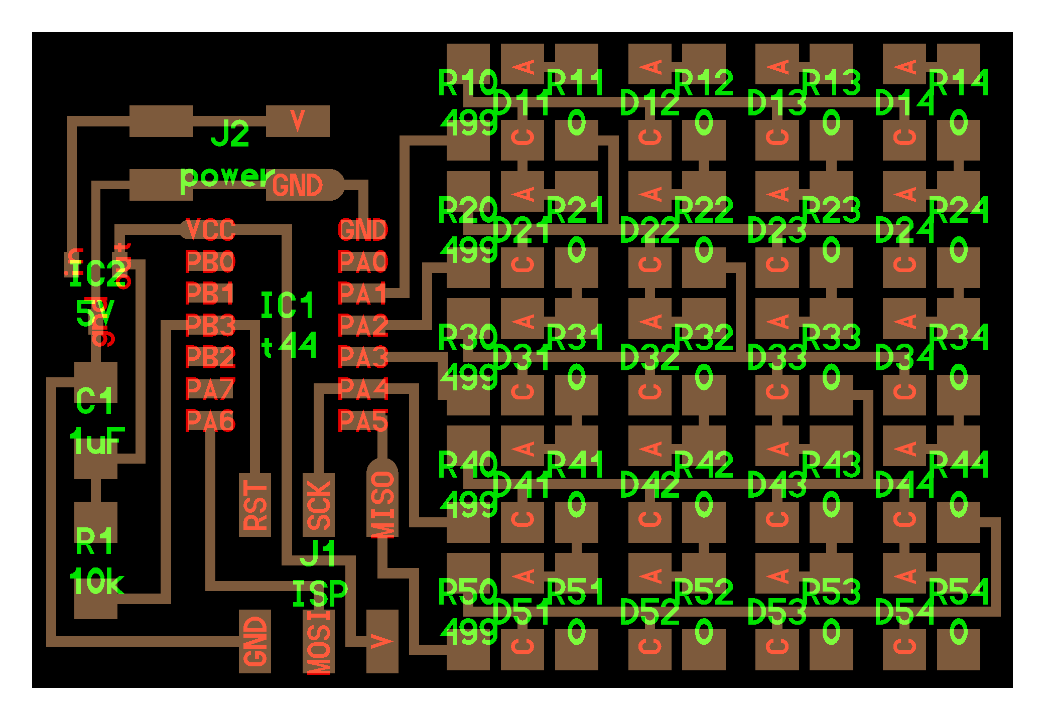
The image above shows the board with its components
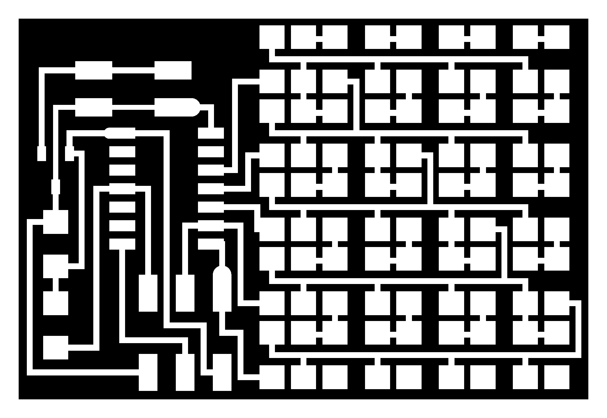
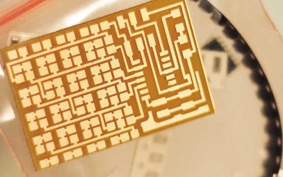
The traces that needed to be milled out on the Roland Modela
The first board I made was the LED Array board.
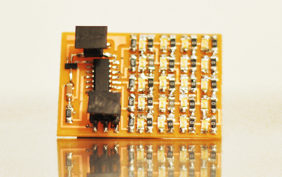
The image above shows the final completed board, several hours went into the making of it! It was extremely easy to miss a connection or worse, reverse an LED.
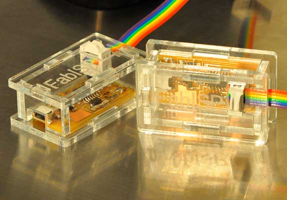
The next step is to download the Make file from the MIT website and flash it to the board with the help of the earlier created FabISP (shown above in its custom enclosure).
If the code is installed correctly it should say:
avr-objcopy -j .text -O ihex hello.array.44.out hello.array.44.c.hex;\
avr-size --mcu=attiny44 --format=avr hello.array.44.out
AVR Memory Usage
----------------
Device: attiny44Program: 358 bytes (4.4% Full)
Data: 1 bytes (0.2% Full)
(.text + .data + .bootloader)
(.data + .bss + .noinit)avrdude: AVR device initialized and ready to accept instructions
avrdude -p t44 -P usb -c usbtiny -U flash:w:hello.array.44.c.hexReading | ################################################## | 100% 0.01s
avrdude: Device signature = 0x1e930c
avrdude: NOTE: FLASH memory has been specified, an erase cycle will be performed
To disable this feature, specify the -D option.
avrdude: erasing chip
avrdude: reading input file "hello.array.44.c.hex"
avrdude: input file hello.array.44.c.hex auto detected as Intel Hex
avrdude: writing flash (358 bytes):Writing | ################################################## | 100% 1.08s
avrdude: 358 bytes of flash written
Reading | ################################################## | 100% 0.68s
avrdude: verifying flash memory against hello.array.44.c.hex:
avrdude: load data flash data from input file hello.array.44.c.hex:
avrdude: input file hello.array.44.c.hex auto detected as Intel Hex
avrdude: input file hello.array.44.c.hex contains 358 bytes
avrdude: reading on-chip flash data:avrdude: verifying ...
avrdude: 358 bytes of flash verifiedavrdude: safemode: Fuses OK
avrdude done. Thank you.
Success!!! Now its time to start playing with the board!
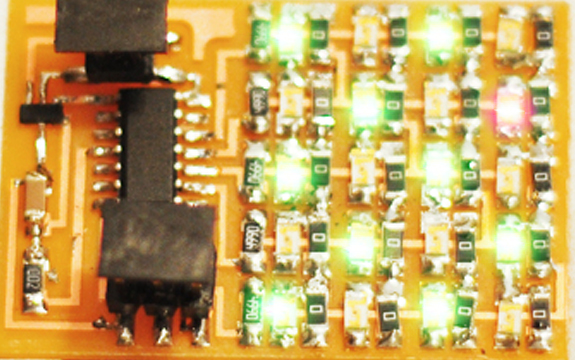
The image above shows the working board, with one random stray red LED. Since they all look the same it was hard to tell what color it was, but 1/20 is not a bad job.

