04. Electronics Production
This week's assignment is to make the FabISP. To do this we will need to download the files for the board, mill the board, solder several components to it and finally program it for use with our custom PCBs. We will be using these programmers throughout the semester to program the other boards we will create.
Downloading the files
This week we will be working with an existing design / schematic diagram of a small PCB called the FabISP (shown below). The files were downloaded from MIT's server.


The images above are the files we need to download in order to make the boards. Left is the actual board that we need and will be milled using a 1/64 bit. The image in the middle is the outline that will be milled to separate the board from the copper sheet, this will be milled with a 1/32 bit. And the image on the right is the schematics for the pcb showing which components will be placed where.
Setting Up the Files
There are a few steps we need to do in order to mill the pcb.
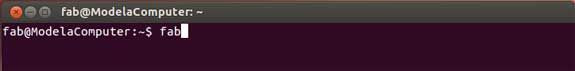
To set up the files we open up terminal and type in 'fab' which brings us to the fab modules panel.
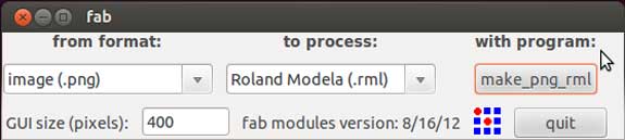
Next we need to select a format and a process from the fab modules interface. The format we need to select is .png (as this is the file we downloaded earlier), the process is Roland Modela .rml and using the program make_png_rml.
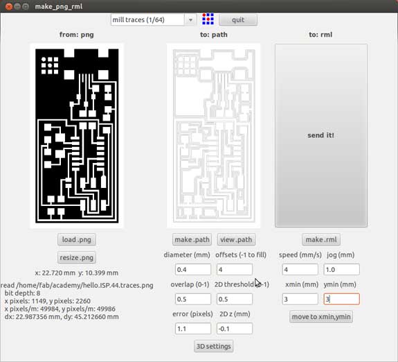
This brings us to the make_png_rml interface where we can select the actual png we downloaded earlier and make a path. The image above shows the png in black and white. The black part is what will be milled away and the white is what will be left over, the copper coating.
Milling The Board
Using the Roland MDX-20
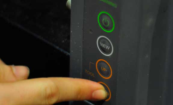
Its important to turn the machine off and on when changing a tool. View is used to reset the spindle's location and the up / down buttons are there to mive the spindle on the z axis. When moving down it is important to move it slowly (or pulse) when coming close to the boad.
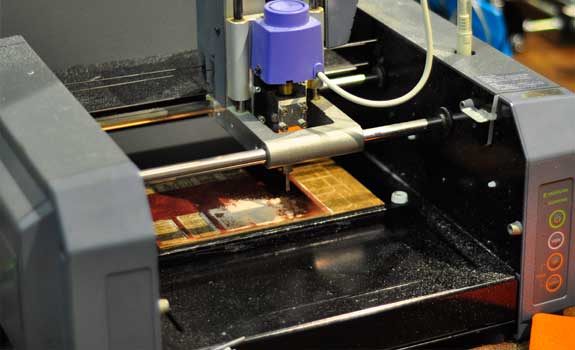
The Roland MDX-20 at work. Taking approximately 7 minutes to mill the board and an extra few minutes to change the tool, set up the exterior file and to mill away the boundry.
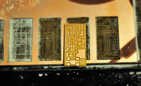
The image above shows the completed board milled out of the larger copper sheet. When using it precise we can get approximately 12 boards out of a single sheet.
The components necessary to make the ISP
- 1 x ATTiny 44 micro-controller
- 1 x Capacitor 1uF
- 2 x Capacitor 10 pF
- 2 x Resistor 100 ohm
- 1 x Resistor 499 ohm
- 1 x Resistor 1K ohm
- 1 x Resistor 10K
- 1 x 6 pin head
- 1 x USB connector
- 2 x jumpers - 0 ohm resistors
- 1 x Cystal 20MHz
- 2 x Zener Diode 3.3 V
- 1 x usb mini cable
- 1 x ribbon cable
- 2 x 6 pin connectors
Assembling the board and components
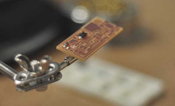
The following image shows the first components soldered to the board as a final product.
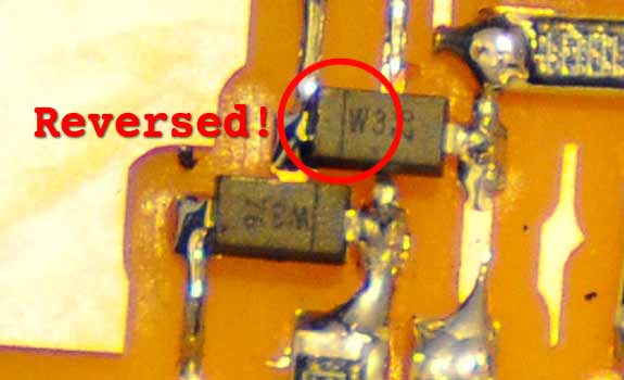
Problems - The problems I encountered with soldering the board were few but very frustrating and time consuming to figure out! In the end it was discovered that one of the diodes was placed incorrectly. There is a tiny barely visible line on that should be aligne on the right side of the part. In my case, as I was focussed on soldering this increadibly small component to the board, completely overlooked the fact that I had to check its orientation.
Install the Necessary Software for AVR Programming
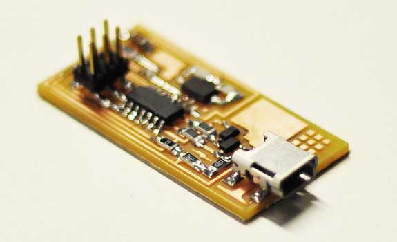
We are using an Atmel AVR to flash code to our newly created FabISP. The board I created survived the 'Smoke Test' and has a green light on the AVR. The next step is to download software in order to get "avrdude" and "GCC" - this is done via Crosspack AVR and Xcode (on Mac). We also need to download and unzip the firmware from MIT's server.
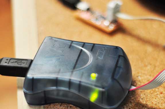
The image above shows the first 'power on' and green light for the FabISP. This means there were no errors, everything connects correctly and we can proceed to programming the board.
Programming the Board
The next step is to program the board. For this I went into Terminal on Mac and followed the steps provided in the tutorial.
- 'make clean'
- 'make hex'
- 'sudo make fuse'
- 'sudo make program'
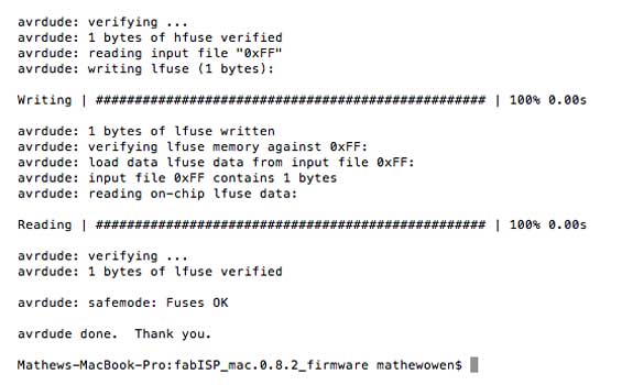
Once this is completed (without errors) the board is programmed and ready to use. We still want to verify that the ISP is working correctly. The final message should read "Your FabISP device has been successfully programmed and is recognized by your computer".
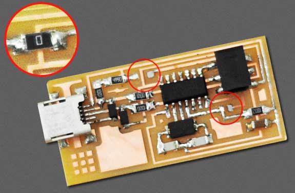
Removing the 0 ohms Resistor
The final step was to remove the 0 ohms resistor in order to use the board as an ISP. The 0 ohms resistor was only necessary for programming the board, in order to use it it has to be removed.
The custom FabISP enclosure (downloadable)
As a final extra added step was to designed and laser cut a custom enclosure for the FabISP (shown below) to keep it safe and from dust, water, etc and at the same time make it look more like a final product.
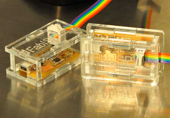
The FabISP in the acrylic enclosure, a snug press-fit connection. It also holds the FabISP firmly in place within the enclosure, so no glue or other adhesive is necessary. I designed it with a small pertruding top and bottom so that it can be opened and clicked back together without the acrylic cracking.
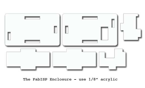
I have included a file for anyone interested in using it on their FabISP. The enclosure was cut from 1/8" clear acrylic. You will need to rescale the width of the holes when using metric sized acrylic (such as 3 mm acrylic). Also note that the milled board may need some sanding, depending on milling settings, mill and precision of tool used. Click the link to download the drawings for the FabISP Enclosure v2.

