02. Computer Aided Design
Jump to: 2D CAD Design | 3D CAD Modeling
2D CAD Design
Inkscape
Inkscape ia a user friendly free vector graphics software that we will be using a lot during this course as a tool for creating drawings to send to the vinyl cutter.
The design I created was just a test to try different methods to quickly learn the basics of Inkscape. I made it by simply using random components of bitmap drawings and photos along with additional drawing directly in Inkscape. The reason for doing this was to test the different possibilities of Inkscape such as the bitmap tracing capabilities. In addition the design used various sizes and detail to test the capabilities of the vinyl cutter and to see how accurate smaller detail could be cut compared to larger straighter portions.
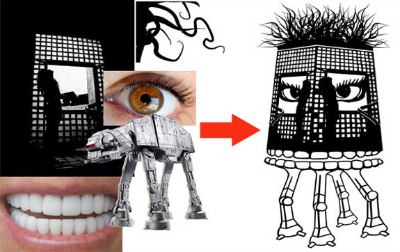
The finalized image was the exported as a .png and imported into Inkscape. In Inkscape the document size was altered (File -> Document Properties [or Shft+Ctrl+D] -> Set width according to vinyl width and height according to imported image). The image was the imported using File -> Import -> 'image name'.
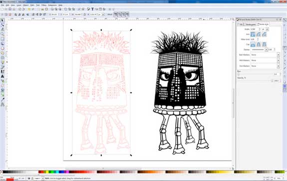
The next step was to trace the imported image by clicking on Path -> Trace Bitmap [or Shift+Alt+B] -> Adjust settings and click OK. The original (bitmap) image can be discarded and we are left with a vector image that closely resembles the original image. From that image (shown in black above) needs to be turned into paths in order to be able to (shown in red above). We do this by clicking on Object -> Fill and Stroke [or Shift+Ctrl+F] -> then in the dialog box turn off the fill by selecting the X, turn stroke paint on and give it a color of 255 (red). The vinyl cutter needs a path to be able to cut properly and the path needs to be displayed in red. The last step is to give the stokes a width of 0.5 points.
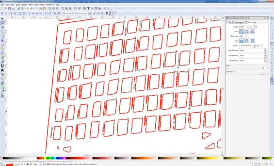
Before sending it to the vinyl cutter I refined the image and removed all the small extra vectors that might cause any problems for the cutter. The 'Edit paths by nodes' tool was used in removing all unnecessary parts (shown above).
Corel Draw
Corel Draw - a low cost vector graphics editing software that works great in conjunction with both the vinyl cutter and the laser cutter. We wll use corel draw during this this program to send files to the laser cutter. We will however use Inkscape more frequently as it is a free software package that can perform most tasks we will be dealing with during the course.
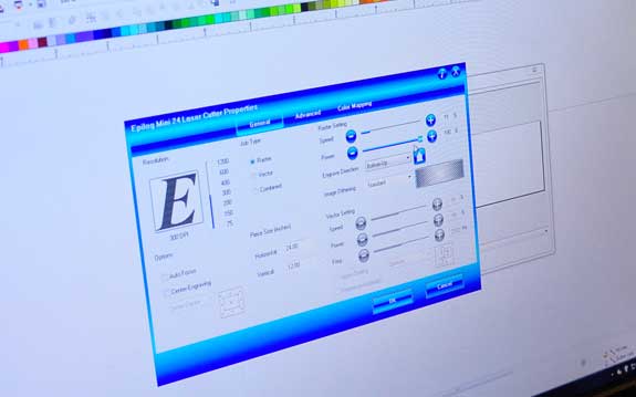
The image above shows the use of Corel Draw in combination with the laser cutter. As I do not have Corel Draw installed on my computer I will be limited to working with it only in conjunction with the laser cutter.
Illutrator
Adobe Illustrator - an upgrade to Inkscape in that it is far more diverse. Free versions are available for non-commercial work. However, as Inkscape has most components necessary for the course of the Fab Academy we will not focus on it too much.
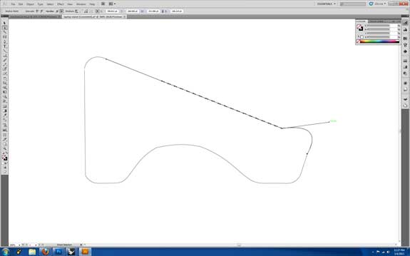
Using Adobe Illustrator I created a 2D drawing that I will later use to model a laptop stand that I am planning to laser cut for next week's project. Using the pen and line tools I drew a base shape as a sectional view for the stand.
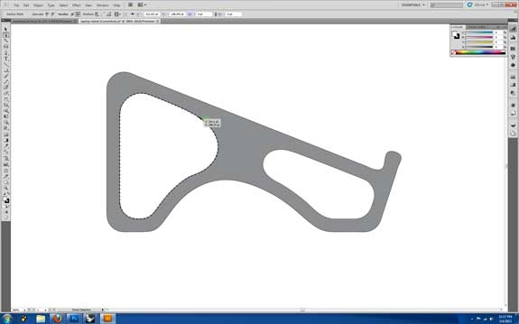
Once I was satisfied with the final shape I exported the drawing as a .dwg which I will be able to open up in Rhino 3D.
3D CAD Modeling
Rhino 3D
Rhino 3D is a great 3D modeling software package for NURBS modeling. What makes Rhino an even more powerful tool is that it has several free plugins, like the very popular Grasshopper. I will use Rhino in conjunction with Grasshopper for the final project as it is an extremely powerful tool in digital fabrication.
Modeling a 'Waffle Structure' Laptop Stand
Click here to download the file for the rhino model. The fabricated parts were accidentally deleted and will have to be recreated. I will upload this file again soon with full fabrication sections for anyone else who might want to use it for their laptops. Untill that time I have shown my workflow how I modeled the stand.
The first step was to import the file I created in Illustrator into Rhino, copy it and scale the middle section so that the form becomes slightly more interesting.
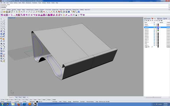
I then created a surface from the exterior curves which will serve as the main structural concept for the laptop stand.
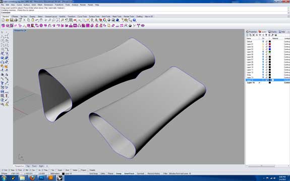
The next step was to create a followed out interior for extra entilation which will increase cooling of the laptop while placed on the stand.
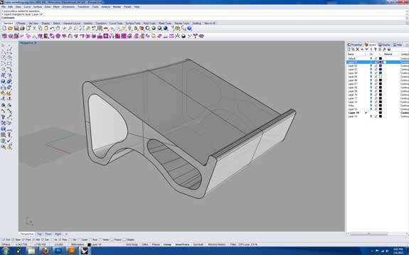
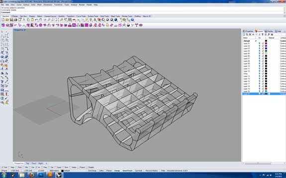
The image above thows how the two sets of surfaces combine to become a full solid model of the laptop stand.
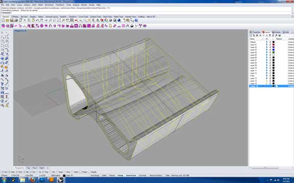
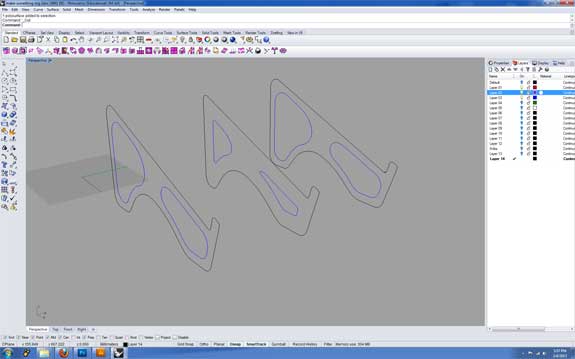
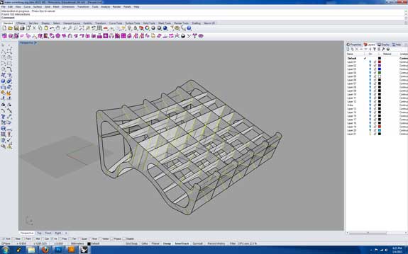
Now that I have my design I will need to prepare it for fabrication. I will want to use sections as in a waffle structure so that more air will flow into the laptop and keep it cool while working on large files. I used the 'contour' command in Rhino and set it for te y-axis.
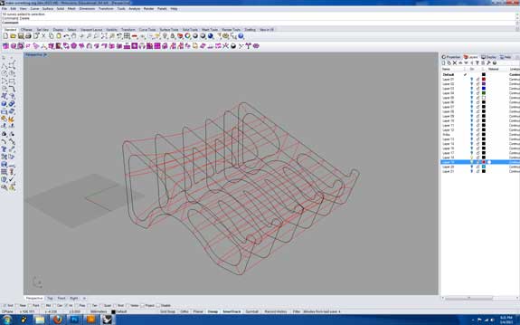
Next, I repeated the contour command for the x-axis (shown in Red) so that I have a full set of parts for fabrication.
Above is a representation of the parts I will need to fabricate the laptop stand. What we still need to do is boolean the joints so that it will fit together once we have laser cut the parts.
To fit them together I ran a command 'intersect' which creates a set of lines where the surfaces intersect with eachother. I split the lines created with the intersect command in two, one will be used for the x axis parts and the other line will be used to boolean the y-axis parts, so that the slots will fit together.
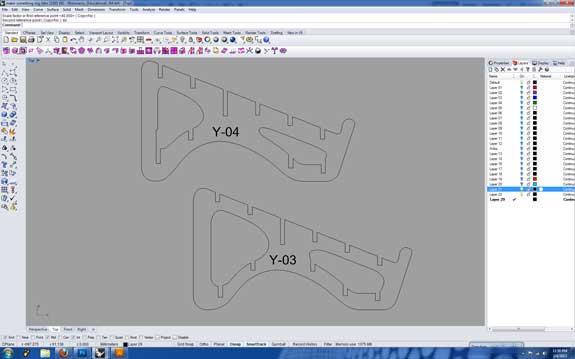
This is the final result, showing the parts with slots booleaned out and ready for fabrication next week during our computer controlled cutting session.
Using Rhino 3D for my final project proposal
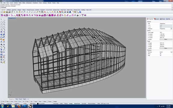
The image above shows a first concept of my final project, a fabricated pavilion that will be controlled by environmental sensors. As I have a background in architecture, I have been working with 3D CAD for a long time. Rhino in combination with Grasshopper is an extremely powerful modeling tool that I will be using a lot during the course to work on my final project.
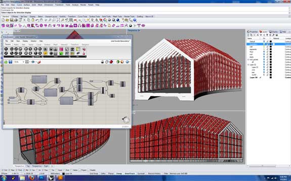
The image above is the smae model but largely rebuilt in Grasshopper, where the skin of the structure has been subdivided and will be used for analysis in environmental factors such as solar radiation.

