06. Electronics Design
Jump to: Getting Started With Eagle | Eagle Tips and Tricks | Exporting from Eagle
This week is an introduction to electronics design. We will be downloading and installing Eagle (an electronics design software program) to make our own custom boards. In week 4 we learned how to mill boards, something we will be using again this week.
![]()
Getting Started With Eagle
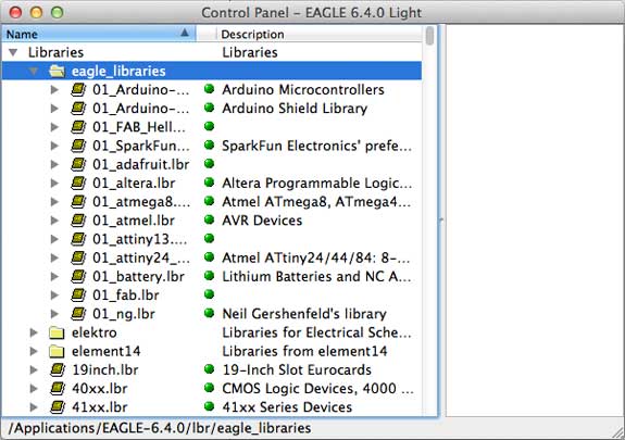
To begin we downloaded and installed Eagle from Cadsoft's server, install the EchoHello folder as well as the libraries folder. Make sure to select 'use' on the specified folders (shown below in green).
The next step was to read up on what a schematic is, learn about electrical concepts and also what the various schematic symbols mean. In addition we read what a board layout is and what it looks like.
Eagle Tips and Tricks
How to Use Eagle
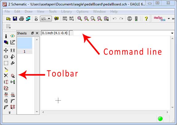
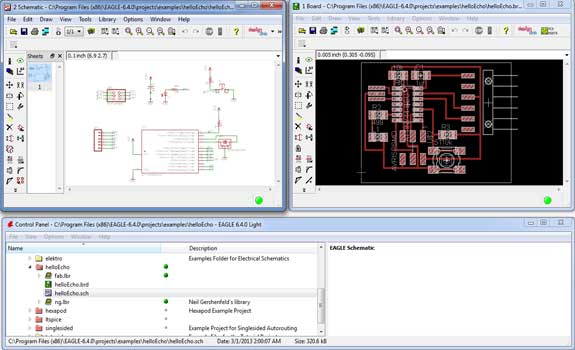
The image below shows the interface set-up of eagle as a combination of two windows (the schematic and board layout). The board is a visual representation of the actual board that is going to be milled. This makes it easy to find mistakes in the layout as you can often easily identify issues just by looking at it.

It is important not to close either .sch (schematic) or .brd (board) files as they need to be open simultaneously. A large warning will pop up making it easy to identify that one of the windows has been closed. Eagle needs both windows to be open at the same time to work properly, not doing so can cause huge problems with he board.
Edit the Schematic
In order to get the desired board we had to edit the schematic. This was done using one (or both) of two options. The first option was by selecting the correct icon in the toolbar to the left of the screen. Or even simpler by simply typing a desired command into the command line.
How To Add / Connect Components in the Schematic
The following step was rather straight forward, it took some time to adjust to and understand the interface, but was relatively simple to do so. The following process was to add components to the schematic and board and arrange them in the right order.
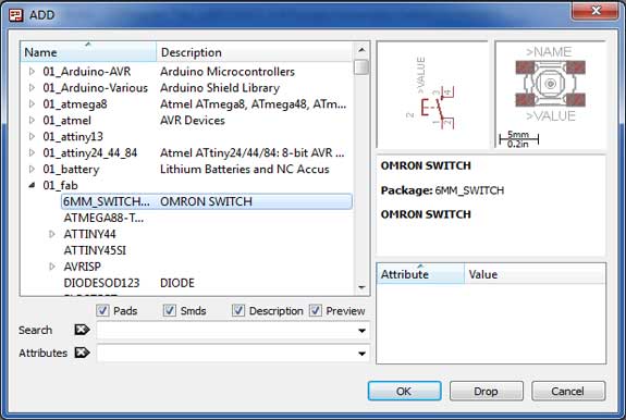
To do this I simply dragged and dropped all the component we needed for the board. Placing them in a random location in the schematic to be organized at a later point. This way I cold make sure I had all the components and the right amount first before going on to connect them and giving them a more structured placement.
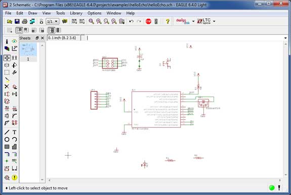
The image above shows how I simply placed everything into the schematic makings ure I have all components before going on to arrange them in the correct order.
Exporting the Board for Milling
In order to mill the board we need to export it as a readable file for the Roland MDX-20. As with the FabISP we need to export the board as a PNG file type. The process to do this is very simple: while in the broad window select "File" --> "Export" --> "Image" and choose a location, select monochromatic or gray-scale and change the resolution to 500 DPI.
The image above shows the final board and schematic that I will use to export to a PNG for use with the Roland Modela and the Fab Modules.
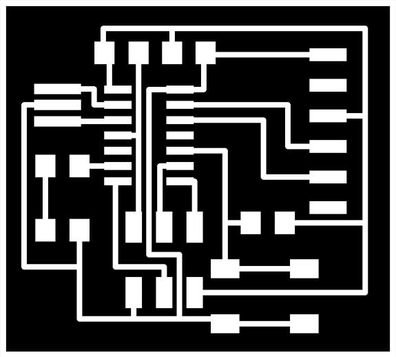
The image above shows how to the mill will route the Traces on the Board. Just like with the FabISP, the Roland MDX-20 will mill away the black and keep the white.

The image above shows the exterior milled area to separate the board from the rest of the copper sheet. In the example file the interior was black and exterior white, this however caused problems for some who had a very close border. The Black is what the Roland MDX-20 mills, so placing it on the outside will ensure your board is safe. Even though it is easy to add some extra space to ensure there is enough room to mill around it, I will stick to the white interior with black border.
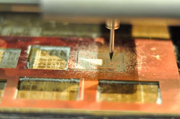
Milling the board using a 1/64 end mill to get the best detail on this relatively small pcb. Due to its small size it takes approximately 10 minutes to mill the traces (better double check to make sure the file is correct before milling).
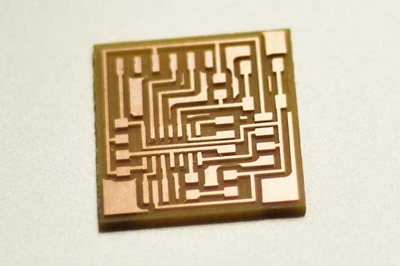
Milled board ready for attaching components. Before I will start soldering components to the board it is a good idea to wash it with water and soap to make sure it is free from oils (from your hand), dust or anything that might make connecting components more difficult.
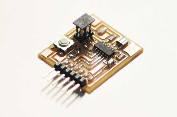
Completed board with components soldered on it. A lot less complicated than the FabISP as there were less components and had had some practice already (starting to get better at it!).
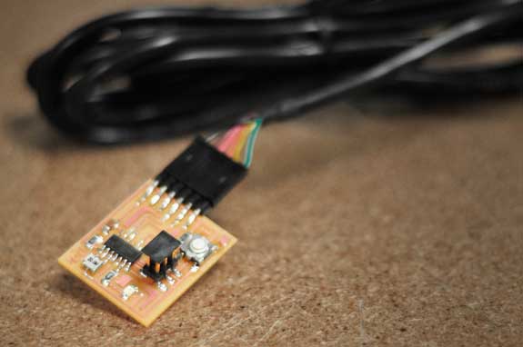
The final result, ready to be programmed and used for an upcoming week where we will use the FabISP to set up the board for use with Arduino software.

