Principles and practices, project management
interface and application programming
mechanical design, machine design
CASULO
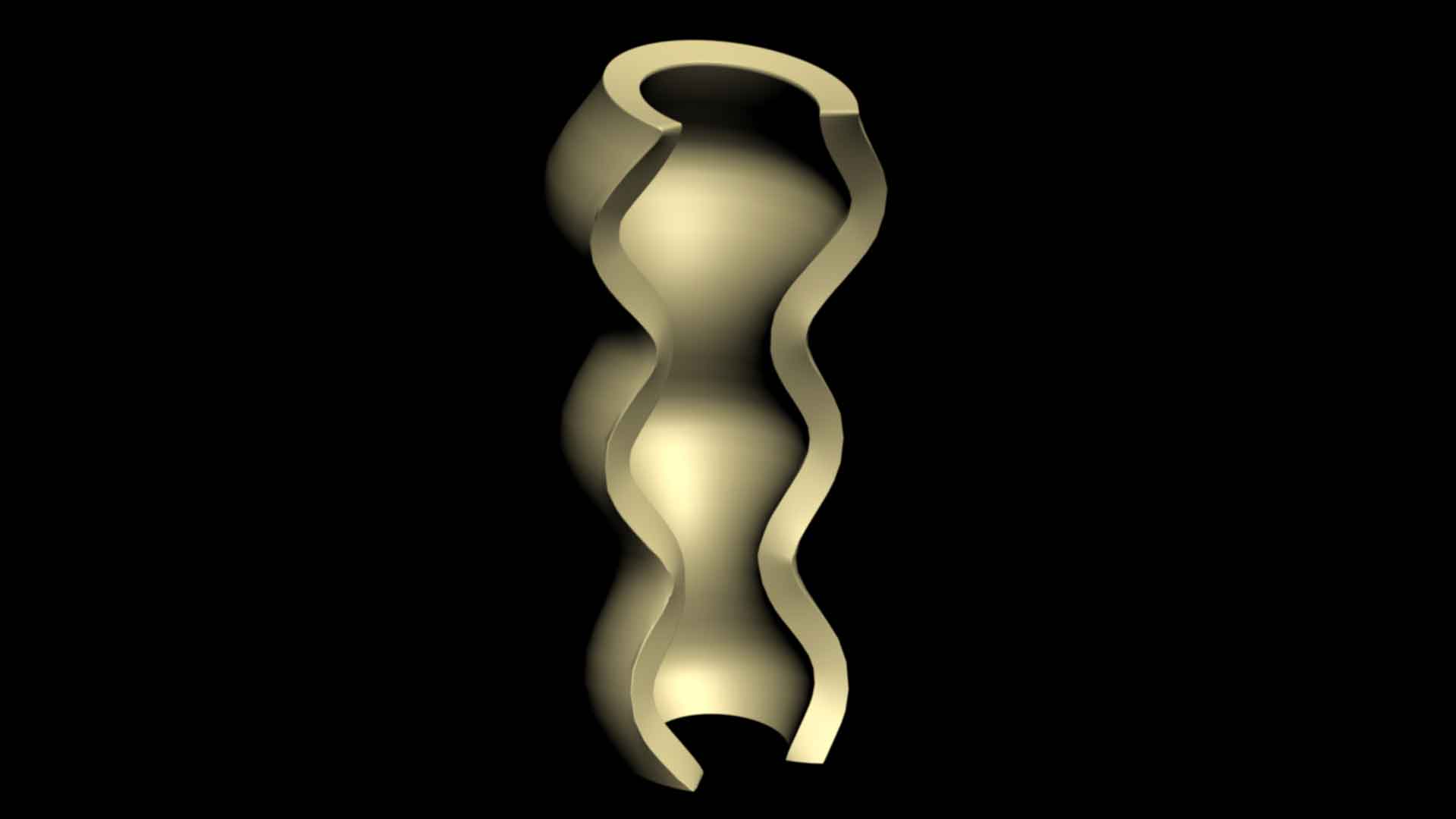
Since the course started, this week was the most busy! The idea was to create something big and to achieve this task I worked together with an artist. The artist, Alessandra Rodrigues has an artwork named “Casulo” (Cocoon) that was created in a tridimensional software. The sculpture was designed to shelter a person with an average size (1,70m). The cocoon was meant to be sliced along its vertical axis many times to give a texture to its surface.
We decided to start by fabricating a smaller sculpture in order to check the stability of the piece.
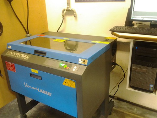
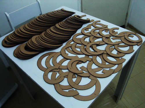
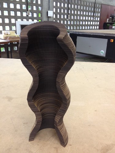
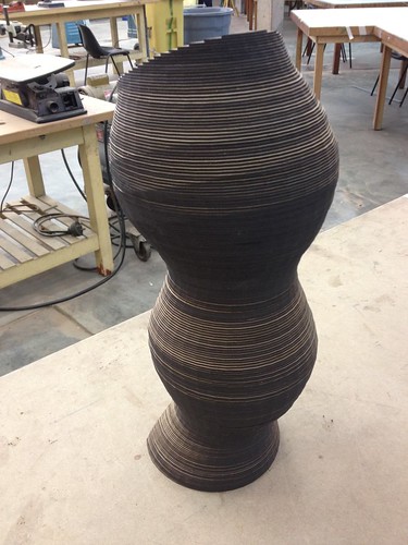
First Experiment – Laser Cutter
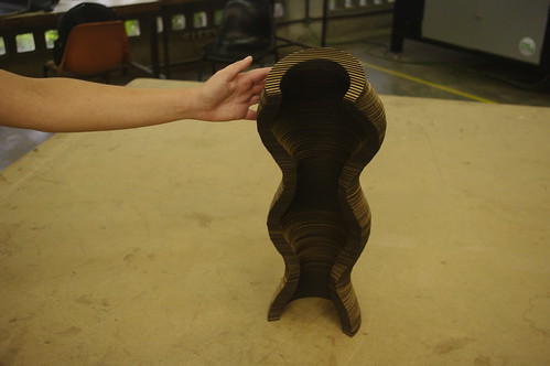
For this first experiment, we scaled the original file so that the sculpture would have 40 cm height. The idea was to slice the sculpture, cut the layers in a laser cutter and paste the pieces together to create the sculpture. In Rhino 3D, we sliced the sculpture in equidistant layers equivalent to the material thickness that we were going to use (2mm Holler paper). We ended up with 222 layers that were spread in several sheets of 60x30cm according to the laser cutting area. We used a total of 23 sheets of Holler paper and each one of them took approximately 8 to 10 minutes to finish cutting. All the layers were numbered so that the assembly would be easier. The 222 layers were then glued one by one with white glue.
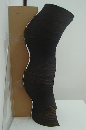
What we learned from this experiment:
- Before starting to glue the layers together, one should have a guiding shape to orient the final shape to be as equal as possible to the original. We made the mistake of not having one of this at the start but we noticed the problem quite in the beginning and we needed to remake those layers and start all over again.
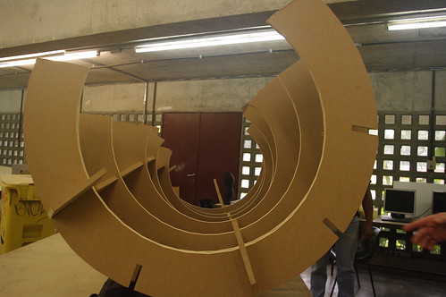
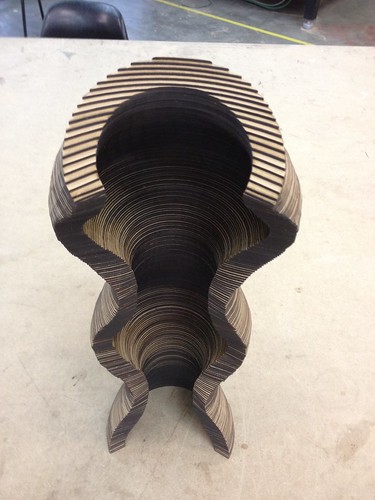
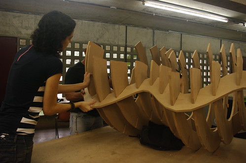
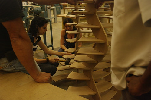
Second Experiment – CNC Milling Machine
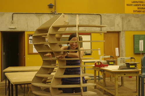
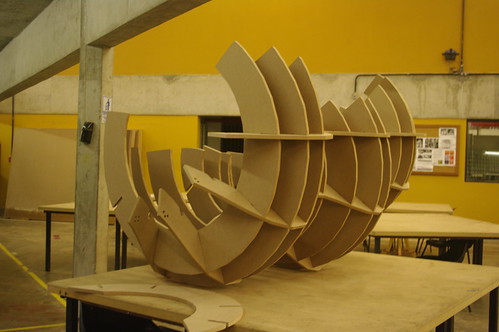
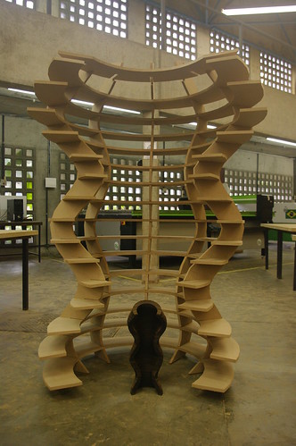
The initial idea was to reproduce the same method of adding the layers together (like in the first experiment) but now in a larger scale (1,80m) using a CNC milling machine. We realized that with the material we had (15mm MDF) the sculpture would be extremely heavy and hard to move. Other problem would be to glue the layers together, we would have needed a pneumatic tool to keep the layers together in order to avoid pressing the amorphous set altogether. So we decided to try a different construction technique that would use less wood and press-fit joints.
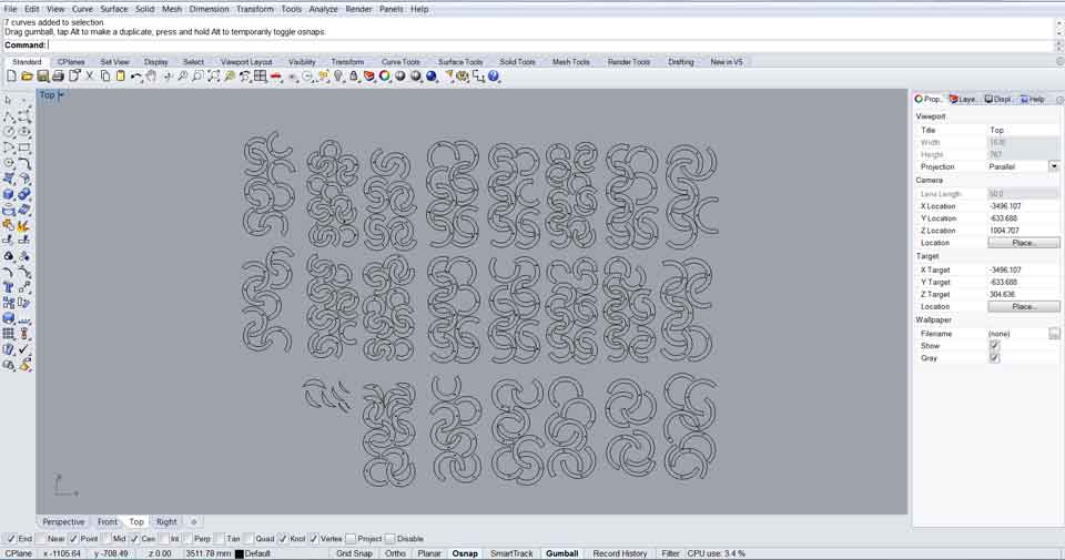
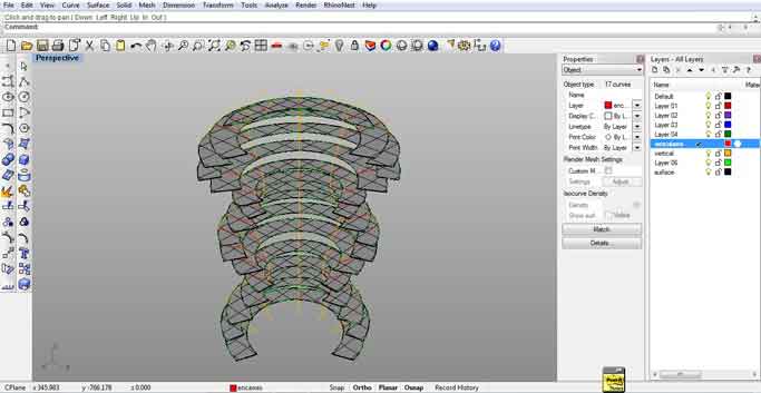
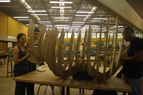
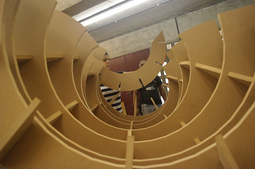
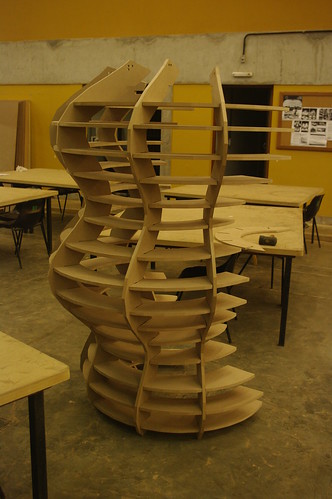
We started by editing the digital file of the cocoon sculpture in Rhino 3D in order to obtain 16 equidistant horizontal layers and 5 vertical layers. The vertical and horizontal shapes would fit with each other and for this I had to create joints for each connection. After having the pieces designed I numbered the horizontal layers making sure the numbers would be on a hidden layer, so they would not interfere in the final wood shapes. For the vertical layers I made a different rule on numbering the sheets, I placed holes (1 to 5) in the top of the sculpture defining which layer is which. Those holes were supposed to appear in the final sculpture, so I did not worry about hiding them in some layer. We had some problems to open the file in the Vcarve (Milling machine software) because it was the first time I did that alone, but we found out how to save the file correctly and fixed the problem. It took an entire day to prepare the files and cut all the pieces with the CNC milling machine. When we started assembling the pieces we realized that we should have had numbered the faces of each horizontal layer. It took us time but we learned during the process. When we finally found the right positions of the horizontal and vertical pieces the press fit was perfect!
Computer-Controlled Machining - 2nd Experiment from Juliana Henno on Vimeo.
What we learned from this experiment:
- I highly recommend making sure to number all the faces of your pieces. We would have saved lots of time if we would have known it from the beginning.
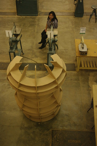
- Because the connections between our pieces were angled, we found a good system to assemble the piece, starting with the central vertical layer (that was placed horizontally on the table) and placing on the top of it all the horizontal pieces. After that we connected the other four vertical pieces to lock the sculpture. Only when the set was assembled we placed the sculpture upright on the floor.
-----
I must point out that it would have not been possible for me and Alessandra to complete this large size sculpture without the precious help of the lab team (Edmilson, Emilio, Julio, Ricardo, Neto, Walter), Santi Fuentemila that helped us to think about the structure and Alex Garcia that helped me with the design of the joints in Rhino 3D. Thank you all!
----
Softwares: Rhino 3D / Cut3D
Hardwares: Laser cut machine / CNC Milling Machine
Files: Experiment 1 / Experiment 2