Principles and practices, project management
interface and application programming
mechanical design, machine design
FAB LUDO
The interactive game we decided to do as a final project is called FAB LUDO. This game is an adaptation of the real game LUDO as we tried to simplify it to the minimum we could. The original game has four players and each of them have four tokens that need to navigate through a game track of 52 squares that start from a staging area and end on the finish square. The adaptation we made was to shorten the number of squares of the game track from 52 to 22 and reduce the tokens for each player from 4 to only 2.
We believe that by doing this adaptation we managed to simplify the electronic interface to something that we, as a team of two could risk to do.
What we have done so far:
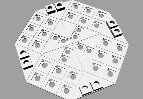
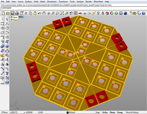
- We designed the new board reducing the number of houses;
- Defined the game rules as well as it´s interface to facilitate the electronic design of the circuit board;
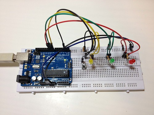
- Did several tests initially using Arduino (Uno rev3) and a protoboard in order to predict the programming of the button trigger and the random LED blink (1 to 3 houses ahead).
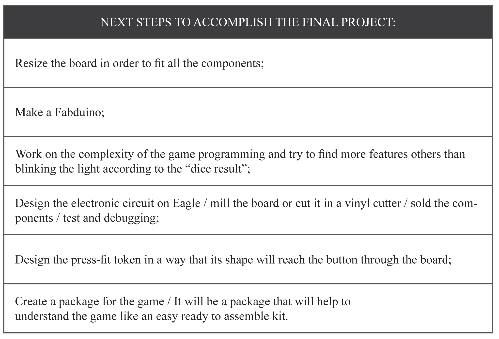
Next steps to accomplish the Final Project:
Project Development
While we were reviewing the LUDO rules we thought about how to adapt them to become interactive in an electronic board.
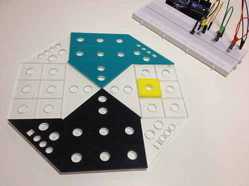
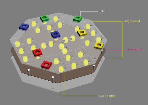
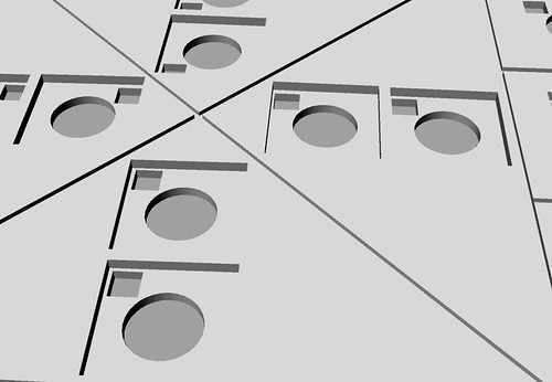
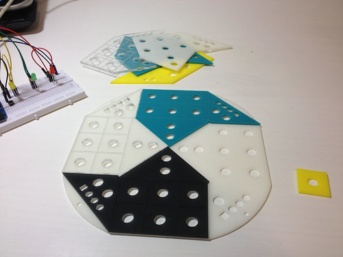
First issue we faced was how our board would look like and in which material we could construct it in order to benefit from the digital fabrication tools and machines we had in our Lab here in São Paulo. We decided that we should make our board in crystal acrylic that would be laser cutted in order to give it the exterior regular octagonal shape and engrave the edges of the game track upon its surface. The acrylic surface was a good choice because the player could see through the board the electronic circuit and maybe (depending on his know-how to understand the connections between the components).
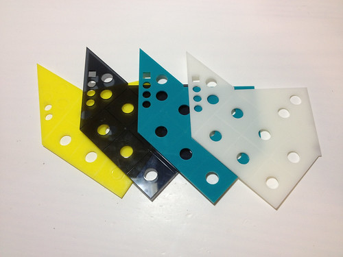
In order to distinguish the areas of each player, we decided to add a layer of a very thin coloured transparent acrylic in a shape that identify the exclusive area of this participant (staging area + home column + finish square). The colours would correspond to the original LUDO and would be: blue, red, yellow and green. By adding separate layers we made possible that the player could choose the order the areas would appear on the board.
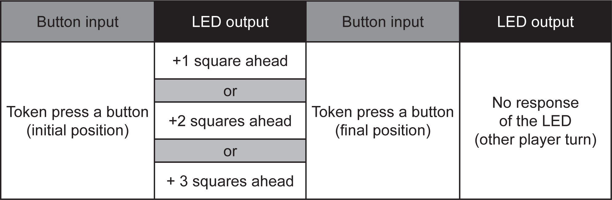
The tokens are limited to two per player, this means that the game will be easier and fast, so to make the game less boring we decided that the dice would give only 3 possibilities: 1, 2 or 3. This way the rush to the final square wouldn´t be fast and the game would last longer.
The traditional roll the dice will be replaced by a button activation that would randomly choose a number from 1 to 3. The button will be placed below each square of the game and will work like a sensor. The tokens will be responsible to trigger the buttons by press fitting them against the board. When the button is pressed a random value is given and this information will go to the respective LED that illuminates the house in which the player can position his token in the present move. By showing the player his possibilities we imagined that the game would achieve an interactive character, always responding to the players actions.
Programming the protoboard:
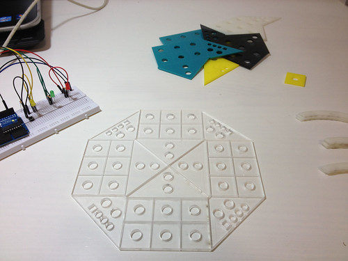
Before going to Eagle and design the circuit board of the game we decided to try the action that will be responsible for the tokens movement separated on a protoboard.
After making tests with a protoboard we got to a conclusion that we will need to scale the board, making it larger, in order to fit comfortably all the components and its connections.
The next step is to continue the tests but milling a real board after designing it on Eagle.
While we did not advanced to this step here goes the code we used:
//Declaração das constantes referentes aos pinos digitais.
const int ledYellow = 8;
const int ledGreen = 9;
const int ledRed = 10;
const int botao = 2;
//Declaração da variável que possuirá os estados do botão.
int estadoBotao = 0;
int r;
//Método setup, executado uma vez assim que o Arduino é ligado.
void setup() {
pinMode(ledYellow,OUTPUT); //Definindo pino 8 como saída.
pinMode(ledGreen,OUTPUT); //Definindo pino 9 como saída.
pinMode(ledRed,OUTPUT); //Definindo pino 10 como saída.
pinMode(botao,INPUT); //Definindo pino 2 como entrada.
}
//Método loop, executado enquanto o Arduino estiver ligado.
void loop() {
r = random (1,4);
estadoBotao = digitalRead(botao);
if (estadoBotao == HIGH) {
//Acendendo os leds caso o botão esteja pressionado, com
//um intervalo de tempo (delay) entre os acendimentos para
//criar um pequeno efeito.
if(r == 1) {
digitalWrite(ledYellow,HIGH);
delay(500);
digitalWrite(ledYellow,LOW);
delay(500);
} else {
if(r == 2) {
digitalWrite(ledGreen,HIGH);
delay(500);
digitalWrite(ledGreen,LOW);
delay(500);
} else {
digitalWrite(ledRed,HIGH);
delay(500);
digitalWrite(ledRed,LOW);
delay(500);
}
}
} else {
//Apagando os leds caso o botão não esteja pressionado.
digitalWrite(ledYellow,LOW);
digitalWrite(ledGreen,LOW);
digitalWrite(ledRed,LOW);
}
}