
Principles and practices, project management
interface and application programming
mechanical design, machine design

Update on programming the board:
The reason why my board didn´t work previously was because I soldered the LED in the wrong direction. After changing it´s position and trying to program it again the LED started to work when I pressed the button.
<
IMG 2357 from Juliana Henno on Vimeo.
>----
For this week assignment we had to program our Hello Button with LED board. To accomplish this task we had to use the FABISP circuit board designed and programmed previously.
About the FabISP board:
Just in case, we built several FabISP boards in our lab in order to avoid possible problems like not having a programmer. This was a good experience, because by doing all the steps (designing/milling/soldering/testing) we learned much more about electronics. Soldering the components into the board was an interesting experience, I had done it before but never with so small components. We learned that some components won´t work if they were placed in wrong directions and that if the soldering wasn´t correct it may affect the component operation. We were not able to find in Brazilian market the right diode for the FabISP board, so we chose an alternative diode that we placed in the boards.
After our “Hello button with LED” board was milled and soldered we started programing the microcontroller (ATtny44A-SSU) that was placed in it. To do it we tried the Arduino Software (1.0.3) that was downloaded from Arduino site. Later we downloaded the Attiny Board Files, so that the Arduino IDE (integrated development environment) could talk to the microcontroller. Then I placed the unzipped folder “Attiny” inside the “hardware” folder that I created at (Library / Documents / Arduino). We had also to install the FTDI Drivers.
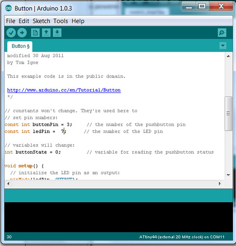
Arduino software parameters before starting programming:
After placing the microcontroller board files into the Arduino hardware folder I launched the Arduino 1.0.3 software and checked if the ATtny44A was listed among the board options. So I checked the ATtny 44 (external 20 MHz clock) in the tool section – as there is an external 20 MHz resonator on the “Hello button with LED” board. Also in the tool section I made sure that the “programmer” was listed as “AVRISP mkII”.

Steps for programming the board:
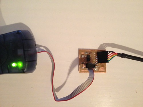
First I provided power to the microcontroller by connecting it to my FabISP programmer. Then I was supposed to connect the programmer to the ISP header of my “Hello button with LED” (which was powered by the FTDI cable).
The little problem was that we did not have an ISP cable available to connect both boards. We are currently working to find a new one and redo the same process to be documented here later this week. So we did the programming using the ATAVRISP2.
Burn the bootloader: We run the “burn bootloader” command to configure the fuse bits of the microcontroller so it runs at 8 MHz.
I placed a code that was provided at the as220.org website. And changed the pin numbers to the corresponded pins used for the LED and button.
/*
LED Off Until Button Pressed
Blinks a light emitting diode(LED) connected to digital
pin 7, when pressing a pushbutton attached to pin 3.
The circuit:
* LED attached from pin 7 to ground
* pushbutton attached to pin 3 from +5V
* 10K resistor attached to pin 3 to +5V
* 10K resistor pulls pin 3 and the button to HIGH by default
created 2005
by DojoDave
modified 30 Aug 2011
by Tom Igoe
modified for Hello Button + LED Board - 19 Mar 2012
by Anna Kaziunas France
*/
// constants won't change.
// They're used here to set pin numbers:
const int buttonPin = 3; // the number of the pushbutton pin
const int ledPin = 7; // the number of the LED pin
// initialize variables:
int buttonState = 0; // variable for reading the pushbutton status
void setup() {
// initialize the LED pin as an output:
pinMode(ledPin, OUTPUT);
// initialize the pushbutton pin as an input:
pinMode(buttonPin, INPUT);
}
void loop(){
// read the state of the pin the pushbutton is connected to:
buttonState = digitalRead(buttonPin);
// is the push button pressed?
// if not pressed - the button state is HIGH
// the pull up resistor the button / pin 3 makes the button state HIGH by default.
if (buttonState == HIGH) {
// turn LED off (LED is off by default)
digitalWrite(ledPin, LOW);
}
//otherwise.....
// button is pressed
else {
// turn LED on:
digitalWrite(ledPin, HIGH);
}
}
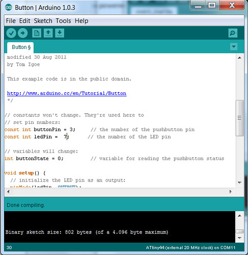
Verify and Upload:
After placing the code and changing its port reference I verified the code:
After verifying I uploaded it to the board:
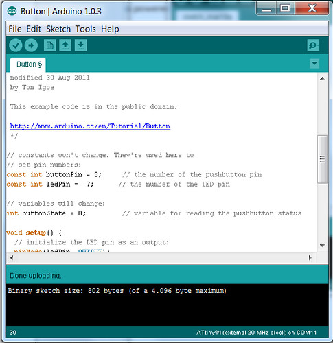
The uploading was successful but the LED did not shine when I pressed the button.
I suppose that the problem was with the circuit and I´ll built a new board to try the steps one more time.