Principles and practices, project management
interface and application programming
mechanical design, machine design
INPUT DEVICES
This week´s assignment was to add a sensor to a microcontroller board and measure the results. Because of my past surveys on the theme colour as a light source, I decided to measure light.
Since the last assignments the electronic theme has been increasingly less scary for me. I´m getting along with this environment and this is helping me to face the new assignments that seem to be getting each time more complex.
After defining the kind of sensor I wanted to work with, I saved all the files regarding the “phototransistor” light sensor that was listed under the assignment official page schedule.
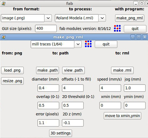
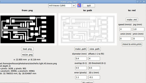
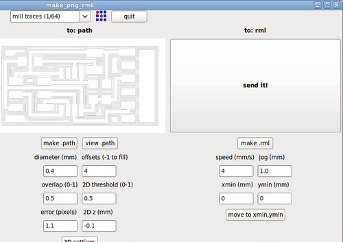
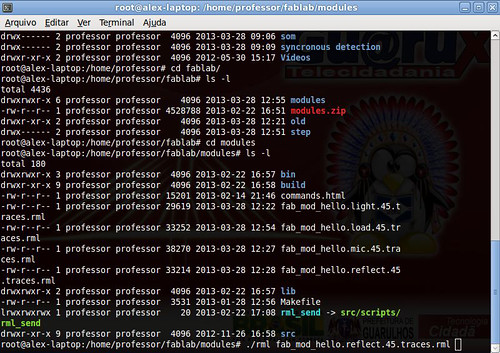
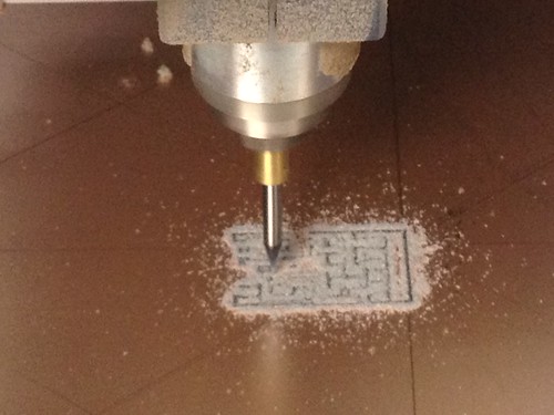
The first step was to mill the board, and for this task I just had to open the traces/interior file in the Fab Modules and send it to print through a command in the terminal to the Modela MDX-40A. We still are having problems setting the X, Y and Z axis from the Fab Modules, because of this we are setting the axis in the Modela software and completing the “send to print” process in the Fab Modules. Just in case I milled two phototransistor boards in case it would be necessary in the programming process.
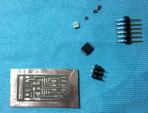
After the boards were printed I started sorting the components. Now it´s getting easier to find the components and this step was completed really fast! I used the “board” page as a reference to find the components.
Once the components were separated I soldered them, always taking as a reference the “board” scheme. The soldering was easier than in the last time and I started refining the techniques I learnt in order to obtain a better looking joints in the board. It didn´t take me a lot of time to accomplish it.
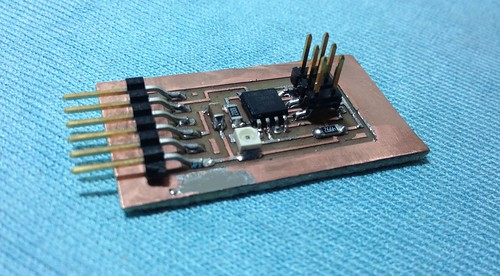
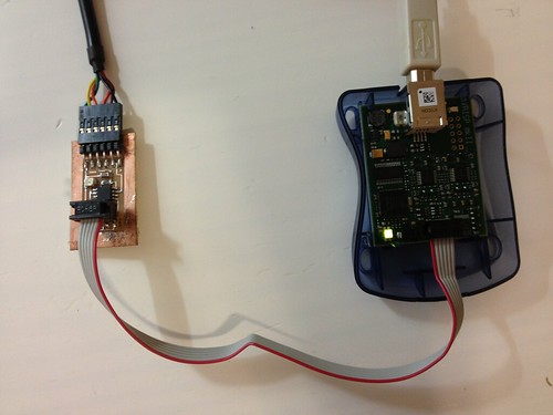
After my board was soldered I started to program it. The first thing was to connect the phototransistor board to the programmer (AVRISPmk2). My FabISP was not working correctly, so I decided to use the AVRISPmk2 for this assignment. After plugging the phototransistor to a FTDI cable (to power the board) and to the programmer (through a ISP cable) the LED of AVRISPmk2 went green, that was a good sign!
The programming is still a huge task for me to solve. I tried programming the board in Windows 7 (64bit) through the Cygwin Terminal but it didn´t work. I tried programming with the Arduino software and it didn´t work either. I also followed the steps on the Providence tutorial and I had no luck. The part of “try to program” took a lot of time and I could not accomplish it before the deadline. It´s too early to say that the problem was with the components position on the board, because the programs I run were not working normally (as I noticed while following the tutorials). I intend to continue with this assignment during the next week in order to keep track on the next electronic-related assignments.
-----
Further progress on assignment #10
After accomplishing the first steps of this assignment, which was printing and soldering the components I stopped at the programming phase due to some difficulties I found. I had some trouble downloading the Cygwin terminal and luckily I managed to install it correctly!
What I installed: Cygwin, Mercurial and Winavr
After installing Cygwin I entered the following command in order to program the board through the ATAVRISP2 programmer:
Juliana Henno@JulianaHenno-PC /home/Light/phototransistor
$ make -f hello.light.45.make program-avrisp2
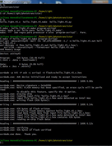
The programming was successful and generated two files that were placed at the Phototransistor folder: "hello.light.45.out" and "hello.light.45.hex".
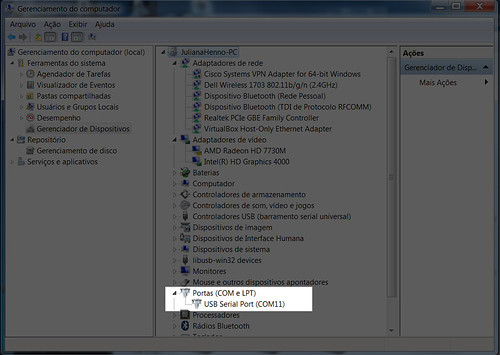
After the board was programmed the next step was to run the Python file (hello.light.45.py) in order to visualize the board working. To do so I had to discover in what USB port my board was connected. As my phototransistor board was plugged to a FTDI cable I noticed my board was connected to the port 11. So I tried to run the Python program.
In Cygwin I tried entering the following command:
--
Juliana Henno@JulianaHenno-PC /home/Light/phototransistor
$ python hello.light.45.py /dev/com11
Traceback (most recent call last):
File "hello.light.45.py", line 67, in <module>
root = Tk()
File "/usr/lib/python2.7/lib-tk/Tkinter.py", line 1685, in __init__
self.tk = _tkinter.create(screenName, baseName, className, interactive, wantobjects, useTk, sync, use)
_tkinter.TclError: no display name and no $DISPLAY environment variable
--
But it didn´t work and I got this error notice.
I´ll continue the assignment this week and I intend to solve this problem in order to keep track with the latest electronic assignments.
(16/04/2013)
--
I tried once again to run Python to visualize my sensor board using Cygwin and it worked. For me it was great to see how far I have reached in the electronics field! I almost gave up on the way but thanks to my fabber colleagues and all the people that are kindly helping us in the Lab I managed to accomplish one more electronic related task!
Until now I was working with the phototransistor board but there was an accident during the manipulation of the board and I could not use it anymore. So I used my second option board: a “synchronous detection spread spectrum” that worked detecting the reflection of a LED light upon the sensor. Because I changed the board I had to do all the initial steps of this assignment all over again.
I first tested the board using AVR (AVRISP2), I connected the board to a FTDI cable and to the programmer (ISP cable) and noticed that the board was well soldered (the green light was glowing). Nice start! With the board connected to the programmer and to the computer I entered into the programming phase. For it I had to download the C file, the make file and the Python file and save them inside the Cygwin folder (C:>Cygwin>home>Light>reflect). The next step was to program the board and for it I used the Cygwin terminal. I typed the following command in order to program my board:
Make –f hello.reflect.45.make program-avrisp2
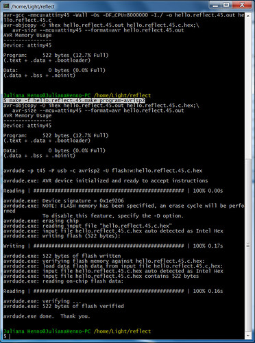
The command was successful to program the Attiny45 microcontroller I had in the board!
Next I identified the port the board was connected to in my computer. I found out that it was port 11. This information will be needed when I run the Python through the terminal.
But until now there was no mystery, I managed to reach to this point using the former board but I was up against a huge task: running Python through Cygwin. The tutorials we found in the internet did not explain how we could run Python from Cygwin because everybody who tried the same experiment had used Ubuntu or Mac as a platform. In our case, in the FabLab SP, we could only use PC, so we had to search in forums how to run Python from Cygwin having a Windows 7 (64bits). The research went well and the fabber Alex Garcia found a site that explained the correct command to run the Python through Cygwin:
Cygstart /cygdrive/c/cygwin/home/Light/reflect/hello.reflect.45.py com11
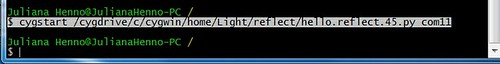
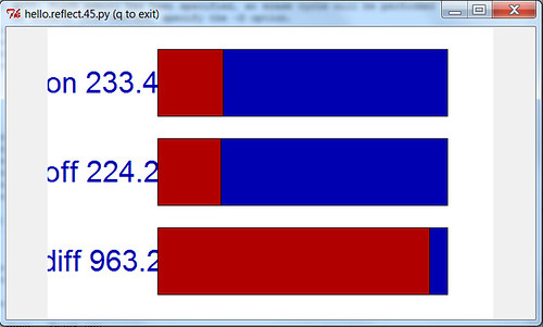
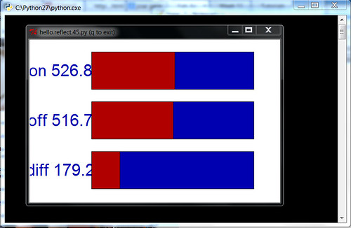
It worked perfectly! And the window with the graphics showing the result of the sensor appeared in the screen:
After succeeding using Cygwin we decided to run Python through the Windows terminal (CMD). The command, that everybody was using in the tutorials to run Python in Windows worked here perfectly! After opening CMD I entered the following command:
Python hello.reflect.45.py com11
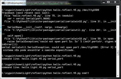
And after that it appeared the graphic window displaying the results of the sensors!
(19/04/2013)