Final Project
Work Desk - RIZER
Sketch
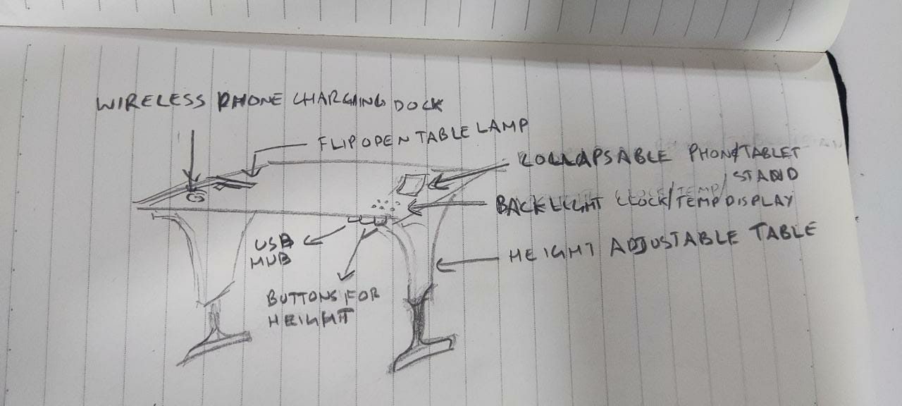
This idea popped up to me one day as I was working on some 3D design for hours and thought for a second if I can stand up and work, and I added to that thought what if we can integrate some more tools into the work desk like a clock, temperature display, maybe even a phone/tablet stand or even a foldable table lamp and many more gadgets like a wireless charging dock, a USB hub which can be plugged into your laptop/PC and even a cooling pad.
What will it do?
The Table should be able to raise and lower its height upto 1100mm with a press of a button in order to accomodate the est comfortable height for the user…
Who’s done what beforehand?
Such a product is available in the market but is on the premium price range by bigger companies like Hafele so my idea is to try to make it as efficiently and make it into a DIY kit
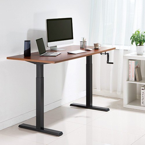
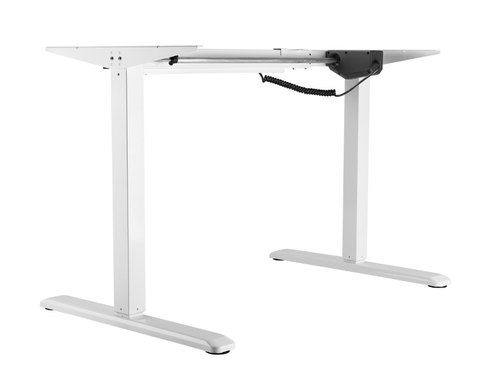
This product comes in both manual and electric motor driven mechanisms
What I did so far…
This is where I am at the start of the final week…

But lets first recap what all I did through-out these 6 months for the final project…
What did you design?
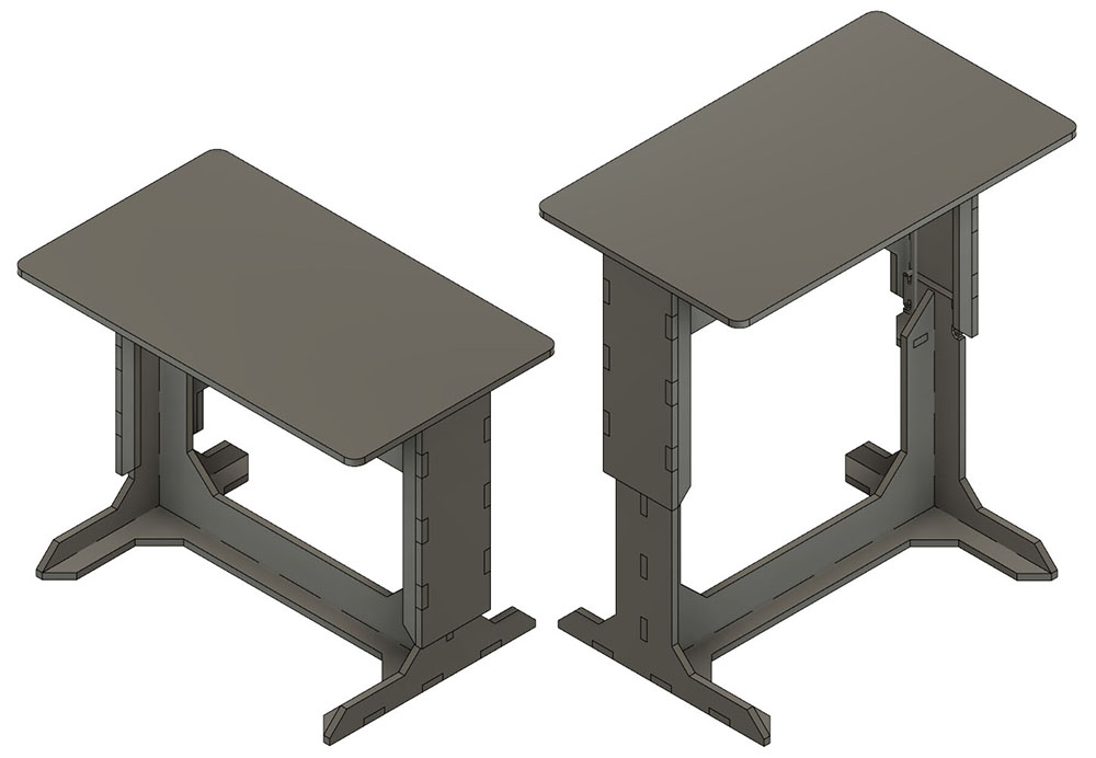
2D & 3D Designing
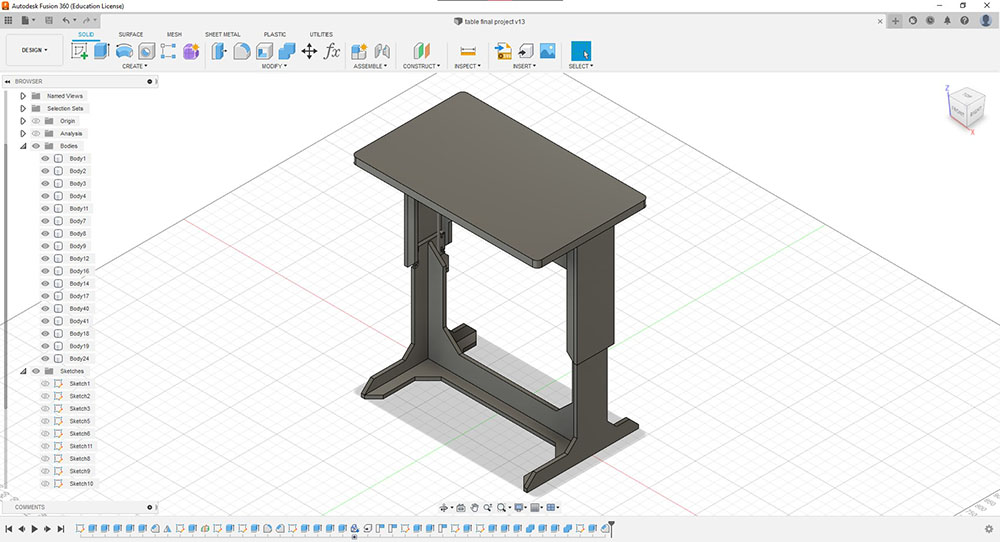
I designed all the parts using Fusion360…
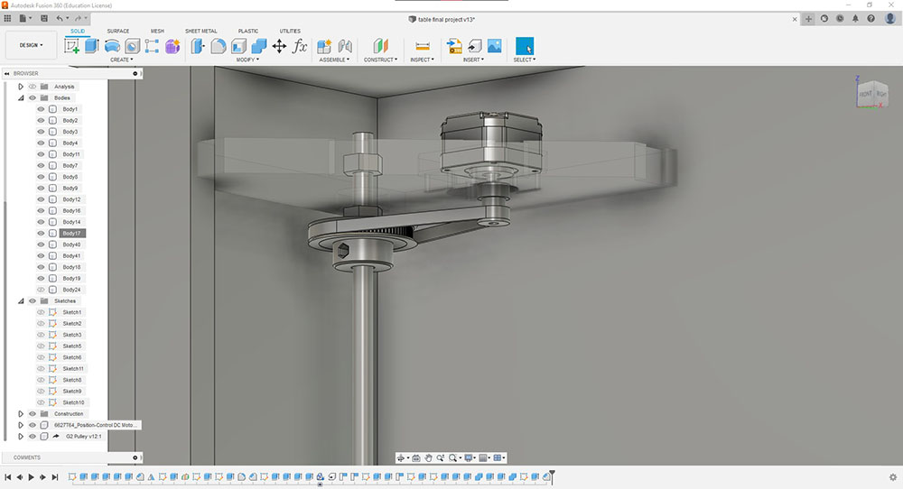 Actuation using stepper motor
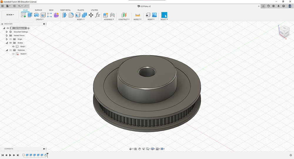 Final design of the gear reduction pulley
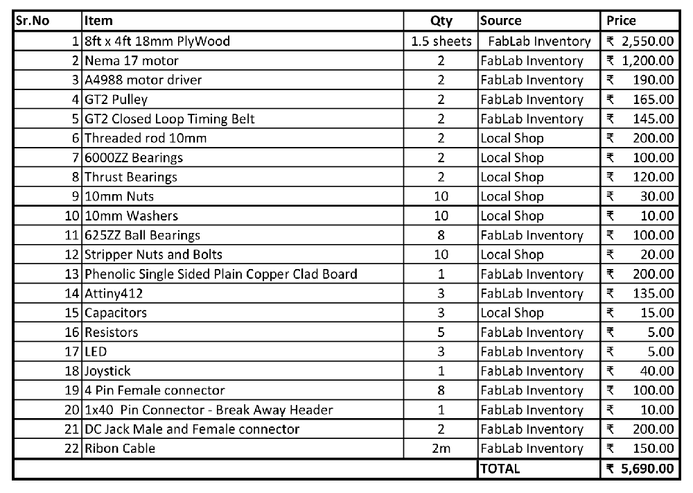
What materials and components were used?
As of now the main table parts will be made of plywood and use 2 stepper motors Nema 17 with a lead screw to raise and lower the height
What parts and systems were made? What processes were used?
Production
I 3D Printed the Gear reduction pulley using the Prusa
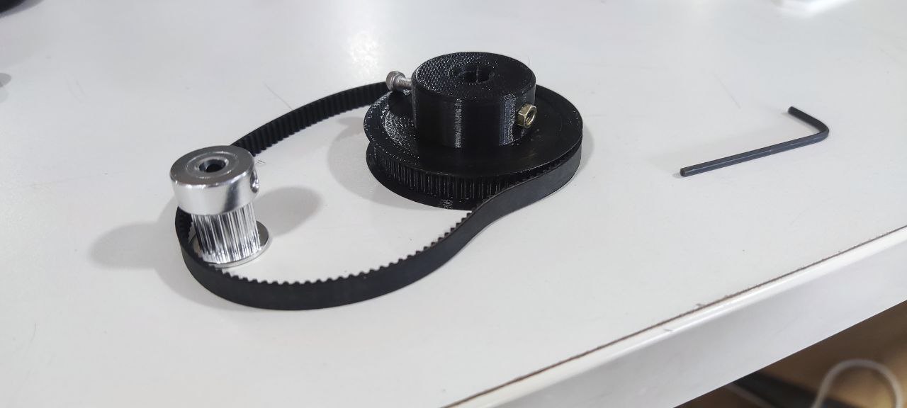 3D printed pulley
Using the ShopBot I cut the main parts of the table…
More details about cutting the parts can be found in Computer Controlled Machining Week
The actuation plate was milled using the ZUND as I wanted to mill on 2 sides and ZUND has a feature in which you can use its camera module to align the peice…
Cutting the top side…
Cutting the Bottom side…
Learn more about the ZUND from Wildcard Week
I also used the Roland MODELA MDX-2
Learn more about PCB Milling and board manufacturing from Electronics Production Week

Stepper Motor Driver Board...
Learn more about Stepper Motor Driver Board I made in Output Week
 Joystick controller board…
Learn more about the Board I made for the Joystick in Networking and communications Week
Assembly
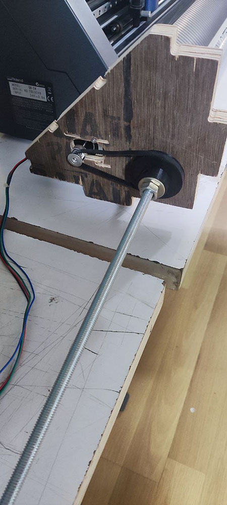
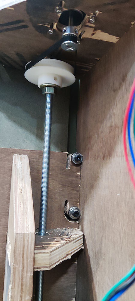
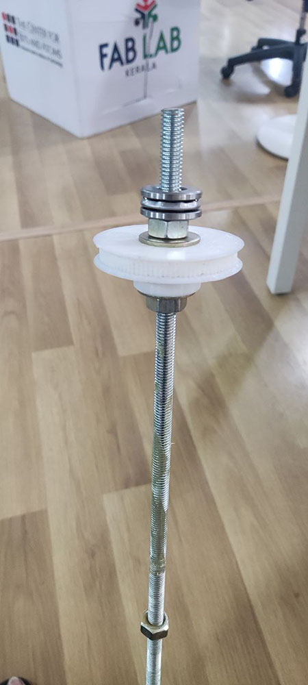
Actuator Assembly
Then this setup was attached to the actuation plate…
Though the pulley is working fine I decided to increase the number of teeth on the pulley and then we attached it to the final assembly onto the table…
What questions were answered?
One of the main question that came up was will the motor have enough torque to lift the weight of the table and so we used gear reduction in order to increase the torque but then the table was lifting much slower than it should have
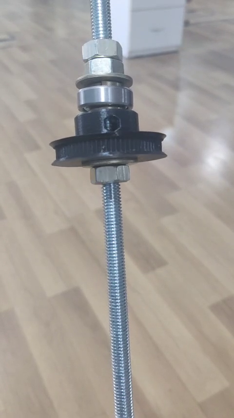
Another question that came up was if the ball bearings would take this load and so we used thrust bearings so that we could use the whole surface for spreading the weight and use the bottom for acuating
<== Before====================================After==>
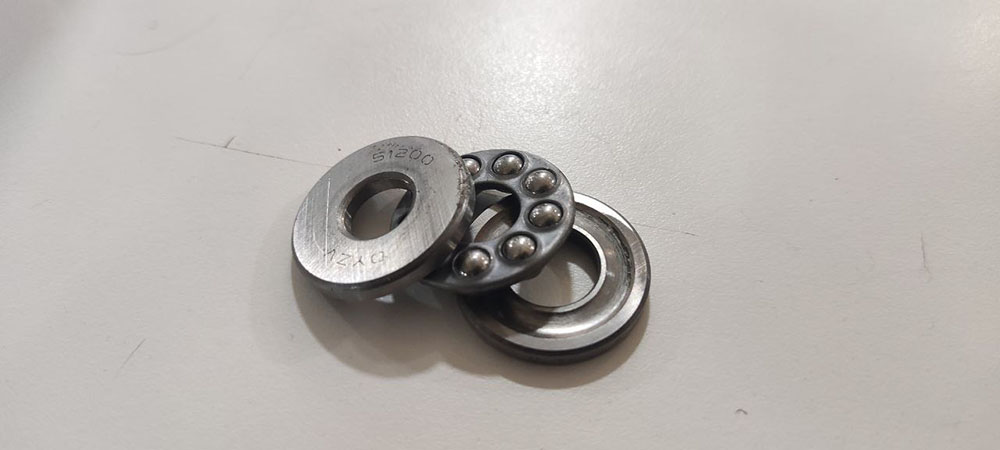 Thrust Bearing
What worked? What didn’t?
Testing
Testing the actuator...
The joystick was fixed under the table towards the right side of the table
I have covered how I communicated the joystick with the Stepper motors in Networking and Communication Week
Since the stepper motor driver I made wasn’t working as efficiently as we expected it to work, we used the RAMPS board to test it…
Time has been sped up
How was it evaluated? What are the implications?
-
Though we were able to use the RAMPS board to lift it, and later when we tried to use the board I made it wasn’t working as effectively and hence will rectify this in the next cycle of development
-
We have also learnt that we would need a stepper motor that has got more torque or else we can just use a DC motor and an encoder and then use that assembly for lifting and lowering the table much faster and more effieciently and I will be looking forward to do that in my next cycle
-
The joystick being a bulky component, I have decided to change from using a joystick to using a capacitive touch buttons for lifting the table in the next cycle

Download my Final Project works