7. Computer controlled machining
WEEK 7
This week’s assignments are:
- Todo the lab’s safety training(Group Assignment added HERE)
- To runout,alignment, fixturing, speeds, feeds, materials, and toolpaths for our machine(group assignment)
- To make (design and assemble) something big (in a meter-scale)
Design Phase
With my past knowledge with CNCs I normally use AutoCAD for making the designs and drawings, and use ArtCAM for making the toolpaths. But since I was getting used to Fusion360 I thought how about I do all the designing and preparing the CAM files within Fusion360.
Since we had to make something big I decided to make a table which I could also use for my final project that way I can save some material
Since I have previous experience designing furniture, and knowing the standards I designed a very basic table that can be assembled easily
I made the design in such a way that it could be assembled by press fit and then converted all the parts into components and then using the “Arrange” Tool in the toolbar arranged the parts in such a way we can project onto a sketch and then import it for making the CAM file

In this window under the “Objects” tab we can select the components and the faces that you want and on the “Envelopes” tab we can select the sketch we want to place it on

After I arranged the parts I added dogbone to the pockets and pressfit joints using a dogbone plugin/extension which I found here
 The result…
I then “Projected” these parts so that I can export it to “.dxf” format so that I can then take it into the CAM software for praparing the CAM files

By selecting and right clicking the sketch we can export to “.dxf”

Then I used VCarve for making the CAM Toolpaths.

Once we open our “.dxf” file we can give the material attributes such as the length, width, and thickness etc., of the PlyWood we are going to use

Then I went and adjusted the file in such a way we can use maximum material for each part using the “move” tool, “rotate” tool, “flip” tool etc.
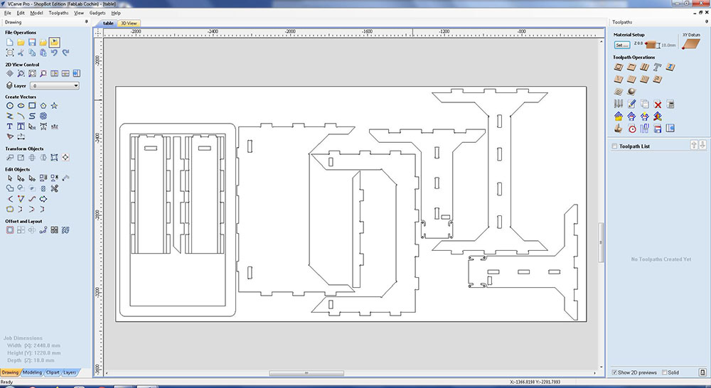
Now in the “Toolpaths” Tab on the right side we can start adding toolpaths and I started by making the toolpath to cut the holes for the ball bearings
 Since I just wanted to mark the holes I used the 6mm Flat End Mill
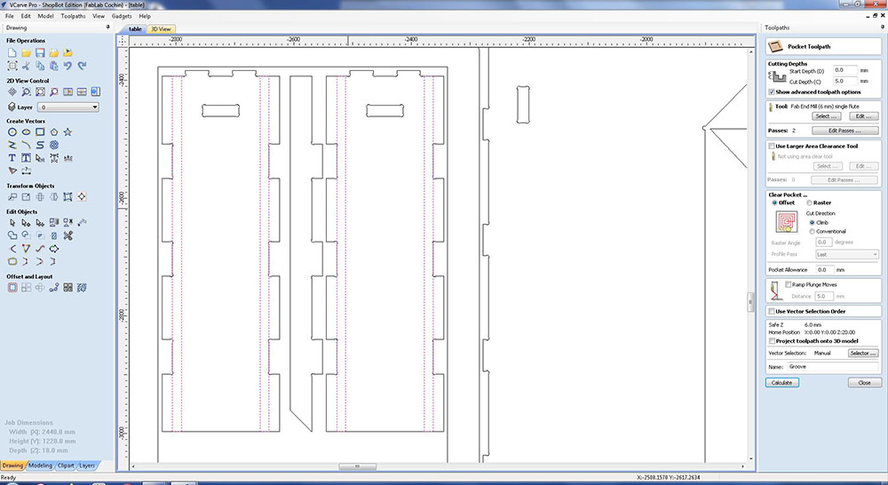
Next I added the “Pocket Toolpath” for making a groove so that there is space for the ball bearings to be bolted to the back
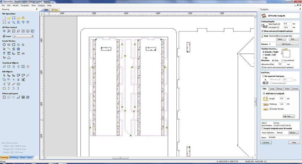
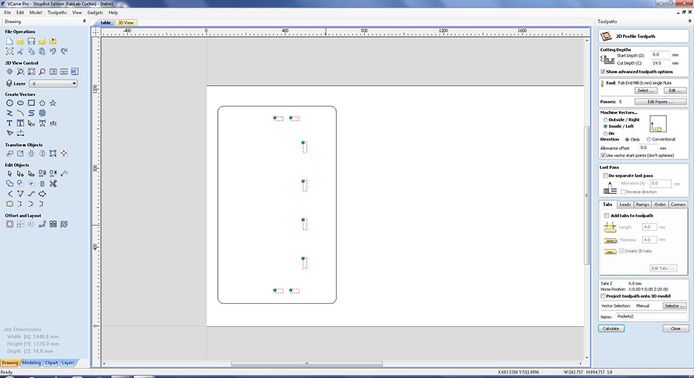
Next I added the pockets for the press fit joints using “2D Profile Toolpath”

And lastly I added the toolpaths for cutting the individual parts
 Always make sure if you want the inside or outside of the part and give the command accordinly

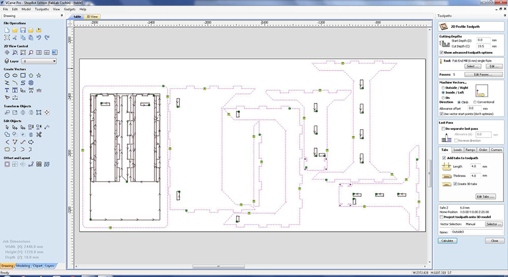 From my previous work experience I always cut the inner pieces first hence I have given it this order
Notice the “T” which are Tabs. During milling/cutting or when the machine finishes cutting a part there is a tendancy for these parts to move around due to vibrations or other various reasons, so these tabs are added that way the peices stay intact until the end of the milling process.
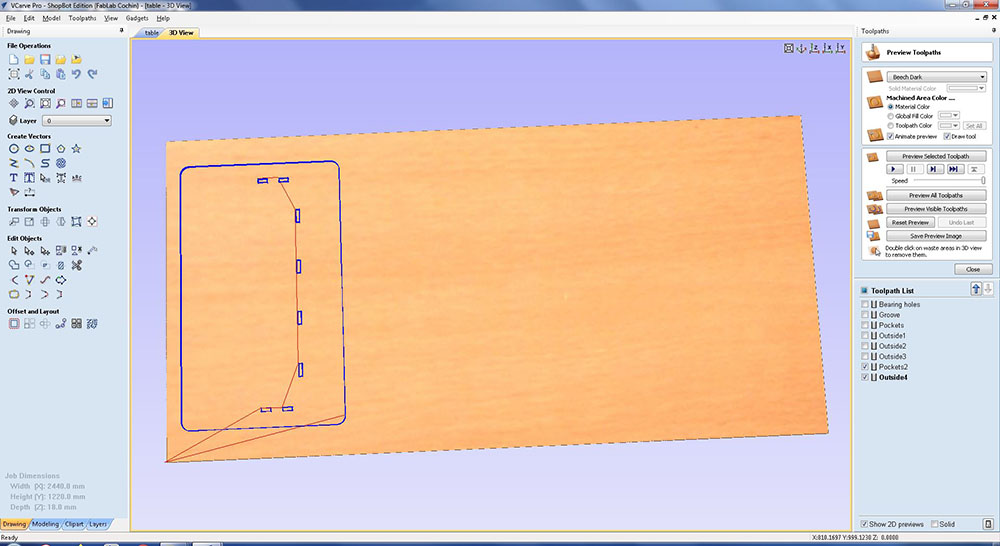
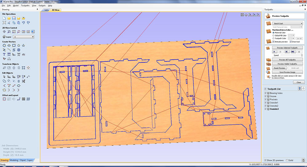 This is a 3D view of what our stock/material will look like after cutting
The Blue lines denote the path of the machine while cutting and the Red lines denote the path when the machine is moving whilst not cutting
We can save these toolpaths by clicking “Save Toolpaths” on the “Toolpaths” Toolbar and then selecting which toolpath you want to save and finally click “Save Toolpath(s) to File”

Since all the parts didnt fit in one single sheet I used a little bit of the left over sheet used by the others at the lab for the table top

Now we can open up ShopBot’s Software to load the CAM toolpath and run the files

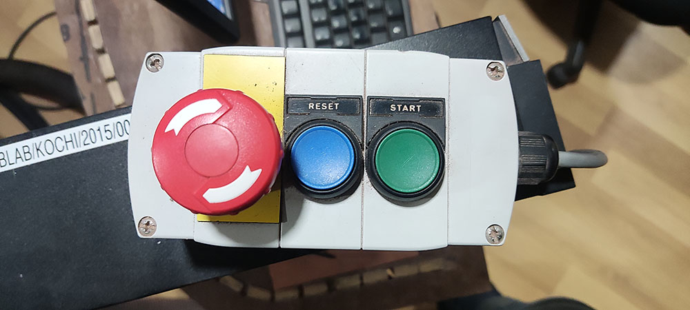
But first we must switch ON the ShopBot found on the side panel of the ShopBot

Once the ShopBot is ON we can open up the software

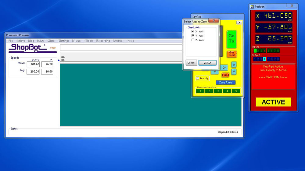
Before loading our file we must first ZERO the ShopBot to the Origin point of our material/stock and can be done by fist clicking on the remote icon…
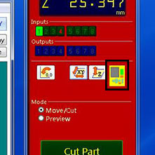
Now using the arrows on the remote or arrow keys we can move our shopbot to the origin point and then click on the “Zero Axes” button and then by selecting the axes and clicking on “ZERO” we can then zero our machine

 Similarly we can zero the Z axis too
And finally we can load our file by clicking on “Cut Part”

Once the file is loaded we can hit “START”

When we click “START” a window pops up asking us to switch on the spindle which also can be turned ON using the key on the side panel of the ShopBot


And also make sure to hit the Start button on the physical remote
Now that the spindle is spinning we can click OK and the machine starts to run the code line by line which can be seen on the “Command Console”

Once the sheet is loaded we used screws to clamp the sheet down so that it doesn’t move around while cutting


Milling…
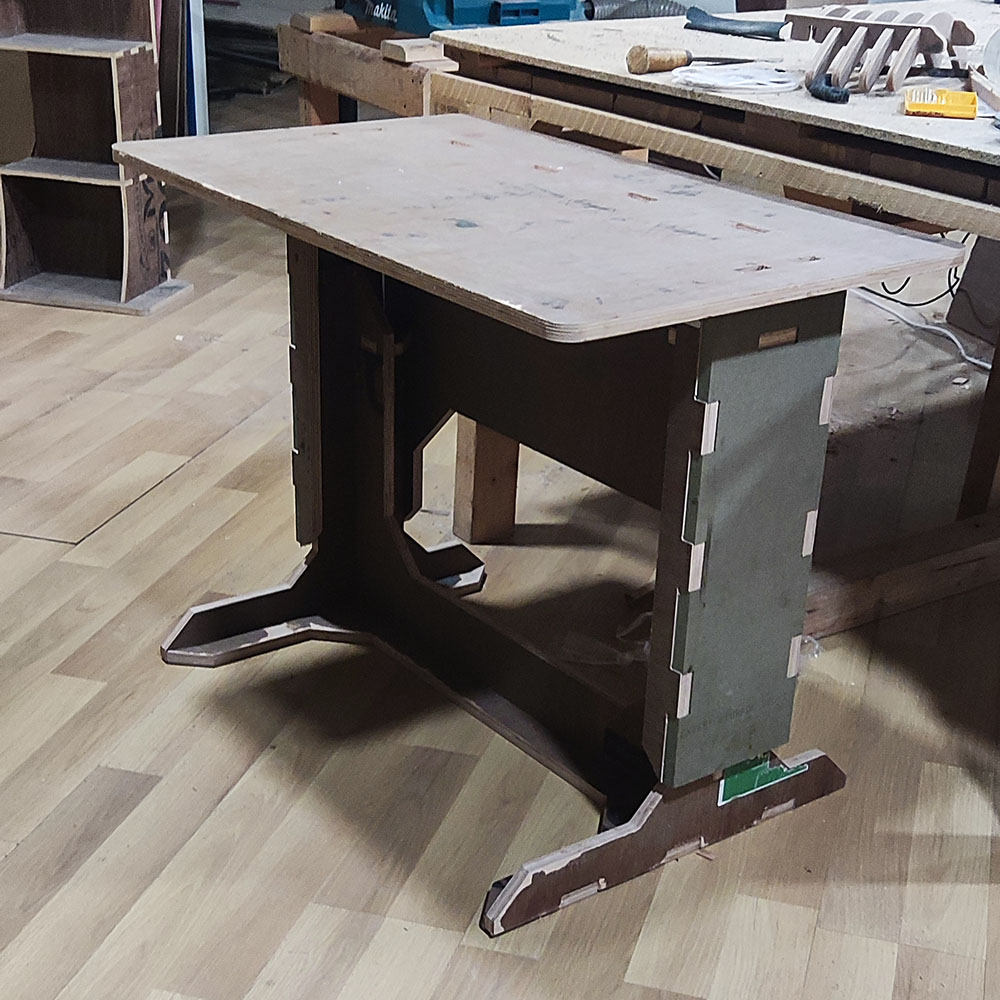 And Finally the end product