13. Networking and communications
WEEK 13
This week’s assignments are:
- To design, build, and connect wired or wireless node(s) with network or bus addresses
- To send a message between two projects(Group Assignment added HERE)
I2C Communication
I²C or I2C communication is the short form for inter-integrated circuits. It is a communication protocol developed by Philips Semiconductors for the transfer of data between a central processor and multiple ICs on the same circuit board using just two common wires.
Since my final projecct required 2 motors and a controller to adjust the height of the table I decided to use I2C to communicate between the 2 motor drivers as slave board and a joystick as the master board
I followed this tutorial and using an Arduino Uno board and the motor driver board I created in the Output Week and used the following code…
Master Board
//Code for the Master board
#include<Wire.h>//This library is used for I2C communication
int x;
void setup() {
  Wire.begin();
  Serial.begin(9600);
}
void loop() {
  x = analogRead(A0);//Reading value from Potentiometer
  x/=4;
  Wire.beginTransmission(9);//9 here is the address of the slave board
  Wire.write(x);//Transfers the value of potentiometer to the slave board
  Wire.endTransmission();
  Serial.print(x);
  delay(1000);
}
Slave Board
//Code for the slave board
#include<Wire.h
int x;
void setup() {
  pinMode (13, OUTPUT);//Connect LED to pin 13
  Wire.begin(9);//9 here is the address(Mentioned even in the master board code)
  Wire.onReceive(receiveEvent);
  Serial.begin(9600);
}
void receiveEvent(int bytes) {
  x = Wire.read();//Receive value from master board
  Serial.print(x);
}
void loop() {
  if (x > 250) {//I took the threshold as 250,you can change it to whatever you want
    digitalWrite(13, HIGH);
    delay(200);
  }
  else{
    digitalWrite(13, LOW);
    delay(400);
  }
}
I used the serial monitor to first check what values each position of the joystick returns and tuned the code accordingly
This was the output I got
Using the above example I designed a board to which we can attach the joystick


And then milled and soldered the components
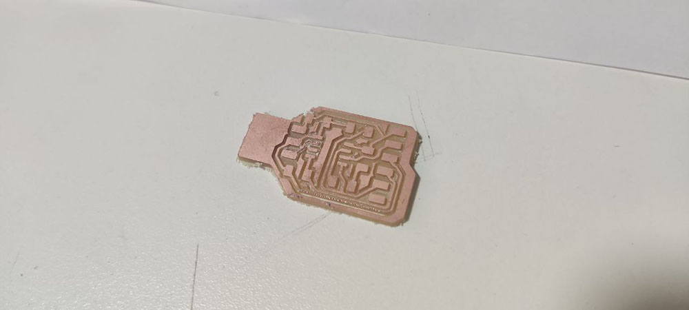

This is why you shouldn’t design past bed-time…
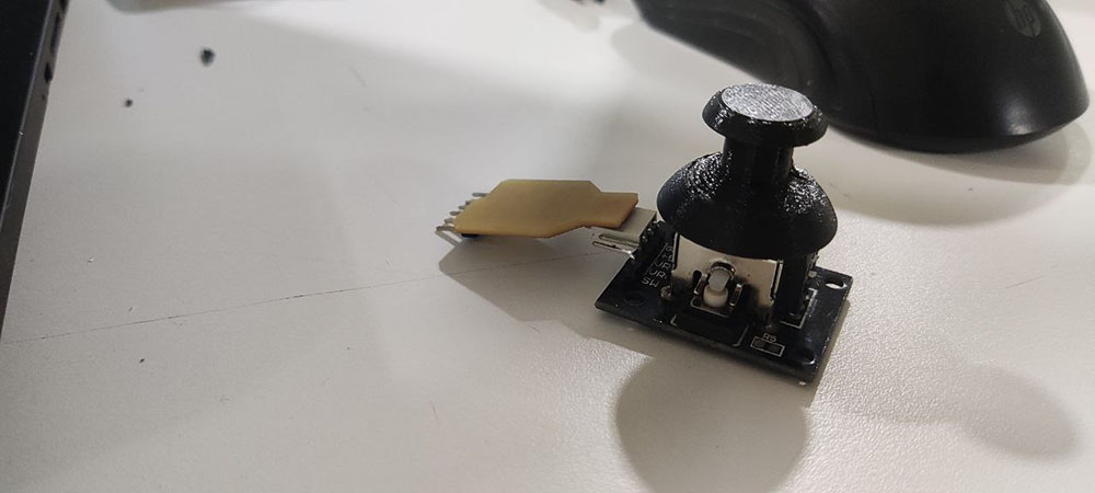
Using this board I ran another code which lights up an LED when the when the joystick is at one position and the LED is set to blink when on the other position and when not doing anything I remains OFF…
//Code for the slave board
#include<Wire.h>
int x;
int led1 = 4;//LED pin

void setup() {
  pinMode (led1, OUTPUT);//Connect LED to pin 4
  Wire.begin(9);//9 here is the address(Mentioned even in the master board code)
  Wire.onReceive(receiveEvent);
  Serial.begin(9600);
}
void receiveEvent(int bytes) {
  x = Wire.read();//Receive value from master board
  Serial.print(x);
}
void loop() {
  if (x > 254) {//I took the threshold as 88,you can change it to whatever you want
    digitalWrite(led1, HIGH);
    }
  else if (x < 210) {
    digitalWrite(led1, HIGH);
    delay(200);
    digitalWrite(led1, LOW);
    delay(200);

    }

  else {
    digitalWrite(led1, LOW);
  }
}
Used the Arduino Uno board just to fine tune the code before using it with the slave baord
Now that both the Master and Slave boards are ready I made a ribon cable that can connect between 2 motor driver boards and the master board
Group Assignment
Using Joshwin’s board we wrote a program to communicate between our projects
//Code for the Master board
#include<Wire.h>//This library is used for I2C communication
int x;
void setup() {
  Wire.begin();
  Serial.begin(115200);
}
void loop() {
  x = Serial.parseInt();//Reading value
  Wire.beginTransmission(9);//9 here is the address of the slave board
  Wire.write(x);//Transfers the value of potentiometer to the slave board
  Wire.endTransmission();
  Serial.print(x);
  delay(1000);
}
//Code for the slave board
#include<Wire.h>
int x;
int led1 = 4;

void setup() {
  pinMode (led1, OUTPUT);//Connect LED to pin 4
  Wire.begin(9);//9 here is the address(Mentioned even in the master board code)
  Wire.onReceive(receiveEvent);
  Serial.begin(9600);
}
void receiveEvent(int bytes) {
  x = Wire.read();//Receive value from master board
  Serial.print(x);
}
void loop() {
  if (x == 1) {//I took the threshold as 88,you can change it to whatever you want
    digitalWrite(led1, HIGH);
  }
  else if (x == 0) {
    digitalWrite(led1, LOW);
  }
}
You can find Joshwin’s code on his page or in the Group Page